US18529A - Machinery for spinning flax and hemp - Google Patents
Machinery for spinning flax and hemp Download PDFInfo
- Publication number
- US18529A US18529A US18529DA US18529A US 18529 A US18529 A US 18529A US 18529D A US18529D A US 18529DA US 18529 A US18529 A US 18529A
- Authority
- US
- United States
- Prior art keywords
- shaft
- bar
- attached
- nippers
- pulley
- Prior art date
- Legal status (The legal status is an assumption and is not a legal conclusion. Google has not performed a legal analysis and makes no representation as to the accuracy of the status listed.)
- Expired - Lifetime
Links
- 238000009987 spinning Methods 0.000 title description 7
- 244000025254 Cannabis sativa Species 0.000 title description 5
- 235000012766 Cannabis sativa ssp. sativa var. sativa Nutrition 0.000 title description 5
- 235000012765 Cannabis sativa ssp. sativa var. spontanea Nutrition 0.000 title description 5
- 235000009120 camo Nutrition 0.000 title description 5
- 235000005607 chanvre indien Nutrition 0.000 title description 5
- 239000011487 hemp Substances 0.000 title description 5
- 241000208202 Linaceae Species 0.000 title description 4
- 235000004431 Linum usitatissimum Nutrition 0.000 title description 4
- 239000000835 fiber Substances 0.000 description 13
- 239000002184 metal Substances 0.000 description 3
- 229910052751 metal Inorganic materials 0.000 description 3
- 230000000630 rising effect Effects 0.000 description 3
- 239000002657 fibrous material Substances 0.000 description 2
- 238000000034 method Methods 0.000 description 2
- 238000005192 partition Methods 0.000 description 2
- 238000005096 rolling process Methods 0.000 description 2
- 238000004804 winding Methods 0.000 description 2
- AXTADRUCVAUCRS-UHFFFAOYSA-N 1-(2-hydroxyethyl)pyrrole-2,5-dione Chemical compound OCCN1C(=O)C=CC1=O AXTADRUCVAUCRS-UHFFFAOYSA-N 0.000 description 1
- 238000010276 construction Methods 0.000 description 1
- 230000000994 depressogenic effect Effects 0.000 description 1
- 230000000694 effects Effects 0.000 description 1
- 238000009984 hand spinning Methods 0.000 description 1
- 239000007937 lozenge Substances 0.000 description 1
- 239000000463 material Substances 0.000 description 1
- 230000001105 regulatory effect Effects 0.000 description 1
Images

Classifications
-
- D—TEXTILES; PAPER
- D01—NATURAL OR MAN-MADE THREADS OR FIBRES; SPINNING
- D01H—SPINNING OR TWISTING
- D01H5/00—Drafting machines or arrangements ; Threading of roving into drafting machine
- D01H5/18—Drafting machines or arrangements without fallers or like pinned bars
- D01H5/26—Drafting machines or arrangements without fallers or like pinned bars in which fibres are controlled by one or more endless aprons
Definitions
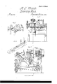
- FIG. 1 is a view of an improved machine for spinning hemp, flax, &c., the apparatus for laying up the spun thread being shown with it as the same drawing motion is applied to both.
- Fig. 2 is a longitudinal vertical section through the same on the line a of Fig. 3.
- Fig. 3 is a transverse vertical section on the line y y of Fig. 2.
- Figs. t and 5 details to be referred to.
- the object of my present invention is to obtain a machine by which I can spin hemp, flax, and similar fibrous material directly from the hanl without the necessity of lirst forming it into a sliver, thus doing away with the drawing rolls and much of the expensive part of the operation of spinning, and substituting therefor a drawing movement that more closely resembles that of hand spinning, and which allows the twist given by the spindle to follow up close to the hank from which the fibers are drawn.
- A. is the frame of the machine on top of which is secured in suitable bearings the shaft B to which power is applied through the pulley C on one end of it.
- a belt a. from another pulley at the other end of the shaft gives motion through a pulley L (Fig. 2) to a shaft D, which carries a long drum E from which belts communicate motion to the spindles F and G. and to other parts of the machine as will be explained.
- a pulley H on the shaft D and belt b gives motion to the pulley I, on the cam shaft K, which has its bearings at the two sides of the frame A, and extends across the machine.
- the belt c over a smaller pulley attached to the inner face of the pulley I gives motion to the pulley M that is carried on a short shaft having its bearing on the top piece of the frame A.
- an eccentric cam N which operates a lever O, pivoted at one end on the shaft P; this shaft is supported in bearings on two of the uprights or legs of the frame A, and extends across from one side to the other of the frame.
- the lever C is held in contact with the cam N by a spring cl, and has pivoted to it near the middle of its length a pawl c, that operates a ratchet wheel Q, secured to the shaft P.
- a retaining pawl f for this wheel is pivoted to the side of the frame A.
- the shaft P carries two heart shaped cams It, (one of which is seen in Fig.
- a box V, for the reception of the hank is formed of a middle partition l to which is hinged on either side two sides or flaps 2 which are supplied with teeth z' (see Fig. l). These side iaps are opened and the hank is laid longitudinally over the partition l, with the bight projecting from the front of the box. The flaps 2, are then closed down over it, and the box is placed in a trough V, into which the box fits. This trough is attached at its rear end by a single screw h5, passing through the bottom of it to a bar W, that extends across the rear end of the machine and is pivoted at each end to the frame A.
- This trough also rests near the middle of its length on a short standard 7c, attached to a bar X, the two ends of which slide up and down in grooves in the inner sides of the frame A.
- This bar rests on the two cams R and as they are revolved the trough V, is
- a bar Y (Figs. 2 and 3) extends across the machine and is allowed to .play longitudinally through slots in the sides of the frame A.
- One end extends through the frame and is held in contact with a cam Z, on the inner face of the pulley M, by a spring m, attached to the rod and to the inside of the frame A.
- a rod n rises from the rod Y up attached to the frame and to the upper part of the block B.
- the bar A is furnished with two pairs of nippers, one pair marked 5, near one end of the spinning apparatus and one pair marked 6 near the other end for the laying up apparatus. They are formed of a stationary jaw t, fixed firmly to the bar, and a movable jaw u pivoted to the bar, the movable jaws of each pair being connected together by a rod o so that the vibration of one shall move the other.
- a block a on one of these movable jaws is held in contact with the side of the cam 3, by a spring w attached to the other aw u and to the side of the frame.
- the cam 3 is cut away on its side to the proper form (as seen dotted in Fig.
- a similar pair marked 7 is attached to the bar B for the laying up apparatus, and a pair of draw nippers of a different construction marked 8 are attached to the other end of this bar for the spinning apparatus.
- This latter pair is j formed of two bent arms c d (Figs. 1 and 5,) pivoted together at e3, to the back of the bar B.
- the arm d is furnished with a sheet metal jaw e which shuts into a double sheet metal jaw f attached to the arm c.
- each of these jaws is notched, forming when they are together a loZenge shaped hole which is enlarged and contracted by the vibration of the arms c, d; this vibration is effected by the shaft K, in the following manner:
- a lever E is pivoted at g to the back of the bar B.
- a small block h attached to the lower end of this lever is held in contact with the side of a cam g, on the shaft K, by a spring L* attached to the upper end of this lever and to the bar B.
- a flat rod z" connects the upper end of the lever E, to the lower branch of the arm c and a flat rod c, with a slot at Z connects the other end of the same lever to the lower branch of the arm d.
- a spring m is attached to the rod 7c and to the lever E. This method of connecting the lever E, to the arm d allows the bite of the jaws e-f to accommodate itself to the varying quantity of fiber drawn through them.
- a rod n is attached to the arm c and to the movable jaw of nipper 7 which is thus vibrated with the arm c.
- the blocks A, B are vibrated toward and from each lother and the two pairs of nippers attached to one bar are opened and shut in alternation with the two pairs on the other bar.
- a stout 'bar F extends across the machine and is pivoted at 0 to the inner side of the frame A.
- an arm Gr' which is formed in two parts hinged together at r, near the middle of its length.
- the other end of this arm is attached to a bar H (Fig. 3) which is pivoted at one end to the frame A and at the other to a standard I rising from the middle cross brace of the frame.
- the arm G is held by a spring K in contact with a cam l0, on the shaft K, by the revolution of which the elbow at r is depressed and the two bars F, and H, are Vibrated.
- rise two standards p which carry at their upper ends a shaft 1 7 having secured to its outer end beyond one of the standards a pulley s to which is attached a cord t, which passes over the pulley and is attached at its other end to the part 3 of a treadle L seen enlarged in Fig. t, which is attached to the bar F.
- This treadle is formed of three parts, No. 1 being rigid, and vibrating with the bar F. No. 3, is pivoted at u to No.
- the shaft g carries a metallic disk z with a single hooked notch or tooth in its periphery, which whenever this shaft is revolved by the cord t is thrown up into contact with the fibers being drawn from the hank, and as the block H is vibrated as before explained, the hook in the disk z draws out more of the fibers from the hank and increases the quantity being drawn out by the draw nippers 8. That this may only occur when the nippers 8 are not drawing out sufliciently fast, the following device is used for regulating this part of the operation: A lever a2 is pivoted to the top of the arm CZ of the nippers 8.
- the spools l, 2, 3, containing the spun yarn are secured to the heads A2, B2, C2, which are carried on a standard D2 rising from the end of the frame A and are revolved all in one direction by a band Z2 leading over the drum E.
- the ends of these yarns are lead through a hole in a metal plate or guide @2 (Figs. 2 and 3) which keeps them in contact with each other, thence between two metalic disks f2--z2, thence between the draw nippers 7 and 6, thence over a guide pulley O on the shaft B, to the spindle G, where the laid up cord or rope is wound up on a spool on this spindle.
- ' nippers 7 and 6 are opened and shut and vibrated to and from each other by the revolution of the shaft K, as before explained.
- the disks f2, z2 are carried' on the ends of two short shafts h2 2 which are supported on standards Z2 rising from a block P which is attached at one end to the side of the frame A and is supported at the other end by the upright I.
- These shafts h2, 2 are revolved in opposite directions by bands leading over pulleys on these shafts and over a drum Q which is driven by a band m2 leading over the drum E.
- the shaft h2 is allowed to play longitudinally in its bearings in the standards Z2 and the disk f2 is pressed toward the disk .e2 by a spring n2 secured to one of the standards Z2.
- these disks accommodate themselves to any variation in the thickness of the cord or rope being laid up at the same time that their surfaces revolving in opposite directions in contact with the cord as the twist is laid in, compensates in a measure for the difference of thickness of the yarns or strands and prevents the larger strand from winding around the smaller ones, as it is apt to do when laid up in the customary manner.
- each of these pulleys is furnished with one or more inclined wires or staples 3 which are secured in the groove of the pulley and lie diagonally across it.
- these inclined staples or teeth act upon the twist and pass it over the pulley, and the pulley does not stop the twist as it would do if the staples 3 were not placed in the groove.
- a diagonal notch or groove may be cut across the groove of the pulley. This will have a similar effect in passing the twist over the pulley.
- the spun yarn thus formed is taken from the spindle F to the laying up apparatus, the spools being attached to the revolving heads A2, B2, G2, from which the threads are led through the guide e2, between the disks f2 z2, through the nippers 7 and 6, over the guide pulley O to the spindle Gr, by which the twist is laid in and the finished cord or rope is wound up.
- the draw nippers 7 and 6 are opened alternately and allow the twist of the cord to run up to the guide e2 of the disks f2 g2, rolling in the twist as before explained and compelling the various strands to place themselves in a uniform position around the central axis of the cord or rope, which will enable me to produce a smoother and stronger article than has heretofore been possible where the strands were allowed to adjust themselves around the axis of the article being laid up, when a variation in the thickness of either strand would cause an irregularity in the twist and consequently in the strain brought upon the different strands when traction was applied longitudinally to the rope.
Landscapes
- Engineering & Computer Science (AREA)
- Mechanical Engineering (AREA)
- Textile Engineering (AREA)
- Spinning Or Twisting Of Yarns (AREA)
Description
UNITED STATES PATENT OFFICE.,
MILTON D. WI-IIPPLE, 0F CHARLESTOIVN, MASSACHUSETTS, ASSIGNOR TO ALFRED B. ELY,
OF NEIVTON, MASSACHUSETTS.
MACHINERY FOR SPINNING FLAX ANDy HEMI?.
Specicaton of Letters Patent No. 18,529, dated October 27, 1857.
To all 'whom it may concer/n:
Be it known that I, MILTON D. IVHIPPLE, of Charlestown, in the county of Middlesex and State of Massachusetts, have invented certain new and useful Improvements in Machinery for Spinning and for Laying Up Hemp and Similar F ibrous Material; and I hereby declare the following to be a full, clear, and exact description of the same, reference being had to the accompanying drawings, making part of this specification, in which- Figure 1 is a view of an improved machine for spinning hemp, flax, &c., the apparatus for laying up the spun thread being shown with it as the same drawing motion is applied to both. Fig. 2 is a longitudinal vertical section through the same on the line a of Fig. 3. Fig. 3 is a transverse vertical section on the line y y of Fig. 2. Figs. t and 5 details to be referred to.
The object of my present invention is to obtain a machine by which I can spin hemp, flax, and similar fibrous material directly from the hanl without the necessity of lirst forming it into a sliver, thus doing away with the drawing rolls and much of the expensive part of the operation of spinning, and substituting therefor a drawing movement that more closely resembles that of hand spinning, and which allows the twist given by the spindle to follow up close to the hank from which the fibers are drawn. As this same drawing principle is applicable to laying up the spun thread or forming rope I have shown the manner in which it may be applied to such purpose, as well as an improved method of laying up such strands by rolling them together between two disks as the twist is laid in and thus compensating for any difference in the thickness of the strands.
In the drawings A. is the frame of the machine on top of which is secured in suitable bearings the shaft B to which power is applied through the pulley C on one end of it. A belt a. from another pulley at the other end of the shaft gives motion through a pulley L (Fig. 2) to a shaft D, which carries a long drum E from which belts communicate motion to the spindles F and G. and to other parts of the machine as will be explained. A pulley H on the shaft D and belt b gives motion to the pulley I, on the cam shaft K, which has its bearings at the two sides of the frame A, and extends across the machine. The belt c over a smaller pulley attached to the inner face of the pulley I gives motion to the pulley M that is carried on a short shaft having its bearing on the top piece of the frame A.
Attached to the outer face of the pulley M, is an eccentric cam N, which operates a lever O, pivoted at one end on the shaft P; this shaft is supported in bearings on two of the uprights or legs of the frame A, and extends across from one side to the other of the frame. The lever C is held in contact with the cam N by a spring cl, and has pivoted to it near the middle of its length a pawl c, that operates a ratchet wheel Q, secured to the shaft P. A retaining pawl f for this wheel is pivoted to the side of the frame A. The shaft P carries two heart shaped cams It, (one of which is seen in Fig. 2.) These cams operate two levers S, pivoted at g, to the inside of the longitudinal ties of the frame A. Through these levers is operated a gate T, sliding up and down in the frame A. Stirrups L, attached to the gate T, embrace the spindles F and G, and as the levers S, are vibrated the spools on these spindles are raised and lowered to regulate the winding on. The cams It perform another office which will now be explained.
A box V, for the reception of the hank is formed of a middle partition l to which is hinged on either side two sides or flaps 2 which are supplied with teeth z' (see Fig. l). These side iaps are opened and the hank is laid longitudinally over the partition l, with the bight projecting from the front of the box. The flaps 2, are then closed down over it, and the box is placed in a trough V, into which the box fits. This trough is attached at its rear end by a single screw h5, passing through the bottom of it to a bar W, that extends across the rear end of the machine and is pivoted at each end to the frame A. This trough also rests near the middle of its length on a short standard 7c, attached to a bar X, the two ends of which slide up and down in grooves in the inner sides of the frame A. This bar rests on the two cams R and as they are revolved the trough V, is
vibrated vertically a short distance, the bar 7, swinging on its pivots; the trough Vnis also caused to vibrate horizontally on its pivot h5 in the following manner. A bar Y, (Figs. 2 and 3) extends across the machine and is allowed to .play longitudinally through slots in the sides of the frame A. One end extends through the frame and is held in contact with a cam Z, on the inner face of the pulley M, by a spring m, attached to the rod and to the inside of the frame A. A rod n rises from the rod Y up attached to the frame and to the upper part of the block B. These cams are so arranged that as the shaft K, revolves, the bars A, B alternately approach to and recede from each other.
The bar A is furnished with two pairs of nippers, one pair marked 5, near one end of the spinning apparatus and one pair marked 6 near the other end for the laying up apparatus. They are formed of a stationary jaw t, fixed firmly to the bar, and a movable jaw u pivoted to the bar, the movable jaws of each pair being connected together by a rod o so that the vibration of one shall move the other. A block a on one of these movable jaws is held in contact with the side of the cam 3, by a spring w attached to the other aw u and to the side of the frame. The cam 3 is cut away on its side to the proper form (as seen dotted in Fig. Thus these nippers are opened and shut by the revolution of the shaft K. A similar pair marked 7 is attached to the bar B for the laying up apparatus, and a pair of draw nippers of a different construction marked 8 are attached to the other end of this bar for the spinning apparatus. This latter pair is j formed of two bent arms c d (Figs. 1 and 5,) pivoted together at e3, to the back of the bar B. The arm d is furnished with a sheet metal jaw e which shuts into a double sheet metal jaw f attached to the arm c. The edge of each of these jaws is notched, forming when they are together a loZenge shaped hole which is enlarged and contracted by the vibration of the arms c, d; this vibration is effected by the shaft K, in the following manner: A lever E is pivoted at g to the back of the bar B. A small block h attached to the lower end of this lever is held in contact with the side of a cam g, on the shaft K, by a spring L* attached to the upper end of this lever and to the bar B. A flat rod z" connects the upper end of the lever E, to the lower branch of the arm c and a flat rod c, with a slot at Z connects the other end of the same lever to the lower branch of the arm d. A spring m is attached to the rod 7c and to the lever E. This method of connecting the lever E, to the arm d allows the bite of the jaws e-f to accommodate itself to the varying quantity of fiber drawn through them. A rod n is attached to the arm c and to the movable jaw of nipper 7 which is thus vibrated with the arm c. Thus as the shaft K is revolved the blocks A, B, are vibrated toward and from each lother and the two pairs of nippers attached to one bar are opened and shut in alternation with the two pairs on the other bar.
To insure the drawing out from the hank of a sufficient quantity of fiber to make the yarn being spun uniform, I have adopted the following device: A stout 'bar F, extends across the machine and is pivoted at 0 to the inner side of the frame A. To this bar at one end is attached an arm Gr', which is formed in two parts hinged together at r, near the middle of its length. The other end of this arm is attached to a bar H (Fig. 3) which is pivoted at one end to the frame A and at the other to a standard I rising from the middle cross brace of the frame. The arm G is held by a spring K in contact with a cam l0, on the shaft K, by the revolution of which the elbow at r is depressed and the two bars F, and H, are Vibrated. From the bar H', rise two standards p which carry at their upper ends a shaft 1 7 having secured to its outer end beyond one of the standards a pulley s to which is attached a cord t, which passes over the pulley and is attached at its other end to the part 3 of a treadle L seen enlarged in Fig. t, which is attached to the bar F. This treadle is formed of three parts, No. 1 being rigid, and vibrating with the bar F. No. 3, is pivoted at u to No. l, and has attached at its outer end the cord t. No. 2, lies between l, and 3 and is pivoted to No. l, and when in the position shown in the drawings wedges them apart so that the outer end of No. 3 will not be caught by the projecting lip v, of a block w attached to the outer end of No. l, but when No. 2, is raised by a rod m in a manner which will be explained the parts No. l, and No. 3 spring together and No. 3, is caught under the block fw and it is vibrated with No. l, by the bar F thus drawing down the cord 25 and causing the shaft g to revolve a portion of a circle in the direction of the arrow Fig. 2. An elastic belt y (Fig. 3,) attached to the shaft and to the bar H', turns the shaft back again when the cord t, is slacked up.
The shaft g carries a metallic disk z with a single hooked notch or tooth in its periphery, which whenever this shaft is revolved by the cord t is thrown up into contact with the fibers being drawn from the hank, and as the block H is vibrated as before explained, the hook in the disk z draws out more of the fibers from the hank and increases the quantity being drawn out by the draw nippers 8. That this may only occur when the nippers 8 are not drawing out sufliciently fast, the following device is used for regulating this part of the operation: A lever a2 is pivoted to the top of the arm CZ of the nippers 8. To the outer end of this lever is pivoted the rod the other end of'which is pivoted to the part 2 of the treadle L. To the top of the arm c of these nippers is attached a set screw b2 the end of which projects a short distance toward the arm (Z. The lever a2 is allowed to vibrate freely and the part N o. 2 is carried with the treadle L, but whenever the amount of fiber passing through between the jaws f and e of the nippers 8 becomes reduced below what is required, it allows the jaws to come closer together and the short end of the lever a2 is caught under the end of the screw b2 and the lever is prevented from vibrating, and the wedge No. 2 of the treadle L is held up by the rod w and the parts llo. l and No. 3 are allowed to spring together, when No. 3 is caught under the block w and is vibrated with the part No.1 by the bar F. This draws down the cord t and revolves the shaft g as before explained and the hook on the disk e is thrown up among the fibers and this motion of the disk in connection with the vibration of the bar H draws out some more of the fibers from the hank and increases the quantity grasped between the jaws of the nippers S, which prevents them from coming so close together as to let the end of the lever a2 catch under the set screw b2 when the wedge No. 2 of the treadle L drops into the position shown in Fig. 4, and the part No. 3 is held off so that it does not catch under the block w and the treadle L vibrates without drawing down the part No. 3, which is left free to vibrate on its pivot u. The shaft Q is now revolved a part of a turn in the opposite direction by the retraction of the elastic band y and the hook of the disk e is thrown down (as in Fig. 2) out of the way of the fibers and although the bar H continues to be vibrated as before the fibers are only drawn out by the action of the nippers 8.
The laying` up part of my improved machine will now be described.
The spools l, 2, 3, containing the spun yarn are secured to the heads A2, B2, C2, which are carried on a standard D2 rising from the end of the frame A and are revolved all in one direction by a band Z2 leading over the drum E. The ends of these yarns are lead through a hole in a metal plate or guide @2 (Figs. 2 and 3) which keeps them in contact with each other, thence between two metalic disks f2--z2, thence between the draw nippers 7 and 6, thence over a guide pulley O on the shaft B, to the spindle G, where the laid up cord or rope is wound up on a spool on this spindle. The
' nippers 7 and 6 are opened and shut and vibrated to and from each other by the revolution of the shaft K, as before explained. The disks f2, z2, are carried' on the ends of two short shafts h2 2 which are supported on standards Z2 rising from a block P which is attached at one end to the side of the frame A and is supported at the other end by the upright I. These shafts h2, 2, are revolved in opposite directions by bands leading over pulleys on these shafts and over a drum Q which is driven by a band m2 leading over the drum E. The shaft h2 is allowed to play longitudinally in its bearings in the standards Z2 and the disk f2 is pressed toward the disk .e2 by a spring n2 secured to one of the standards Z2. Thus these disks accommodate themselves to any variation in the thickness of the cord or rope being laid up at the same time that their surfaces revolving in opposite directions in contact with the cord as the twist is laid in, compensates in a measure for the difference of thickness of the yarns or strands and prevents the larger strand from winding around the smaller ones, as it is apt to do when laid up in the customary manner.
That the twist given to the yarn or cord by the spindles F and G may pass over the guide pulleys R, O, on the shaft B, and run up toward the nippers, each of these pulleys is furnished with one or more inclined wires or staples 3 which are secured in the groove of the pulley and lie diagonally across it. As the pulley revolves, these inclined staples or teeth act upon the twist and pass it over the pulley, and the pulley does not stop the twist as it would do if the staples 3 were not placed in the groove. Instead of these staples a diagonal notch or groove may be cut across the groove of the pulley. This will have a similar effect in passing the twist over the pulley.
Operation: The hank of hemp, flax, or other fibrous material to be spun, is placed in the box U, as before described, and the fibers are drawn from the bight or middle of it over the disk z through between the jaws of the nippers 8, then through between the jaws of the nippers 5, thence over the guide pulley R on the shaft B, to the spindle F, which is revolved as before explained. By this spindle the twist is given to the thread, and by the vibration of the blocks A B and the opening and closing of the nippers 5 and 8 the bers are drawn out from the hank and the twist is allowed to run up close to the hank, as it could not do if draw rolls were used instead of these draw nippers. l thus avoid the necessity of forming the fibers into a sliver by means of extra machinery before it is spun. The operation of the hook on the disk e as explained keeps the amount of fibers drawn out by the nippers 8, uniform. The spun yarn thus formed is taken from the spindle F to the laying up apparatus, the spools being attached to the revolving heads A2, B2, G2, from which the threads are led through the guide e2, between the disks f2 z2, through the nippers 7 and 6, over the guide pulley O to the spindle Gr, by which the twist is laid in and the finished cord or rope is wound up. The draw nippers 7 and 6 are opened alternately and allow the twist of the cord to run up to the guide e2 of the disks f2 g2, rolling in the twist as before explained and compelling the various strands to place themselves in a uniform position around the central axis of the cord or rope, which will enable me to produce a smoother and stronger article than has heretofore been possible where the strands were allowed to adjust themselves around the axis of the article being laid up, when a variation in the thickness of either strand would cause an irregularity in the twist and consequently in the strain brought upon the different strands when traction was applied longitudinally to the rope.
forth whereby the twist is allowed to run up.
3. claim the vibrating hank holder U constructed and operating substantially as described.
4. I claim the inclined wires or teeth on the guide pulley O R operating in the manner and for the purpose substantially as set forth.
MILTON D. l/VHIPPLE.
Witnesses:
THos. R. RoAoH, P. E. TESOHEMACHER.
Publications (1)
| Publication Number | Publication Date |
|---|---|
| US18529A true US18529A (en) | 1857-10-27 |
Family
ID=2081923
Family Applications (1)
| Application Number | Title | Priority Date | Filing Date |
|---|---|---|---|
| US18529D Expired - Lifetime US18529A (en) | Machinery for spinning flax and hemp |
Country Status (1)
| Country | Link |
|---|---|
| US (1) | US18529A (en) |
-
0
- US US18529D patent/US18529A/en not_active Expired - Lifetime
Similar Documents
| Publication | Publication Date | Title |
|---|---|---|
| US18529A (en) | Machinery for spinning flax and hemp | |
| US689556A (en) | Machinery for spinning and twisting fibrous materials. | |
| US21932A (en) | Machinery for combing cotton | |
| US6942A (en) | Improvement in machinery for making cord | |
| US14938A (en) | Improvement in machinery for making rope and cordage | |
| US37584A (en) | Improvement in machinery for coating thread of one fiber with another fiber | |
| US16694A (en) | Improvement in cordage-machines | |
| US69211A (en) | hadley | |
| US16365A (en) | Improvement in hemp-brakes | |
| US7701A (en) | Machinery fob | |
| US6441A (en) | Improvement in machinery for laying ropes | |
| US15623A (en) | Machinery eor filling seine-needles | |
| US6388A (en) | Machinery eos | |
| US99055A (en) | Improvement in spinning-machines | |
| US573676A (en) | Spinning-machine | |
| US421824A (en) | Btjry | |
| US321924A (en) | Joseph e | |
| US948320A (en) | Yarn-winding machine. | |
| US4638A (en) | Spinning- hemp | |
| US763378A (en) | Machinery for manufacturing yarn from fibrous materials. | |
| US16867A (en) | Improvement in cordage-machines | |
| USRE423E (en) | Improvement in machinery for making cord | |
| US21164A (en) | Thomas b | |
| US125688A (en) | Improvement in machines for doubling and twisting yarns | |
| US689787A (en) | Machine for twisting cotton slivers. |