US1852990A - Safety door holder - Google Patents
Safety door holder Download PDFInfo
- Publication number
- US1852990A US1852990A US546553A US54655331A US1852990A US 1852990 A US1852990 A US 1852990A US 546553 A US546553 A US 546553A US 54655331 A US54655331 A US 54655331A US 1852990 A US1852990 A US 1852990A
- Authority
- US
- United States
- Prior art keywords
- door
- pawl
- plate
- ratchet wheel
- safety door
- Prior art date
- Legal status (The legal status is an assumption and is not a legal conclusion. Google has not performed a legal analysis and makes no representation as to the accuracy of the status listed.)
- Expired - Lifetime
Links
- 241001214257 Mene Species 0.000 description 1
- 101150057833 THEG gene Proteins 0.000 description 1
- 238000005452 bending Methods 0.000 description 1
Images

Classifications
-
- E—FIXED CONSTRUCTIONS
- E05—LOCKS; KEYS; WINDOW OR DOOR FITTINGS; SAFES
- E05C—BOLTS OR FASTENING DEVICES FOR WINGS, SPECIALLY FOR DOORS OR WINDOWS
- E05C17/00—Devices for holding wings open; Devices for limiting opening of wings or for holding wings open by a movable member extending between frame and wing; Braking devices, stops or buffers, combined therewith
- E05C17/02—Devices for holding wings open; Devices for limiting opening of wings or for holding wings open by a movable member extending between frame and wing; Braking devices, stops or buffers, combined therewith by mechanical means
- E05C17/04—Devices for holding wings open; Devices for limiting opening of wings or for holding wings open by a movable member extending between frame and wing; Braking devices, stops or buffers, combined therewith by mechanical means with a movable bar or equivalent member extending between frame and wing
- E05C17/32—Devices for holding wings open; Devices for limiting opening of wings or for holding wings open by a movable member extending between frame and wing; Braking devices, stops or buffers, combined therewith by mechanical means with a movable bar or equivalent member extending between frame and wing consisting of two or more pivoted rods
- E05C17/34—Devices for holding wings open; Devices for limiting opening of wings or for holding wings open by a movable member extending between frame and wing; Braking devices, stops or buffers, combined therewith by mechanical means with a movable bar or equivalent member extending between frame and wing consisting of two or more pivoted rods with means for holding in more than one position
-
- Y—GENERAL TAGGING OF NEW TECHNOLOGICAL DEVELOPMENTS; GENERAL TAGGING OF CROSS-SECTIONAL TECHNOLOGIES SPANNING OVER SEVERAL SECTIONS OF THE IPC; TECHNICAL SUBJECTS COVERED BY FORMER USPC CROSS-REFERENCE ART COLLECTIONS [XRACs] AND DIGESTS
- Y10—TECHNICAL SUBJECTS COVERED BY FORMER USPC
- Y10S—TECHNICAL SUBJECTS COVERED BY FORMER USPC CROSS-REFERENCE ART COLLECTIONS [XRACs] AND DIGESTS
- Y10S292/00—Closure fasteners
- Y10S292/12—Closure operators
-
- Y—GENERAL TAGGING OF NEW TECHNOLOGICAL DEVELOPMENTS; GENERAL TAGGING OF CROSS-SECTIONAL TECHNOLOGIES SPANNING OVER SEVERAL SECTIONS OF THE IPC; TECHNICAL SUBJECTS COVERED BY FORMER USPC CROSS-REFERENCE ART COLLECTIONS [XRACs] AND DIGESTS
- Y10—TECHNICAL SUBJECTS COVERED BY FORMER USPC
- Y10T—TECHNICAL SUBJECTS COVERED BY FORMER US CLASSIFICATION
- Y10T292/00—Closure fasteners
- Y10T292/28—Extension link
- Y10T292/282—Multiple
-
- Y—GENERAL TAGGING OF NEW TECHNOLOGICAL DEVELOPMENTS; GENERAL TAGGING OF CROSS-SECTIONAL TECHNOLOGIES SPANNING OVER SEVERAL SECTIONS OF THE IPC; TECHNICAL SUBJECTS COVERED BY FORMER USPC CROSS-REFERENCE ART COLLECTIONS [XRACs] AND DIGESTS
- Y10—TECHNICAL SUBJECTS COVERED BY FORMER USPC
- Y10T—TECHNICAL SUBJECTS COVERED BY FORMER US CLASSIFICATION
- Y10T292/00—Closure fasteners
- Y10T292/306—Gear
- Y10T292/308—Swinging catch
Definitions
- a Ain object ofthe invention istorprovide a device'offthe character Stated which is @otsimple-1 anddnrable struetureandlwhich when applied tothe door will w'holdftheisame- Secure- *at an openedf'or closedlposition 'and pre 7m vent the-do or from'f accidentallyVA closing and also prevent-the same frombeing openedlexgceptldy one-whoisat-the inside ofthel garage building.
- AE yp'awl is pivotally mounted 'Lnpon @the plate andis provided 'with' a spur adaptedto en'gfglgebetweenA the teethA off ⁇ the ratchet 20 wheel?
- the iirst mene ti-onedplate; is .provided witl1--v ast'oplug 1ocatedtiithepath'oif'movement of the pawl and adapted to limit the swinging movement thereof in a direction away from the center o the ratchet wheel.
- An arm is fixed to Jthe ratchet wheelr and is pivotally connected at its inner end with the end of a link which in turn is pivotally connected at one end with the frame of the door ypreferably at a point Aapproximately midway between the sides of a door opening inthe wall of the building. 1215
- the arm is provided withy a lug adapted to limit the swinging movement of the lilik.
- Figure 1 is a top plan view of a door showing the same at opened position and with the s'50 safety holder applied.
- lligurar 3 iseal side elevational Afv'evm'ofathe upperj portion 1 off the door ⁇ - ⁇ with f the; holder applied: f g5 f,
- e de() Fignref isiy a;l detailed .i perspective lviewzfof the fa dj acentfendslogthev. arm .and flink; f
- Eigure 7 is an enlargedplan--view ofv both plates usedteinthe devices.
- a plate 15 is mounted upon the frame of the door above the door opening and a downwardly extending lug 16 is adj ustahly mounted upon the plate 15 and is disposed in the path of movement of the hook 6 of the pawl.
- the spring moves the pawl so that the spur thereof engages in the teeth of the ratchet wheel and the hook thereof engages the lug 16.
- This device will have a tendency to eliminate danger of the door swinging and breaking or bending a car fender. It will hold the door open without any special operation regardless of snow, ice or conditions of the driveway. It will hold the door closed so that it may not be opened exceptfrom the inside of the garage. It may be used on any hinged door, it is strong and durable and inexpensive. By reversing the ratchet and pawl this device may be used to advantage upon other swinging objects as for instance gates.
- a door holder comprising a plate for at tachment to the door, a ratchet wheel journaled upon the plate, a pawl pivoted upon the plate and having a spur adapted to enter between the teeth of the ratchet wheel, a spring for holding the pawl toward the ratchet wheel, means for moving the pawl away from the ratchet wheel, an arm fixed t0 the ratchet wheel, and a link pivoted to the arm and adapted to be pivotally connected with the frame of the door.
- a door holder comprising a plate adapted to be attached to the door, a ratchet wheel journaled upon the plate, a pawl pivoted upon the plate and having a spur adapted to enter the spaces between the teeth of the ratchet wheel, a spring for holding the pawl toward the ratchet wheel, a stop member mounted upon the plate and located at the side of the free end ot the pawl, a pull member connected with the pawl and extending in the direction of said stop member, an arm iixed to the ratchet wheel and a link pivotally connected with the arm and adapted to be pivotally connected with the frame of the door.
- a door holder comprising a plate adapted to be attached to the door, a ratchet wheel journaled upon the plate, a pawl pivoted upon the plate and having a. spur adapted to enter the spaces between the teeth of the ratchet wheel, a spring connected with the pawl and the plate and adapted to hold the pawl toward the center of the ratchet wheel, the plate having a stop member located in the path of movement of the free end of the pawl, a fiexible element connected with the pawl and extending in the direction 0f said stop member, an arm fixed at one end to the ratchet wheel and provided at its other end with a stop member and a link pivotally connected at one end with the arm in the vicinity of the last mentioned stop member and adapted to be pivotally connected at its other end with the frame of the door.
Landscapes
- Engineering & Computer Science (AREA)
- Mechanical Engineering (AREA)
- Wing Frames And Configurations (AREA)
Description
I Aprila 1932.
SAFETY DOOR HOLDER Filed June 24, 1951 3 SheeLs-Sheetl l INVENTOR md @lf ATTORNEY April 5 l932 F. F. WANDTKE 1,852,990
` SAFETY DOOR HOLDER Filed June 24, 1951 3 Sheets-SheerI 2 i l l lu md ATroRNEv April 5 1932.. F, WANDTKE 1,852,990
SAFETY DOOR HOLDER Patented.` Apr.y 5, 1932 tss-zeau ERANK;WANDTKEzOI'iWET:DULMTEaMINNESQTAt Y This *inventien-irelates-v lto door holdersffespeeially adapted tobe used-upon garagesand itconsitein the `novel features hereinafter describediandclaimed:
A5 A Ain object ofthe inventionistorprovide a device'offthe character Stated which is @otsimple-1 anddnrable struetureandlwhich when applied tothe door will w'holdftheisame- Secure- *at an openedf'or closedlposition 'and pre 7m vent the-do or from'f accidentallyVA closing and also prevent-the same frombeing openedlexgceptldy one-whoisat-the inside ofthel garage building. Y f
' l e doorholder-consistsofia plate adapted 35 v`toliei appliedto-thelinner-surface of the door and having a-ratchet-1wheel journaled thereon. AE yp'awl is pivotally mounted 'Lnpon @the plate andis provided 'with' a spur adaptedto en'gfglgebetweenA the teethA off` the ratchet 20 wheel? A` springie connected` at one end with the 'free endothe pafwlA and at itsjothjer end "with the plateand afI pull yfmemlo'er leconnectedl with the `:tree end?? o-i the; pawl and trained `arounda pulley, j onrnaled at the-inner 325 l'sideo the-door.; fTliepawl is provided atiits free Aendwith a hook andafpl'a-te `ha.viI 1g--a li'g'adaptedto loevr applied-tothe frame off-the door'so thatfthfe ln'gzwillproj ect lntoethefk path omovement of the Khooked*endpoitlierpawl "1530'andlconseqnently when the doorjisiY closedthe lioolediendwill y.engage the said lugand"Y hold the door. in aclosedfpositionf. i The iirst mene ti-onedplate; is .provided witl1--v ast'oplug 1ocatedtiithepath'oif'movement of the pawl and adapted to limit the swinging movement thereof in a direction away from the center o the ratchet wheel. An arm is fixed to Jthe ratchet wheelr and is pivotally connected at its inner end with the end of a link which in turn is pivotally connected at one end with the frame of the door ypreferably at a point Aapproximately midway between the sides of a door opening inthe wall of the building. 1215 The arm is provided withy a lug adapted to limit the swinging movement of the lilik.
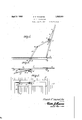
In the accompanying drawings Figure 1 is a top plan view of a door showing the same at opened position and with the s'50 safety holder applied.
Applicationmea :linear 1931-. seriaiflm., 546,553. p
Eigrurelisasimilar-.viewshowing'thedoor at-lclosedposition.; i f
lligurar 3 iseal side elevational Afv'evm'ofathe upperj portion 1 off the door`- `with f the; holder applied: f g5 f,
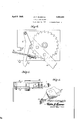
Ei'gure @teisiran enlarged `plan' View. of fthe plate l which gis; applied? to.. the r door and the parts-mounted thereon:v
Fignre51-isan edge elevationalviemofgthe saidplate. e de() Fignref isiy a;l detailed .i perspective lviewzfof the fa dj acentfendslogthev. arm .and flink; f
Eigure 7 is an enlargedplan--view ofv both plates usedteinthe devices.
' Fig-ure 8:is edge elevationalt viewrzzof as the 'fplfateseasshown5in@Y Figure, 7:
Astillustrated" in thegaceompan-ying idram ingsthe doorlofftheegarage isindicatedat; l andifthe rameoithe dor.at=2.I Arfportionfof 4 the :walLofpthe'glarage bnildingsindicated :(0 at! 3.. plate 4Lissappliedrtothesinneresure f taceioff theffdoorf lf; and a; ratchet:wheeli''iis journaledaipon'fsaid plate. t Aapawvlf'iispiv-k oted' upon the plate and-fis-provided f with:A a 1 n spur :72' adaptedY toz enter' the cSpaces'. between '315 f theteeth offtheiratchet wheelfinea` manner asebest shown iniEfiguref et; off'theg; drawings. The ip alwl" 6 is-.pr.ovidedv atrit'ss free end with alhooki Af-.coiled'ispningaf issattacliedf;at' onel end toithe:z plate-4vandconnectedat its 80` other.. endi ,with the; free lfendof1 the :pawl-` 6i The rplate;y 4"- isprovi ded-Lf with -an upstanding lugf 8 which4 `islcatedil in. the; path iv ofcmovementiofthereefendrportion of. thepawl 6': and adaptedi;tofglimit;r the: swinging-a movement.y of 85 the .paw-1 in a direction lawayffrom thecenter of the ratchet wheel 5. A c haineorotherfiiex-l ihle element's-Qfieconnectedl with the free end o1the,paw l;j-G-andtlie ntermediatefportion of a. thechain 9"'is trained over `a pnlley'lO-"which 90 is J'QumeleiatthwpperSeite@ of, the. 1991' 1;@ The. handle; end- 11; Qf'tlechenlhange nendiantfem. there ey 19 asbesthewe in Egureiithe dr'aivizgsa Aeemliead '05 to .fh'era-tchetwheel. Seas show-nxiiifFgurei- One --entl,Q ;the-=.1ink. leapimtallyfcenneted with, than@ 124m-@120mbLadiaeentfthelug otally-connected with the door frame Zapf/efr y:T00 kIl erably at a point approximately midway between the vertical sides thereof.
A plate 15 is mounted upon the frame of the door above the door opening and a downwardly extending lug 16 is adj ustahly mounted upon the plate 15 and is disposed in the path of movement of the hook 6 of the pawl. When the door is in a closed position in the door opening the spring moves the pawl so that the spur thereof engages in the teeth of the ratchet wheel and the hook thereof engages the lug 16.
Assuming that the parts are in the position as shown in Figure 3 of the drawings and it is desired to open the door. A downward pull is exerted upon the handle end 11 at the same time the pawl 6 is swung so that the spur thereof disengages the teeth of the ratchet wheel and the hook 6 disengages the lug 16. Thus the door is unlocked and the door panel 1 may then be swung from a closed position as shown in Figure 3 to an open position as shown in Figure 1 and will remain at such open position for the reason that when the pull is released from the chain 9 the spring 7 returns the pawl to the ratchet wheel.
Assuming that the door is at an open position as shown in Figure 1 of the drawings and it is desired to close the same a downward pull is exerted upon the handle end 11 of the chain 9 whereby the said chain is moved longitudinally and the spur of the pawl 7 is swung out of engagement with the teeth of the ratchet wheel 5. Thus the door may be swung from an open position to a closed position as shown in Figure 2 and when the chain 9 is released the tension of the spring 7 comes into play whereby the spur of the pawl 6 enters between the teeth of the ratchet wheel 5 and the door is secured at a closed position. At the same time the hook will engage the lug 16 and thus the door is locked at a closed position. Vhen the door is moved t-o the opened position as shown in Figure 1 of the drawings the lug 13 upon the arm 12 engages against. the edge of the link 14 and consequently the outward swinging movement of the door with relation to the door frame is limited and the door is rigidly held at an open position when the parts are moved to the position as shown in Figure 1 of the drawings.
This device will have a tendency to eliminate danger of the door swinging and breaking or bending a car fender. It will hold the door open without any special operation regardless of snow, ice or conditions of the driveway. It will hold the door closed so that it may not be opened exceptfrom the inside of the garage. It may be used on any hinged door, it is strong and durable and inexpensive. By reversing the ratchet and pawl this device may be used to advantage upon other swinging objects as for instance gates.
Having described the invention what is claimed isz- 1. A door holder comprising a plate for at tachment to the door, a ratchet wheel journaled upon the plate, a pawl pivoted upon the plate and having a spur adapted to enter between the teeth of the ratchet wheel, a spring for holding the pawl toward the ratchet wheel, means for moving the pawl away from the ratchet wheel, an arm fixed t0 the ratchet wheel, and a link pivoted to the arm and adapted to be pivotally connected with the frame of the door.
2. A door holder comprising a plate adapted to be attached to the door, a ratchet wheel journaled upon the plate, a pawl pivoted upon the plate and having a spur adapted to enter the spaces between the teeth of the ratchet wheel, a spring for holding the pawl toward the ratchet wheel, a stop member mounted upon the plate and located at the side of the free end ot the pawl, a pull member connected with the pawl and extending in the direction of said stop member, an arm iixed to the ratchet wheel and a link pivotally connected with the arm and adapted to be pivotally connected with the frame of the door.
3. A door holder comprising a plate adapted to be attached to the door, a ratchet wheel journaled upon the plate, a pawl pivoted upon the plate and having a. spur adapted to enter the spaces between the teeth of the ratchet wheel, a spring connected with the pawl and the plate and adapted to hold the pawl toward the center of the ratchet wheel, the plate having a stop member located in the path of movement of the free end of the pawl, a fiexible element connected with the pawl and extending in the direction 0f said stop member, an arm fixed at one end to the ratchet wheel and provided at its other end with a stop member and a link pivotally connected at one end with the arm in the vicinity of the last mentioned stop member and adapted to be pivotally connected at its other end with the frame of the door.
In testimony whereof I affix my signature.
FRANK F. WANDTKE.
Priority Applications (1)
| Application Number | Priority Date | Filing Date | Title |
|---|---|---|---|
| US546553A US1852990A (en) | 1931-06-24 | 1931-06-24 | Safety door holder |
Applications Claiming Priority (1)
| Application Number | Priority Date | Filing Date | Title |
|---|---|---|---|
| US546553A US1852990A (en) | 1931-06-24 | 1931-06-24 | Safety door holder |
Publications (1)
| Publication Number | Publication Date |
|---|---|
| US1852990A true US1852990A (en) | 1932-04-05 |
Family
ID=24180939
Family Applications (1)
| Application Number | Title | Priority Date | Filing Date |
|---|---|---|---|
| US546553A Expired - Lifetime US1852990A (en) | 1931-06-24 | 1931-06-24 | Safety door holder |
Country Status (1)
| Country | Link |
|---|---|
| US (1) | US1852990A (en) |
Cited By (2)
| Publication number | Priority date | Publication date | Assignee | Title |
|---|---|---|---|---|
| US4378107A (en) * | 1980-03-28 | 1983-03-29 | Black & Decker Inc. | Workpiece support and clamping assembly |
| FR2891329A1 (en) * | 2005-09-27 | 2007-03-30 | Airbus France Sas | Lock, e.g. for trap doors, comprises fixed, U-shaped frame and two bars connected by central pivot, pin on end of one bar fitting into notch in bracket attached to frame and connection being locked in position by sliding sleeve |
-
1931
- 1931-06-24 US US546553A patent/US1852990A/en not_active Expired - Lifetime
Cited By (4)
| Publication number | Priority date | Publication date | Assignee | Title |
|---|---|---|---|---|
| US4378107A (en) * | 1980-03-28 | 1983-03-29 | Black & Decker Inc. | Workpiece support and clamping assembly |
| FR2891329A1 (en) * | 2005-09-27 | 2007-03-30 | Airbus France Sas | Lock, e.g. for trap doors, comprises fixed, U-shaped frame and two bars connected by central pivot, pin on end of one bar fitting into notch in bracket attached to frame and connection being locked in position by sliding sleeve |
| US20070138807A1 (en) * | 2005-09-27 | 2007-06-21 | Yannick Vandomel | Articulated rod |
| US7467817B2 (en) * | 2005-09-27 | 2008-12-23 | Airbus France | Articulated rod |
Similar Documents
| Publication | Publication Date | Title |
|---|---|---|
| ATE39156T1 (en) | HARDWARE FOR AT LEAST A PARALLEL OPENING LEAF OF A WINDOW, A DOOR OR. DGL. | |
| DE59906977D1 (en) | Sliding door for vehicles | |
| US1852990A (en) | Safety door holder | |
| US2263065A (en) | Endgate lock | |
| US2573236A (en) | Mounting for sliding doors | |
| US1848978A (en) | Door operating device | |
| US1439838A (en) | Gate-opening attachment | |
| US433256A (en) | Car-door | |
| US1821744A (en) | Ventilated door | |
| US670944A (en) | Car-door. | |
| US631780A (en) | Gate. | |
| US1273017A (en) | Freight-car door. | |
| US2385391A (en) | Venetian blind | |
| US1574388A (en) | Window opening and closing apparatus | |
| US1398870A (en) | Gate | |
| US1692228A (en) | Sliding-door opener and closer | |
| US1513512A (en) | Device for opening box-car doors | |
| US916027A (en) | Mine-door-operating device. | |
| US1220436A (en) | Car-door. | |
| US1563655A (en) | Mechanism for opening and closing casement windows | |
| US1301445A (en) | Mechanism for operating box-car doors. | |
| US1949257A (en) | Window construction | |
| US1883173A (en) | Door closing device | |
| US955516A (en) | Weather and cinder strip for box-car doors. | |
| US935050A (en) | Door-operating mechanism for railway-cars. |