US1852985A - Mold for line casting machines - Google Patents
Mold for line casting machines Download PDFInfo
- Publication number
- US1852985A US1852985A US487585A US48758530A US1852985A US 1852985 A US1852985 A US 1852985A US 487585 A US487585 A US 487585A US 48758530 A US48758530 A US 48758530A US 1852985 A US1852985 A US 1852985A
- Authority
- US
- United States
- Prior art keywords
- mold
- liners
- casting
- type bar
- type
- Prior art date
- Legal status (The legal status is an assumption and is not a legal conclusion. Google has not performed a legal analysis and makes no representation as to the accuracy of the status listed.)
- Expired - Lifetime
Links
- 238000005266 casting Methods 0.000 title description 48
- 238000010276 construction Methods 0.000 description 3
- 239000002184 metal Substances 0.000 description 3
- 241000237858 Gastropoda Species 0.000 description 2
- 238000000926 separation method Methods 0.000 description 2
- 230000008602 contraction Effects 0.000 description 1
- 210000005069 ears Anatomy 0.000 description 1
- 238000010438 heat treatment Methods 0.000 description 1
- 239000011159 matrix material Substances 0.000 description 1
Images
Classifications
-
- B—PERFORMING OPERATIONS; TRANSPORTING
- B41—PRINTING; LINING MACHINES; TYPEWRITERS; STAMPS
- B41B—MACHINES OR ACCESSORIES FOR MAKING, SETTING, OR DISTRIBUTING TYPE; TYPE; PHOTOGRAPHIC OR PHOTOELECTRIC COMPOSING DEVICES
- B41B11/00—Details of, or accessories for, machines for mechanical composition using matrices for individual characters which are selected and assembled for type casting or moulding
- B41B11/52—Moulding or casting devices or associated mechanisms
Definitions
- the present invention relates to improvementsin molds-for casting type bars or slugs, and itrelates more particularly to molds for use in' line-casting machines of the class 55 shown and described in U; SJLetters Patent Nu 4365321 granted Sept. P 16, 1890 to O.
- JFigp 3 is a fragmentary View 1 of "the mold onan enlarged-scale and partly in section, showing *the mold elements "in casting-rela tion and a type'bar cast therein; 7
- Fig'l'el is a view similar to'Fig. 3 but showing the 'moldelements partially spread apart to separateithe type-bar therefrom;
- Z Fig.5 is a View similar to Fig. 4 butfshowing the mold element spread apart to a iurth er extent to completely separate the type bartherefrom;
- Fig ⁇ 11 is a perspective view of "a portion of: ejection from a mold embodying #the-presi ent invention. 1
- the invention is shown in 'the present instance applied to a mold of the-"kind used in line casting'machines of the "class shown-and" described in the TMergenth'aler -patent re ferred to, '1 representing the rotatablemold Wheel commonly used insuch machines and 2 representing the pinion usually-employed to-rotate the mold wheel to bring the] mold thereon in use into casting position 'and to' then carry the moldcontamlng the type bar cast therein to ejecting position where the type'bar is removed f rom the 1nold-,' the means for thus rotating the moldzwheel'being Well understood in the art so that-illustration: and further description thereof is deemed unnece essaryp
- the mold comprises a mold body 5 which is secured to the mold wheel in fixed relationship therewith by the screws 6 or other suitable means, the face of the mold body having the usual alining grooves 7 to receive the lower rear lugs or ears on the matrices of a matrix line presented to the face of the mold, a cap 8 which is mounted opposite to the mold body, and a pair of liners 9 and 9 which are interposed between the ends of the mold cap and mold body, the thickness of these liners defining the height of the mold cavity or slot 10 in which the type bars are cast, the liners closing the ends of said cavity.
- the casting faces of the mold body and mold cap as shown, are formed with ribs or projections 11 which extend toward one another or into the casting cavity and produce longitudinal grooves a and adjacent ribs on the sides of the type bar A (Fig. 10) adjacent to the type face 5 of the type bar, such type bar being like those shown and described for example in U. S. Letters Patents, Nos. 1,122,819 granted December 29, 191 1, to G. T. Trundle, and 1,615,031 granted January 18, 1927, to J. C.
- the typebearing portion being broken or separated from the body portion along the thin neck d
- the casting face of one of the mold members, such as the mold cap may be so formed as to produce a type bar like the type bar A (Fig. 11) having an interrupted shoulder a extending longitudinally along a side thereof which produces portions 011 the body of the type bar of greater thickness than the character bearing edge I), or the casting faces of the mold body and mold cap may be substantially smooth and parallel as in molds commonly used for casting ordinary type bars.
- the mold cap 8 is movable toward and from the mold body 5, and in order to guide the mold cap in its movements, it is provided with depending arms or guide posts 12 which are rigidly secured thereto at its ends and fit slidably in slots 13 formed in the ends of the mold body.
- the liners 9 and 9 are also movable toward and from the mold body, the liner 9 having recesses 14 therein to receive the heads of screws 15 which latter are shouldered.
- the liner 9 having a recess 16 therein to receive the head of a shouldered screw 17 which latter is threaded into the mold body, the heads of the screws in these liners allowing the liners to separate or move upwardly from the mold body to a limited extent, and the liners have portions which overhang the inner walls of the slots 13 in the respective ends of the mold body and project into recesses 18 which are formed in the inner sides of the guide posts 12, the lower ends of these recesses forming shoulders 19 which are adapted to engage the under sides of the liners and to lift them from the mold body after the mold cap has separated from the mold body to a given extent.
- One of the liners is movable in a direction longitudinally of the mold in order to compensate for expansion and contraction of the mold parts due to heating thereof by the type metal, this liner containing springs 20 which are interposed between it and blocks 21 fixed to the adjacent end of the mold body, these springs acting to force this liner toward the mold cavity and thereby seal the adjacent end of the mold cavity, preventing the entrance of metal at the joints between the liners and the mold cap and body, the construction of this movable liner being similar to that shown and described in U. S. Letters Patent No. 1,684,360 granted Sept. 11, 1928, to J. C. Norwood.
- the inner ends of the liners are provided with means for supporting the ends of a type bar cast in the mold cavity.
- the inner ends of the liners are formed with grooves 22 and 23 which extend in a forward direction, these grooves forming ribs or ledges c on the respective ends of the type bar A cast in the mold cavity, and when the liners are lifted or otherwise separated from the mold body, they will support the type bar, as shown for example in Fig. 4.
- they may be formed with inwardly projecting ribs 22 and 23 as shown in Figs.
- grooves or ribs extend toward the front of the mold and they may be parallel to one another, and the grooves 22 and 23 may be tapered so as to enlarge toward the front of the mold or the ribs 22 and 23 may be tapered so as to diminish in size toward the front of the mold and thereby relieve friction between them and the ends of the type bar during ejection thereof.
- Means is provided for firmly holding the mold cap and liners in fixed relation with the mold body during the casting operation.
- the mold cap being shown in the present instance provided with a cam 24: which is fixed theresmooth sides, a very small opening movement of the mold cap relatively to the mold body will be sutlicient to separate the type bar from the casting faces of the mold cap and body and thus relieve the type bar of friction against the casting faces of the mold during ejection of the type bar therefrom.
- the present invention provides a mold which may be applied to line casting machines of usual construction without change or interference with cooperating parts commonly used on such machines, and which enables the type bars or slugs cast therein to be ejected with greater ease and facility than heretofore.
- the type bar cast in the mold is freed and separated from the mold body and mold cap when the latter is lifted or spread, thereby relieving the type bar of friction or other resistance to ejection from the mold body and cap, and by supporting the type bar in ejecting position within the mold cavity by the engagement of the liners with its ends, the only resistance to the ejection of the type bar is that due to the friction between its ends and the liners, which is relatively small, so the type bar may be ejected very easily.
- the invention is particularly advantageous when applied to molds of the class employed for casting type bars of the well known kind, having longitudinal retaining grooves for mounting them in the grooved or slotted drum or other type holding form of a printing machine of well known construction or for casting type bars having interrupted longitudinal grooves in a side thereof or shoulders projecting from the body thereof so that portions of the bodies of the type bars have a greaterthickness than that of the character bearing edge thereof, the relative spreading of the mold cap and liners relatively to each other and to the mold body freeing the interengaging portions of the type bar and the casting faces of the mold so that there will be no obstruction to the forward edgewise ejection of the type bar therefrom.
- a mold for line casting machines comprising opposed members relatively movable toward and from one another, liners between said members and means for relatively moving said liners away from each of said members.
- a mold for line casting machines comrising opposed members guided to move relatively toward and from one another and forming a casting cavity between them, and liners between said members and defining the ends of said cavity, said liners being relatively movable toward and from each of said members, and one of said members having means for moving the liners away from the other member.
- a mold for line casting machines comprising opposed members and interposed liners forming a casting cavity, and means for moving one of said members toward and from the other member and the liners, the liners being movable toward and from said other member.
- a mold for line casting machines comprising opposed members and interposed liners forming a casting cavity, means for moving one of said members toward and from the other member and the liners, the liners being movable toward and from said other member, and limit means permitting separation of the movable member and the liners to relatively different extents with respect to said other member.
- a mold for line casting machines comprising opposed members relatively movable toward and from one another and forming a type bar casting cavity between them, and liners between said members and having means thereon for supporting at its end a type bar cast in said cavity and for guiding such type bar for ejection therefrom when said mold members are relatively separated.
- a mold for line casting machines comprising opposed members forming a type bar casting cavity between them, and liners between said members and having means thereon for supporting a type bar cast in said cavity and for guiding such type bar for ejection therefrom, the liners being movable in a direction from one of said members and the other member being movable in a direction from the liners.
- a mold for line casting machines comprising opposed members forming casting faces between them, and liners between said members and having type bar supporting portions thereon, one of said members and the liners being relatively movable toward and from each other and the other member.
- a mold for line casting machines comprising opposed members forming a type bar casting cavity between them, and liners between said members and defining the ends of said cavity and having portions to form supports for the ends of a type bar cast in said cavity, one of said members and the liners being relatively movable toward and from each other and the other member.
- a mold for line casting machines C0111- prising opposed members forming a type bar casting cavity between them, and liners between said members and having portions on their inner ends to support the ends of a type bar cast in sai d cavity and to guide such type bar for ejection therefrom, one of said members being movable in a direction from the other member and having means for moving the liners in a direction from said other memrate it from the typebar.
- a moldforline casting machines comprising a mold body and cap forminga cavity between them for casting a type barthere in, liners between-said body and cap and closing the ends of said cavity, said liners havin ortions ontheir inner ends to su ort a type bar cast in said cavity and to guide it for ejection therefrom, the cap being movable toward and from the. mold body and the liners being movable transversely between the cap and body.
- a mold for linecasting machines comprising a mold body and cap forming a cavity between them for casting a type bar therein, liners between said body and cap and having portions for supporting the ends of a type bar cast in said cavity and for guiding such type bar for ejection therefrom, and members on the cap for guiding it to move toward 7 and from the body, said members having portions thereon to engage the liners and to move them away from the mold body.
- a mold for line casting machines comprising a mold body and cap, liners between the body and cap, the liners being movable toward and from the mold body and having means for limiting their movement in a direction from the body, and the cap being movable toward and from the mold body and liners and havingmeans to engage the liners to move them from the body and to limit the movement of the cap from the liners and mold body.
Landscapes
- Casting Devices For Molds (AREA)
Description
April 5 1932. E, ERRY 1,852,985
MOLD FOR LINEL CASTING MACHINES Filed Oct. 9, 1950 3 Sheets-Sheet l ATTORNEY April 5 1932. s, SPERRY 1,852,985
MOLD FOR LINE CASTING MACHINES Filed Oct. 9, 1930 5 Sheets$heet 2 April 5 1932. s, SPERRY 1,852,985
MOLD FOR LINE CASTING MACHINES Filed Oct. 9, 1930 4 3 Sheets-Sheet 5 V ATTORN EY Patented Apr. 5, 1.1932.
.SAIVIUELE. ISZPERRY, or notmsi-nnw YORK, ASSiGNQR 'ro INTER-TYPE CORPORATION,
OE BROOKLYN ;11\T Ewe-Y ORKQ A CORPORATION OF NEW: YORK Morn FOB LINE oesrmeemonmns i f .ApplicationgfiledOctober. 9, 1930. wSerial No. 487,585.
The present invention, relates to improvementsin molds-for casting type bars or slugs, and itrelates more particularly to molds for use in' line-casting machines of the class 55 shown and described in U; SJLetters Patent Nu 4365321 granted Sept. P 16, 1890 to O. Mergenthaler, wherein lines of matrices are presented tothe" mold; and metal is injected into the mold to cast type bars therein," after '1 Whichthe type bars are ejected from the mold by: an ejector which engages the rear edges 7 of the type -bars=and pushes themoutof the possiblegtheinvention-being especially applicableto molds of the 'kind used for casting type bars havinggrooves orshoulders in the side #01" sides thereof, such for example, as those adapted for use in printing machines havingretaining-grooves or slots in the drum or type holding .member -thereof and- Which form 'of-type' bars canbe ejected from the mold only after separation thereot"from .the groove forming projections on the casting facesof the mold; 'althoughthe invention is also 11 applicable to molds: of the kind" commonly-\used' in' the "casting of ordinary type bars having substantially' flat orsmooth sides.
'videan improvedzmold of this class which is capable of separating the-type bar cast therein from the casting faces; of the" mold" and of supporting and guiding the type bar during its ejection from the moldythereby facilitating the ejection ofthe type bars.
lo these and other -ends,'theinvention consists in certain improvements and c ombinations-and arrangements of parts @111 as will be hereinafter more fully described, the' fea-,
'tures of novelty being. pointed out particularlyin fthelclaizns fat the .end of the specification.
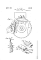
;i[n. t-he;zaccompanying drawings 1 rFig; lie 21: irontzelevation of the moldwheel andtdriving pinionaofi a line; casting machine of well known form, the mold wheeli being equipped :With molds embodying the present invention; r :"Fig. 2 is -a section taken transversely through one ofthe molds; l
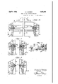
JFigp 3 is a fragmentary View 1 of "the mold onan enlarged-scale and partly in section, showing *the mold elements "in casting-rela tion and a type'bar cast therein; 7
Fig'l'el isa view similar to'Fig. 3 but showing the 'moldelements partially spread apart to separateithe type-bar therefrom;' Z Fig.5 is a View similar to Fig. 4 butfshowing the mold element spread apart to a iurth er extent to completely separate the type bartherefrom; v
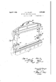
Fig. 6 --isa section: taken longitudinally through .themold in a plane parallel =tosthe casting cavity: ther-ein,=one of the liners be-i 111g shown partly in section;
Fig. Tis a collective View showing the parts or elements of thednold inperspective Figs. 8 and 9 are perspective viewsof liners of-modifiedform; Fig. 10 is a'perspective' View of a portio of a type bar of the'form cast in a mold of theconstructionshOvvn; and
Fig} 11 is a perspective view of "a portion of: ejection from a mold embodying #the-presi ent invention. 1
Similar parts arede'signated the same reference characters in the diflerent "figures.
The invention is shown in 'the present instance applied to a mold of the-"kind used in line casting'machines of the "class shown-and" described in the TMergenth'aler -patent re ferred to, '1 representing the rotatablemold Wheel commonly used insuch machines and 2 representing the pinion usually-employed to-rotate the mold wheel to bring the] mold thereon in use into casting position 'and to' then carry the moldcontamlng the type bar cast therein to ejecting position where the type'bar is removed f rom the 1nold-,' the means for thus rotating the moldzwheel'being Well understood in the art so that-illustration: and further description thereof is deemed unnece essaryp The 1molclxwheelis: providedrwigth: recesses or pockets 4 in which the molds are mounted, it being understood that any desired number of molds may be applied to the mold wheel and any of which may be used for the casting of the type bars.
The mold, according to the present invention, comprises a mold body 5 which is secured to the mold wheel in fixed relationship therewith by the screws 6 or other suitable means, the face of the mold body having the usual alining grooves 7 to receive the lower rear lugs or ears on the matrices of a matrix line presented to the face of the mold, a cap 8 which is mounted opposite to the mold body, and a pair of liners 9 and 9 which are interposed between the ends of the mold cap and mold body, the thickness of these liners defining the height of the mold cavity or slot 10 in which the type bars are cast, the liners closing the ends of said cavity.
The casting faces of the mold body and mold cap as shown, are formed with ribs or projections 11 which extend toward one another or into the casting cavity and produce longitudinal grooves a and adjacent ribs on the sides of the type bar A (Fig. 10) adjacent to the type face 5 of the type bar, such type bar being like those shown and described for example in U. S. Letters Patents, Nos. 1,122,819 granted December 29, 191 1, to G. T. Trundle, and 1,615,031 granted January 18, 1927, to J. C. Norwood et al., the typebearing portion being broken or separated from the body portion along the thin neck d, although it will be understood that the casting face of one of the mold members, such as the mold cap may be so formed as to produce a type bar like the type bar A (Fig. 11) having an interrupted shoulder a extending longitudinally along a side thereof which produces portions 011 the body of the type bar of greater thickness than the character bearing edge I), or the casting faces of the mold body and mold cap may be substantially smooth and parallel as in molds commonly used for casting ordinary type bars.
The mold cap 8 is movable toward and from the mold body 5, and in order to guide the mold cap in its movements, it is provided with depending arms or guide posts 12 which are rigidly secured thereto at its ends and fit slidably in slots 13 formed in the ends of the mold body. The liners 9 and 9 are also movable toward and from the mold body, the liner 9 having recesses 14 therein to receive the heads of screws 15 which latter are shouldered. and threaded into the mold body, and the liner 9 having a recess 16 therein to receive the head of a shouldered screw 17 which latter is threaded into the mold body, the heads of the screws in these liners allowing the liners to separate or move upwardly from the mold body to a limited extent, and the liners have portions which overhang the inner walls of the slots 13 in the respective ends of the mold body and project into recesses 18 which are formed in the inner sides of the guide posts 12, the lower ends of these recesses forming shoulders 19 which are adapted to engage the under sides of the liners and to lift them from the mold body after the mold cap has separated from the mold body to a given extent. One of the liners, as the liner 9, is movable in a direction longitudinally of the mold in order to compensate for expansion and contraction of the mold parts due to heating thereof by the type metal, this liner containing springs 20 which are interposed between it and blocks 21 fixed to the adjacent end of the mold body, these springs acting to force this liner toward the mold cavity and thereby seal the adjacent end of the mold cavity, preventing the entrance of metal at the joints between the liners and the mold cap and body, the construction of this movable liner being similar to that shown and described in U. S. Letters Patent No. 1,684,360 granted Sept. 11, 1928, to J. C. Norwood.
The inner ends of the liners are provided with means for supporting the ends of a type bar cast in the mold cavity. As shown in Figs. 1 to 7 inclusive, the inner ends of the liners are formed with grooves 22 and 23 which extend in a forward direction, these grooves forming ribs or ledges c on the respective ends of the type bar A cast in the mold cavity, and when the liners are lifted or otherwise separated from the mold body, they will support the type bar, as shown for example in Fig. 4. Instead of forming the inner ends of the liners with grooves, they may be formed with inwardly projecting ribs 22 and 23 as shown in Figs. 8 and 9 and these ribs on the liners will then form grooves c on the respective ends of the type bar, as shown in Fig. 11, so that when the liners are lifted or separated from the mold body they will support the type bar at its ends and in separated relation with the mold body. These supporting grooves or ribs on the inner ends of the liners will not only support the type bar in separated relation with the mold body but they will also guide the type bar while it is being pushed forwardly through and ejected from the mold by the ejector. These grooves or ribs extend toward the front of the mold and they may be parallel to one another, and the grooves 22 and 23 may be tapered so as to enlarge toward the front of the mold or the ribs 22 and 23 may be tapered so as to diminish in size toward the front of the mold and thereby relieve friction between them and the ends of the type bar during ejection thereof.
Means is provided for firmly holding the mold cap and liners in fixed relation with the mold body during the casting operation. the mold cap being shown in the present instance provided with a cam 24: which is fixed theresmooth sides, a very small opening movement of the mold cap relatively to the mold body will be sutlicient to separate the type bar from the casting faces of the mold cap and body and thus relieve the type bar of friction against the casting faces of the mold during ejection of the type bar therefrom.
The present invention provides a mold which may be applied to line casting machines of usual construction without change or interference with cooperating parts commonly used on such machines, and which enables the type bars or slugs cast therein to be ejected with greater ease and facility than heretofore. By mounting the mold cap and liners so that they may be spread apart relatively to each other and to the mold body, and providing the liners with grooves, ribs or equivalent means for supporting the type bar and for guiding it for ejection from the mold, the type bar cast in the mold is freed and separated from the mold body and mold cap when the latter is lifted or spread, thereby relieving the type bar of friction or other resistance to ejection from the mold body and cap, and by supporting the type bar in ejecting position within the mold cavity by the engagement of the liners with its ends, the only resistance to the ejection of the type bar is that due to the friction between its ends and the liners, which is relatively small, so the type bar may be ejected very easily.
The invention is particularly advantageous when applied to molds of the class employed for casting type bars of the well known kind, having longitudinal retaining grooves for mounting them in the grooved or slotted drum or other type holding form of a printing machine of well known construction or for casting type bars having interrupted longitudinal grooves in a side thereof or shoulders projecting from the body thereof so that portions of the bodies of the type bars have a greaterthickness than that of the character bearing edge thereof, the relative spreading of the mold cap and liners relatively to each other and to the mold body freeing the interengaging portions of the type bar and the casting faces of the mold so that there will be no obstruction to the forward edgewise ejection of the type bar therefrom.
I claim as my invention 1. A mold for line casting machines comprising opposed members relatively movable toward and from one another, liners between said members and means for relatively moving said liners away from each of said members.
2. A mold for line casting machines comrising opposed members guided to move relatively toward and from one another and forming a casting cavity between them, and liners between said members and defining the ends of said cavity, said liners being relatively movable toward and from each of said members, and one of said members having means for moving the liners away from the other member.
3. A mold for line casting machines comprising opposed members and interposed liners forming a casting cavity, and means for moving one of said members toward and from the other member and the liners, the liners being movable toward and from said other member.
4. A mold for line casting machines comprising opposed members and interposed liners forming a casting cavity, means for moving one of said members toward and from the other member and the liners, the liners being movable toward and from said other member, and limit means permitting separation of the movable member and the liners to relatively different extents with respect to said other member.
5. A mold for line casting machines comprising opposed members relatively movable toward and from one another and forming a type bar casting cavity between them, and liners between said members and having means thereon for supporting at its end a type bar cast in said cavity and for guiding such type bar for ejection therefrom when said mold members are relatively separated.
6. A mold for line casting machines comprising opposed members forming a type bar casting cavity between them, and liners between said members and having means thereon for supporting a type bar cast in said cavity and for guiding such type bar for ejection therefrom, the liners being movable in a direction from one of said members and the other member being movable in a direction from the liners.
7 A mold for line casting machines comprising opposed members forming casting faces between them, and liners between said members and having type bar supporting portions thereon, one of said members and the liners being relatively movable toward and from each other and the other member.
8. A mold for line casting machines comprising opposed members forming a type bar casting cavity between them, and liners between said members and defining the ends of said cavity and having portions to form supports for the ends of a type bar cast in said cavity, one of said members and the liners being relatively movable toward and from each other and the other member.
9. A mold for line casting machines C0111- prising opposed members forming a type bar casting cavity between them, and liners between said members and having portions on their inner ends to support the ends of a type bar cast in sai d cavity and to guide such type bar for ejection therefrom, one of said members being movable in a direction from the other member and having means for moving the liners in a direction from said other memrate it from the typebar.
10. A moldforline casting machines comprising a mold body and cap forminga cavity between them for casting a type barthere in, liners between-said body and cap and closing the ends of said cavity, said liners havin ortions ontheir inner ends to su ort a type bar cast in said cavity and to guide it for ejection therefrom, the cap being movable toward and from the. mold body and the liners being movable transversely between the cap and body. e
11. A mold for linecasting machines comprising a mold body and cap forming a cavity between them for casting a type bar therein, liners between said body and cap and having portions for supporting the ends of a type bar cast in said cavity and for guiding such type bar for ejection therefrom, and members on the cap for guiding it to move toward 7 and from the body, said members having portions thereon to engage the liners and to move them away from the mold body.
12. A mold for line casting machines comprising a mold body and cap, liners between the body and cap, the liners being movable toward and from the mold body and having means for limiting their movement in a direction from the body, and the cap being movable toward and from the mold body and liners and havingmeans to engage the liners to move them from the body and to limit the movement of the cap from the liners and mold body.
In testimony whereof I have hereunto set my hand.
SAMUEL E. SPERRY.
Priority Applications (1)
| Application Number | Priority Date | Filing Date | Title |
|---|---|---|---|
| US487585A US1852985A (en) | 1930-10-09 | 1930-10-09 | Mold for line casting machines |
Applications Claiming Priority (1)
| Application Number | Priority Date | Filing Date | Title |
|---|---|---|---|
| US487585A US1852985A (en) | 1930-10-09 | 1930-10-09 | Mold for line casting machines |
Publications (1)
| Publication Number | Publication Date |
|---|---|
| US1852985A true US1852985A (en) | 1932-04-05 |
Family
ID=23936340
Family Applications (1)
| Application Number | Title | Priority Date | Filing Date |
|---|---|---|---|
| US487585A Expired - Lifetime US1852985A (en) | 1930-10-09 | 1930-10-09 | Mold for line casting machines |
Country Status (1)
| Country | Link |
|---|---|
| US (1) | US1852985A (en) |
-
1930
- 1930-10-09 US US487585A patent/US1852985A/en not_active Expired - Lifetime
Similar Documents
| Publication | Publication Date | Title |
|---|---|---|
| US1852985A (en) | Mold for line casting machines | |
| US2097711A (en) | Matrix composing and line casting machine | |
| US2685959A (en) | Slug-trimming knife fob line casting | |
| US1742981A (en) | Type slug | |
| US2082532A (en) | Mold of typographical slug casting machines | |
| US2035421A (en) | Vise jaws for typographical machines | |
| US2007951A (en) | Slug casting machine | |
| US2242178A (en) | Typographical slug casting machine | |
| US3071242A (en) | Matrix for line-casting machine | |
| US3127983A (en) | Self cleaning spaceband for type casting machines | |
| US1941741A (en) | Typographical line-casting machine | |
| US1567857A (en) | Typographical machine | |
| US2214888A (en) | Slug casting machine | |
| US2046301A (en) | Slug casting mold | |
| US2198370A (en) | Ejector for slug casting machines | |
| US672199A (en) | Mold of linotype-machines. | |
| US757648A (en) | Linotype-machine. | |
| US609883A (en) | Office | |
| US1151612A (en) | Slug-casting machine. | |
| US1910567A (en) | Slug casting machine | |
| US689603A (en) | Linotype-machine. | |
| US1372074A (en) | Low-quad mold | |
| US1963585A (en) | Lead for printing presses | |
| US2214887A (en) | Slug casting machine | |
| GB447831A (en) | Improvements in or relating to typographical slug casting machines |