US185297A - Improvement in plows - Google Patents
Improvement in plows Download PDFInfo
- Publication number
- US185297A US185297A US185297DA US185297A US 185297 A US185297 A US 185297A US 185297D A US185297D A US 185297DA US 185297 A US185297 A US 185297A
- Authority
- US
- United States
- Prior art keywords
- plow
- plows
- lever
- rod
- frame
- Prior art date
- Legal status (The legal status is an assumption and is not a legal conclusion. Google has not performed a legal analysis and makes no representation as to the accuracy of the status listed.)
- Expired - Lifetime
Links
- 238000010276 construction Methods 0.000 description 2
- 238000006585 Colvin synthesis reaction Methods 0.000 description 1
Images
Classifications
-
- A—HUMAN NECESSITIES
- A01—AGRICULTURE; FORESTRY; ANIMAL HUSBANDRY; HUNTING; TRAPPING; FISHING
- A01B—SOIL WORKING IN AGRICULTURE OR FORESTRY; PARTS, DETAILS, OR ACCESSORIES OF AGRICULTURAL MACHINES OR IMPLEMENTS, IN GENERAL
- A01B3/00—Ploughs with fixed plough-shares
- A01B3/36—Ploughs mounted on tractors
- A01B3/38—Ploughs mounted on tractors without alternating possibility
Definitions
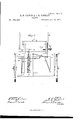
- A represents a horizontal frame, to which the tongue B is attached, and upon which the drivers seat 0 is supported in any suitable manner.
- This horizontal frame A is rigidly secured on top of a vertical frame, D, the lower part of which is, by means of brace-rods a a, connected with the front part of the horizontal frame A. From the sides of the vertical frame D project spindles b 1), upon which the wheels E E are placed.
- rollers G G In suitable boxes on the horizontal frame A are placed two rollers, G G, one in front and the other in rear of the vertical frame D, and these two rollers are provided with arms d d, connected by a From the front roller Gr also projects an arm, f, connected with the plow-beam H near its front end by an adjustable connection made in two parts, I and I, so arranged that said connection can be lengthened or shortened, as required. From the rear roller G extends another arm, h, which is connected with the rear portion of the plow-beam H by a sliding rod, J-that is, a rod made in two parts, and sliding upon each other.
- a sliding rod J-that is, a rod made in two parts, and sliding upon each other.
- a lever, K On one end of the rear roller G is attached a lever, K, by means of which the two rollers are operated so as to raise and lower the plow-beam, as required.
- a suitable ratchet-plate is to be provided to hold the lever K at any point, and thus sustain the plow at any height desired.
- the plow-beam H passes through a vertical guide-frame, L, pivoted at its lower end to the bottom of the vertical frame D, and held by a guide-wire, 7c, as shown.
- the upper end of the pivoted frame L is, by a rod, 11, connected with one arm of a double crank, M, the other arm of said double crank being by a rod, m, connected with a lever, N, pivoted to the horizontal frame A.
- the lever N is also intended to have fastenings to hold it stationary when desired.
Landscapes
- Life Sciences & Earth Sciences (AREA)
- Engineering & Computer Science (AREA)
- Mechanical Engineering (AREA)
- Soil Sciences (AREA)
- Environmental Sciences (AREA)
- Saccharide Compounds (AREA)
Description
, ZSheets-Sheet l, H. H. COLVIN & I. R. JOHNSON.
FLOWS. N0.185,Z97. Patented Dec.12, 187-6.
. TN 3 ES d) I INE T R M 1 Z5 of M T WTTORNEY HE GRAPHIC CO.N.Y
QShgets-Sheet'Z. H. H. COLVIN & I. R. JOHNSON.
PLoWs. No.185,29.7. Patented Dec. 12, I876.
IL m W W i 72/ M g 7; (11) E MAN 17 '2 L L E O Q ATTORNEYS N.PEiEqS, PHOTD -LITHOGRAPHER, WASHINGTON. D c.
' rod or link, 6, as shown.
UNITED ATEN'I QFFECE.
HANNIBAL H. OOLVIN AND ISAAC R. JOHNSON, OF WVINFIELD, IOWA.
IMPROVEMENT IN PLOWS.
Specification forming part of Letters Patent No. 185,297, dated December 12, 1876; application filed October 12. 1876.
To all whom it may concern:
Be it known that we, HANNIBAL H. COL- VIN and ISAAC R. JOHNSON, of Winfield, in the county of Henry, and in the State of Iowa, have invented certain new and useful Improvements in Flows; and do hereby declare that the following is a full, clear, and exact description thereof, reference being bad to the accompanying drawings, and to the letters of reference marked thereon, making a part of this specification.
The nature of our invention consists in the construction and arrangement of a carriage for sulky-plows, as will be hereinafter more fully set forth.
In order to enable others skilled in the art to which our invention appertains to make and use the same, we will now proceed to describe its construction and operation, referring to the annexed drawing, in which- Figure l is a vertical section of our invention. Fig. 2 is a plan view; and Fig. 3, a
. rear elevation of the same.
A represents a horizontal frame, to which the tongue B is attached, and upon which the drivers seat 0 is supported in any suitable manner. This horizontal frame A is rigidly secured on top of a vertical frame, D, the lower part of which is, by means of brace-rods a a, connected with the front part of the horizontal frame A. From the sides of the vertical frame D project spindles b 1), upon which the wheels E E are placed. In suitable boxes on the horizontal frame A are placed two rollers, G G, one in front and the other in rear of the vertical frame D, and these two rollers are provided with arms d d, connected by a From the front roller Gr also projects an arm, f, connected with the plow-beam H near its front end by an adjustable connection made in two parts, I and I, so arranged that said connection can be lengthened or shortened, as required. From the rear roller G extends another arm, h, which is connected with the rear portion of the plow-beam H by a sliding rod, J-that is, a rod made in two parts, and sliding upon each other. On one end of the rear roller G is attached a lever, K, by means of which the two rollers are operated so as to raise and lower the plow-beam, as required. A suitable ratchet-plate is to be provided to hold the lever K at any point, and thus sustain the plow at any height desired. The plow-beam H passes through a vertical guide-frame, L, pivoted at its lower end to the bottom of the vertical frame D, and held by a guide-wire, 7c, as shown. The upper end of the pivoted frame L is, by a rod, 11, connected with one arm of a double crank, M, the other arm of said double crank being by a rod, m, connected with a lever, N, pivoted to the horizontal frame A.
By these means the plow is easily tilted to the right or left to avoid obstructions. The lever N is also intended to have fastenings to hold it stationary when desired.
In operation the sliding rod J at the back is pressing down, and when the lever is used to raise the plow out of the ground it raises the front of the beam first until the plow is out of the ground, and then lifts it straight up.
Having thus fully described our invention, what we claim as new, and desire to secure by Letters Patent, is-- 1. The combination of the rigid frames A D, the plow-beam H, pivoted frame L, rod 6, double-crank M, rod on, and lever N, substantially as and for the purposes herein set forth.
2. The combination of the frames A D, connected rollers G G, arms fh, adjustable connection I I, sliding connection J, plow-beam H, and lever K, substantially as and for the purposes herein set forth.
In testimony that we claim the foregoing we have hereunto set our hands this 1st day of September, 1876.
HANNIBAL H. GOLVIN. ISAAG R. JOHNSON. Witnesses:
O. L. EVERT, WM. G. LANDER.
Publications (1)
| Publication Number | Publication Date |
|---|---|
| US185297A true US185297A (en) | 1876-12-12 |
Family
ID=2254702
Family Applications (1)
| Application Number | Title | Priority Date | Filing Date |
|---|---|---|---|
| US185297D Expired - Lifetime US185297A (en) | Improvement in plows |
Country Status (1)
| Country | Link |
|---|---|
| US (1) | US185297A (en) |
-
0
- US US185297D patent/US185297A/en not_active Expired - Lifetime
Similar Documents
| Publication | Publication Date | Title |
|---|---|---|
| US185297A (en) | Improvement in plows | |
| US149140A (en) | Improvement in wheel-plows | |
| US120073A (en) | Improvement in cultivators | |
| US131218A (en) | Improvement in gang-plows | |
| US151656A (en) | Improvement in scrapers | |
| US329819A (en) | Thomas h | |
| US166636A (en) | Improvement in cultivators | |
| US608696A (en) | Gang-plow | |
| US196393A (en) | Improvement in sulky-harrows | |
| US136131A (en) | Improvement in sulky-harrows | |
| US56295A (en) | Improvement in cultivators | |
| US161645A (en) | Improvement in riding attachments for plows | |
| US199153A (en) | Improvement in sulky-plows | |
| US137044A (en) | Improvement in wheel-plows | |
| US134121A (en) | Improvement in sulky-plows | |
| US82562A (en) | strotjd | |
| US141913A (en) | Improvement in land-markers | |
| US111366A (en) | Improvement in sulky-plows | |
| US59654A (en) | Improvement in sulky-plows | |
| US234328A (en) | abrahams | |
| US223186A (en) | Improvement in sulky-plows | |
| US380285A (en) | Cultivator | |
| US58395A (en) | Improvement in plows | |
| US222534A (en) | Improvement in wheel-plows | |
| US191588A (en) | Improvement in sulky-plows |