US1852937A - Auger bit - Google Patents
Auger bit Download PDFInfo
- Publication number
- US1852937A US1852937A US496576A US49657630A US1852937A US 1852937 A US1852937 A US 1852937A US 496576 A US496576 A US 496576A US 49657630 A US49657630 A US 49657630A US 1852937 A US1852937 A US 1852937A
- Authority
- US
- United States
- Prior art keywords
- bit
- extension
- groove
- face
- cutter
- Prior art date
- Legal status (The legal status is an assumption and is not a legal conclusion. Google has not performed a legal analysis and makes no representation as to the accuracy of the status listed.)
- Expired - Lifetime
Links
- 238000005520 cutting process Methods 0.000 description 10
- 230000004048 modification Effects 0.000 description 1
- 238000012986 modification Methods 0.000 description 1
Images

Classifications
-
- B—PERFORMING OPERATIONS; TRANSPORTING
- B27—WORKING OR PRESERVING WOOD OR SIMILAR MATERIAL; NAILING OR STAPLING MACHINES IN GENERAL
- B27G—ACCESSORY MACHINES OR APPARATUS FOR WORKING WOOD OR SIMILAR MATERIALS; TOOLS FOR WORKING WOOD OR SIMILAR MATERIALS; SAFETY DEVICES FOR WOOD WORKING MACHINES OR TOOLS
- B27G15/00—Boring or turning tools; Augers
-
- Y—GENERAL TAGGING OF NEW TECHNOLOGICAL DEVELOPMENTS; GENERAL TAGGING OF CROSS-SECTIONAL TECHNOLOGIES SPANNING OVER SEVERAL SECTIONS OF THE IPC; TECHNICAL SUBJECTS COVERED BY FORMER USPC CROSS-REFERENCE ART COLLECTIONS [XRACs] AND DIGESTS
- Y10—TECHNICAL SUBJECTS COVERED BY FORMER USPC
- Y10T—TECHNICAL SUBJECTS COVERED BY FORMER US CLASSIFICATION
- Y10T408/00—Cutting by use of rotating axially moving tool
- Y10T408/86—Tool-support with means to permit positioning of the Tool relative to support
- Y10T408/87—Tool having stepped cutting edges
- Y10T408/8738—Tool having stepped cutting edges including inverse cutting edge
-
- Y—GENERAL TAGGING OF NEW TECHNOLOGICAL DEVELOPMENTS; GENERAL TAGGING OF CROSS-SECTIONAL TECHNOLOGIES SPANNING OVER SEVERAL SECTIONS OF THE IPC; TECHNICAL SUBJECTS COVERED BY FORMER USPC CROSS-REFERENCE ART COLLECTIONS [XRACs] AND DIGESTS
- Y10—TECHNICAL SUBJECTS COVERED BY FORMER USPC
- Y10T—TECHNICAL SUBJECTS COVERED BY FORMER US CLASSIFICATION
- Y10T408/00—Cutting by use of rotating axially moving tool
- Y10T408/86—Tool-support with means to permit positioning of the Tool relative to support
- Y10T408/875—Tool-support with means to permit positioning of the Tool relative to support including means to "form" depression in work
-
- Y—GENERAL TAGGING OF NEW TECHNOLOGICAL DEVELOPMENTS; GENERAL TAGGING OF CROSS-SECTIONAL TECHNOLOGIES SPANNING OVER SEVERAL SECTIONS OF THE IPC; TECHNICAL SUBJECTS COVERED BY FORMER USPC CROSS-REFERENCE ART COLLECTIONS [XRACs] AND DIGESTS
- Y10—TECHNICAL SUBJECTS COVERED BY FORMER USPC
- Y10T—TECHNICAL SUBJECTS COVERED BY FORMER US CLASSIFICATION
- Y10T408/00—Cutting by use of rotating axially moving tool
- Y10T408/86—Tool-support with means to permit positioning of the Tool relative to support
- Y10T408/885—Tool-support with means to permit positioning of the Tool relative to support including tool-holding clamp and clamp actuator
-
- Y—GENERAL TAGGING OF NEW TECHNOLOGICAL DEVELOPMENTS; GENERAL TAGGING OF CROSS-SECTIONAL TECHNOLOGIES SPANNING OVER SEVERAL SECTIONS OF THE IPC; TECHNICAL SUBJECTS COVERED BY FORMER USPC CROSS-REFERENCE ART COLLECTIONS [XRACs] AND DIGESTS
- Y10—TECHNICAL SUBJECTS COVERED BY FORMER USPC
- Y10T—TECHNICAL SUBJECTS COVERED BY FORMER US CLASSIFICATION
- Y10T408/00—Cutting by use of rotating axially moving tool
- Y10T408/89—Tool or Tool with support
- Y10T408/901—Having axially extending peripheral cutting spur
Definitions
- My invention relates to auger bits,: and particularly to extension bits and'to scribing mechanism in combinationtherewith.
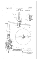
- Figure 6 isa section on the line 6-'6 therer
- Figure 7 is a section on the line 7-.-7 thereof showing the scale on the scribe;
- Figure 8 is a rear elevation of the extension cutter showing its non-slipping,'corrugated face
- Figure 9 is a section on the line 99 of Figure 3 looking in the direction of the arrows and showing the non-slipping face having corrugations on the shouldered groove for receiving the corrugated face of the extension member so that such corrugations interlock and prevent relative movement.
- 1 is the shank of the shaft 2ofa bit having the expanded head 3 which has-a diagonally-disposed, flat face 4.
- Ashoulder'5 is provided at right angles to the face forming a 'diagonally-dispose'd extension 6 through the under face of which 7 projects the retaining screw 8 that may be adjusted through the slot 7 9 above theup'per surface 5 of the projection 6 whichcarries the screw 8.
- the lower face 17 of this cutter engages the sloping surface 15' and the corrugated face 18 of the extension cutter engagesthe corrugated face 13 of thebit.
- the upper sloping face 19 of the cutter engages the chips, elevatesthemand "discharges them either into the groovell or freely to a point behind the cutter into the hole being cut.
- the upper surface 19 is alsoeen-v gaged by the nose of the set screw'8 which thus forces the extension cutter downwardly on the surface 15 and laterally against'the corrugated surface 13 tohold itin position.
- the extension cutter is provided with a cutting lip 20.
- This cutting lip may also act as a scribe as the point of the cutting lip 20 is located above the entering screw'21 carried on the extreme end of the bit.
- the extension cutter 16 is provided with a scale 22 to facilitate the setting of-the extension cutter to cut a hole of given dimensions.
- a scribing tool consisting of an arcuate body 24and-ja depending scribing nose 25 is provided.
- V This scribe has aface'26 and a face 27 at anglesto one anotheradapted' to-fit against Y the faces 13 and 15 and be held in position by The head 8 is continued, as at 10, on the 7 the set screw 8 which engages the arcuate corner 28 of the scribing implement.
- a scale 29 indicates the diameter of the circle desired to be enscribed.
- the bit is further provided with the usual stationary cutting lip 30 which cooperates in the cutting operation.
- a bit having an angular groove, the bottom of which is inclined to the axis of the bit, a set screw carried by said bit extending into said groove at right angles to the bottom thereof, and an extension cutter carried in said groove having an upper face inclined to its lower face, the upper face of which is engaged by said set screw whereby the angular extension cutter is forced upward and inwardly in said groove.
- a bit having an angular groove with a wall and a bottom inclined to the axis of the bit and at a right angle to the wall, a set screw carried by said bit extending into said groove at right angles to the bottom thereof, and an extension cutter carried in said groove having an upper face inclined to its lower face, the upper face of which is engaged by said set screw whereby the angular extension cutter is forced upwardly and inwardly in said groove, said groove having its vertical wall engaged by avertical face of said extension member.
- a bit having an angular groove with a wall and a bottom inclined to the axis of the bit and at a right angle to the wall, a set screw carried by said bit extending into said groove at right angles to the bottom thereof, and an extension cutter cartied in said groove having an upper face inclined to its lower face, the upper face of which is engaged by said set screw whereby the angular extension cutter is forced upwardly and inwardly in said groove, said extension member having a vertical corrugated face for engaging the vertical wall of the eve.
- a hit an offset head thereon having a screw tilted to the axis of the bit, a set screw mounted therein at an angle to the axis of the bit, said offset head having an angular groove receivin the end of said set screw, and a triangular-in-section extension cutter mounted in said groove, one face of which is engaged by said set screw, an entering screw in said offset head below said extension cutter, a cutting lip on the end of the extension cutter, cutting lips on said head of the bit oppositely disposed from one another on opposite sides of said entering screw, and corrugated means between said extension cutter and said groove on the head for preventing lateral slipping of said cutter in the head.
- a bit a laterallydisposed head thereon, an offset lug on said head, a set screw therein at an angle to the axis of the bit, said head having a transverse slot into which said screw projects, said slot having a wall slightly inclined to the axis of the screw and a wall at right angle to the first-named wall, and a triangular-shaped, laterally-extending extension member in said groove, two faces of which engage the walls of said slot at right angles to one another, and the third face of which forms a wedge engaging with the end of said screw.
- a bit In combination, a bit, a laterally-disposed head thereon, an offset lug on said head, a. set screw therein at an angle to the axis of the bit, said head having a transverse slot into which said screw projects, said slot having a wall slightly inclined to the axis of the screw and a wall at right angle to the firstnamed wall, and a triangular-shaped, laterally-extending extension member in said groove, two faces of which engage the walls of said slot at right angles to one another, and the third face of which forms a wedge engaging with the end of said screw, and corrugated means between said slot and said extension member for preventing lateral movement of the extension member in the slot.
- a head having a spiral groove and an extension cutter seat, said seat having a pair of right angularly disposed walls, one of said walls being inclined to the horizontal, a triangular extension cutter in said seat with two sides engaging the walls of the seat, and a third side in line with the spiral groove and a screw at right angles to the horizontally inclined side to hold the extension cutter in the seat.
Landscapes
- Life Sciences & Earth Sciences (AREA)
- Engineering & Computer Science (AREA)
- Mechanical Engineering (AREA)
- Wood Science & Technology (AREA)
- Forests & Forestry (AREA)
- Excavating Of Shafts Or Tunnels (AREA)
Description
' April 5, '1932. c. B. ROBINSON AUGER BIT Filed Nov. 19, 1950 2Sheets-5het 1 FIG/I- INVEN'TDR 6/04/6155 19. EOB/A'ffl/ Y! Z B I ATTDRNEY? April '5, 1932. c. B. ROBIINSON AUGER BI T Filed Nov. 19, 1950 2 Sheets-Sheet 2 2 INV |\\\\\\\\\\\\\\\\\\.\\\\\\\\\\\\\\\\\\\d (my 6.22210 Mzw ATTORNEYq Patented Apr. '5, 1 932 I UNITEDstares PATENT- m onAnrEs enonrnson, OFwWILMINGTON; oHI 'AssIGNOR TO THE IRWIN AUG-ERBIT COMPANY, or -WILMINGTOLN, onro, AooRroRA'rroN or; OHIO AUGER BIT Application f led November 19, 1930. Serial No. 496,576. 1
My invention relates to auger bits,: and particularly to extension bits and'to scribing mechanism in combinationtherewith.
It is'the object of my invention to provide if i a combined extension bit and scribing mechanism'. I
It isa further object to vprovide an extension bit in which anextension cutter can be held in rigid engagement with the bit; in which the extension member is so arranged that it may be quickly adjusted and held adjusted by a single set screw; in Whichthe ex- 1 tension member will easily lift the chips as they are out by the cutting lip and discharge 0 those chips into the hole which is being cut and when they have accumulated a sufficient depth discharge the chips through a spiral groove that will: serve to lift the chips out of the hole., 4
" It is afurther object to provide that 'thei surface of the extension cutter over which, the chips move is, incommunicationwlth the Chip-removing groove.
i "It is my object tofprovide an'interchange- Referring tothe drawings:
able extension cutter and scribe with'a commounted in the place of the extension cutter;
Figure 6 isa section on the line 6-'6 therer Figure 7 is a section on the line 7-.-7 thereof showing the scale on the scribe;
Figure 8 is a rear elevation of the extension cutter showing its non-slipping,'corrugated face;
Figure 9 is a section on the line 99 of Figure 3 looking in the direction of the arrows and showing the non-slipping face having corrugations on the shouldered groove for receiving the corrugated face of the extension member so that such corrugations interlock and prevent relative movement.
Referring to the drawingsin detail, 1 is the shank of the shaft 2ofa bit having the expanded head 3 which has-a diagonally-disposed, flat face 4. Ashoulder'5 is provided at right angles to the face forming a 'diagonally-dispose'd extension 6 through the under face of which 7 projects the retaining screw 8 that may be adjusted through the slot 7 9 above theup'per surface 5 of the projection 6 whichcarries the screw 8. I
face of which is I formed a chip groove 11. Below the chipgroove is anextension 12 that is cut away to forma 'face' 13 that is corrugated as at 14c and a diagonally-disposed surface 1 15, both of which faces support and engage the. lateral extension cutter generally designated 16. V
The lower face 17 of this cutter engages the sloping surface 15' and the corrugated face 18 of the extension cutter engagesthe corrugated face 13 of thebit. I The upper sloping face 19 of the cutter engages the chips, elevatesthemand "discharges them either into the groovell or freely to a point behind the cutter into the hole being cut. The upper surface 19 is alsoeen-v gaged by the nose of the set screw'8 which thus forces the extension cutter downwardly on the surface 15 and laterally against'the corrugated surface 13 tohold itin position.
The extension cutter is provided with a cutting lip 20. This cutting lip mayalso act as a scribe as the point of the cutting lip 20 is located above the entering screw'21 carried on the extreme end of the bit.
The extension cutter 16 is provided with a scale 22 to facilitate the setting of-the extension cutter to cut a hole of given dimensions.
In the event that it isdesired to enscribe a 1 larger circle, such as the circle 23, a scribing tool consisting of an arcuate body 24and-ja depending scribing nose 25 is provided. a
V This scribe has aface'26 and a face 27 at anglesto one anotheradapted' to-fit against Y the faces 13 and 15 and be held in position by The head 8 is continued, as at 10, on the 7 the set screw 8 which engages the arcuate corner 28 of the scribing implement.
A scale 29 indicates the diameter of the circle desired to be enscribed.
The bit is further provided with the usual stationary cutting lip 30 which cooperates in the cutting operation.
It will be understood that I desire to comprehend within my invention such modifications as may be necessary to adapt it to varying conditions and uses.
Having thus fully described my invention, what I claim as new and desire to secure by Letters Patent, is:
1. In combination, a bit having an angular groove, the bottom of which is inclined to the axis of the bit, a set screw carried by said bit extending into said groove at right angles to the bottom thereof, and an extension cutter carried in said groove having an upper face inclined to its lower face, the upper face of which is engaged by said set screw whereby the angular extension cutter is forced upward and inwardly in said groove.
2. combination, a bit having an angular groove with a wall and a bottom inclined to the axis of the bit and at a right angle to the wall, a set screw carried by said bit extending into said groove at right angles to the bottom thereof, and an extension cutter carried in said groove having an upper face inclined to its lower face, the upper face of which is engaged by said set screw whereby the angular extension cutter is forced upwardly and inwardly in said groove, said groove having its vertical wall engaged by avertical face of said extension member.
3. In combination, a bit having an angular groove with a wall and a bottom inclined to the axis of the bit and at a right angle to the wall, a set screw carried by said bit extending into said groove at right angles to the bottom thereof, and an extension cutter cartied in said groove having an upper face inclined to its lower face, the upper face of which is engaged by said set screw whereby the angular extension cutter is forced upwardly and inwardly in said groove, said extension member having a vertical corrugated face for engaging the vertical wall of the eve.
41. In combination, a hit, an offset head thereon having a tilted screw supporting lug, a set screw mounted therein at an angle to the axis of the bit, said offset head having an angular groove for receiving the end of said set screw, and a triangular-in-section extension cutter mounted in said groove, one
face of which is engaged by said set screw, an entering screw in said offset head below said extension cutter, and a cutting lip on the end of the extension cutter, and a cutting lip on said head of the bit oppositely disposed from one another on opposite sides of Said entering screw.
5. In combination, a hit, an offset head thereon having a screw tilted to the axis of the bit, a set screw mounted therein at an angle to the axis of the bit, said offset head having an angular groove receivin the end of said set screw, and a triangular-in-section extension cutter mounted in said groove, one face of which is engaged by said set screw, an entering screw in said offset head below said extension cutter, a cutting lip on the end of the extension cutter, cutting lips on said head of the bit oppositely disposed from one another on opposite sides of said entering screw, and corrugated means between said extension cutter and said groove on the head for preventing lateral slipping of said cutter in the head.
6. In combination, a bit, a laterallydisposed head thereon, an offset lug on said head, a set screw therein at an angle to the axis of the bit, said head having a transverse slot into which said screw projects, said slot having a wall slightly inclined to the axis of the screw and a wall at right angle to the first-named wall, and a triangular-shaped, laterally-extending extension member in said groove, two faces of which engage the walls of said slot at right angles to one another, and the third face of which forms a wedge engaging with the end of said screw.
7'. In combination, a bit, a laterally-disposed head thereon, an offset lug on said head, a. set screw therein at an angle to the axis of the bit, said head having a transverse slot into which said screw projects, said slot having a wall slightly inclined to the axis of the screw and a wall at right angle to the firstnamed wall, and a triangular-shaped, laterally-extending extension member in said groove, two faces of which engage the walls of said slot at right angles to one another, and the third face of which forms a wedge engaging with the end of said screw, and corrugated means between said slot and said extension member for preventing lateral movement of the extension member in the slot.
8. In a bit, a head having a spiral groove and an extension cutter seat, said seat having a pair of right angularly disposed walls, one of said walls being inclined to the horizontal, a triangular extension cutter in said seat with two sides engaging the walls of the seat, and a third side in line with the spiral groove and a screw at right angles to the horizontally inclined side to hold the extension cutter in the seat.
In testimony whereof, I aflix my signature.
CHARLES l3. ROBINSON.
Priority Applications (1)
| Application Number | Priority Date | Filing Date | Title |
|---|---|---|---|
| US496576A US1852937A (en) | 1930-11-19 | 1930-11-19 | Auger bit |
Applications Claiming Priority (1)
| Application Number | Priority Date | Filing Date | Title |
|---|---|---|---|
| US496576A US1852937A (en) | 1930-11-19 | 1930-11-19 | Auger bit |
Publications (1)
| Publication Number | Publication Date |
|---|---|
| US1852937A true US1852937A (en) | 1932-04-05 |
Family
ID=23973245
Family Applications (1)
| Application Number | Title | Priority Date | Filing Date |
|---|---|---|---|
| US496576A Expired - Lifetime US1852937A (en) | 1930-11-19 | 1930-11-19 | Auger bit |
Country Status (1)
| Country | Link |
|---|---|
| US (1) | US1852937A (en) |
Cited By (2)
| Publication number | Priority date | Publication date | Assignee | Title |
|---|---|---|---|---|
| US2618304A (en) * | 1946-12-11 | 1952-11-18 | Robert H Clark | Bit with adjustable cutting blade |
| US20230390834A1 (en) * | 2021-05-14 | 2023-12-07 | L. Curtis Beaton | Method and apparatus for forming a hole |
-
1930
- 1930-11-19 US US496576A patent/US1852937A/en not_active Expired - Lifetime
Cited By (2)
| Publication number | Priority date | Publication date | Assignee | Title |
|---|---|---|---|---|
| US2618304A (en) * | 1946-12-11 | 1952-11-18 | Robert H Clark | Bit with adjustable cutting blade |
| US20230390834A1 (en) * | 2021-05-14 | 2023-12-07 | L. Curtis Beaton | Method and apparatus for forming a hole |
Similar Documents
| Publication | Publication Date | Title |
|---|---|---|
| US476312A (en) | Plug-cutting tool | |
| US1852937A (en) | Auger bit | |
| US1612205A (en) | Guide bushing | |
| US1471866A (en) | Drill | |
| US1474049A (en) | Auger or bit | |
| US1052881A (en) | Nosing-plane. | |
| US451896A (en) | Joseph e | |
| US811769A (en) | Planer-head. | |
| US1056670A (en) | Expansion-bit. | |
| US1056089A (en) | Tool-holder. | |
| US940426A (en) | Auger-bit. | |
| US361522A (en) | Auger-bit | |
| US109244A (en) | Improvement in cutter-heads | |
| US2547325A (en) | Mining machine cutter bit | |
| US81607A (en) | Improvement in slottdig-attger | |
| US658337A (en) | Tool for cutting rivet-heads. | |
| US713001A (en) | Cutting-off tool. | |
| US383289A (en) | Drill-socket | |
| US1108361A (en) | Linotype-matrix. | |
| US1065005A (en) | Miner's drill. | |
| US236511A (en) | Spike | |
| US1427705A (en) | Expanding auger | |
| US1225701A (en) | Underreamer. | |
| US49123A (en) | Improvement in drills for well-boring | |
| US1367087A (en) | Cutting-tool for use in lathes, planing-machines, and the like |