US1852932A - Internal combustion engine - Google Patents
Internal combustion engine Download PDFInfo
- Publication number
- US1852932A US1852932A US699890A US69989024A US1852932A US 1852932 A US1852932 A US 1852932A US 699890 A US699890 A US 699890A US 69989024 A US69989024 A US 69989024A US 1852932 A US1852932 A US 1852932A
- Authority
- US
- United States
- Prior art keywords
- steam
- valve
- oil
- engine
- pipe
- Prior art date
- Legal status (The legal status is an assumption and is not a legal conclusion. Google has not performed a legal analysis and makes no representation as to the accuracy of the status listed.)
- Expired - Lifetime
Links
- 238000002485 combustion reaction Methods 0.000 title description 32
- 239000003921 oil Substances 0.000 description 26
- 210000000038 chest Anatomy 0.000 description 14
- 238000002347 injection Methods 0.000 description 4
- 239000007924 injection Substances 0.000 description 4
- 238000010276 construction Methods 0.000 description 3
- 239000000446 fuel Substances 0.000 description 2
- 238000009434 installation Methods 0.000 description 2
- 239000007921 spray Substances 0.000 description 2
- 241001505295 Eros Species 0.000 description 1
- 101100238516 Rattus norvegicus Mrgprx1 gene Proteins 0.000 description 1
- 238000006243 chemical reaction Methods 0.000 description 1
- 238000004891 communication Methods 0.000 description 1
- 239000000295 fuel oil Substances 0.000 description 1
- 210000004907 gland Anatomy 0.000 description 1
- 238000012423 maintenance Methods 0.000 description 1
- 238000004519 manufacturing process Methods 0.000 description 1
- 230000005906 menstruation Effects 0.000 description 1
- 238000012856 packing Methods 0.000 description 1
- 230000000737 periodic effect Effects 0.000 description 1
- 230000013707 sensory perception of sound Effects 0.000 description 1
- XLYOFNOQVPJJNP-UHFFFAOYSA-N water Substances O XLYOFNOQVPJJNP-UHFFFAOYSA-N 0.000 description 1
- 210000000707 wrist Anatomy 0.000 description 1
Images

Classifications
-
- F—MECHANICAL ENGINEERING; LIGHTING; HEATING; WEAPONS; BLASTING
- F01—MACHINES OR ENGINES IN GENERAL; ENGINE PLANTS IN GENERAL; STEAM ENGINES
- F01L—CYCLICALLY OPERATING VALVES FOR MACHINES OR ENGINES
- F01L13/00—Modifications of valve-gear to facilitate reversing, braking, starting, changing compression ratio, or other specific operations
- F01L13/02—Modifications of valve-gear to facilitate reversing, braking, starting, changing compression ratio, or other specific operations for reversing
-
- F—MECHANICAL ENGINEERING; LIGHTING; HEATING; WEAPONS; BLASTING
- F02—COMBUSTION ENGINES; HOT-GAS OR COMBUSTION-PRODUCT ENGINE PLANTS
- F02B—INTERNAL-COMBUSTION PISTON ENGINES; COMBUSTION ENGINES IN GENERAL
- F02B75/00—Other engines
- F02B75/32—Engines characterised by connections between pistons and main shafts and not specific to preceding main groups
Definitions
- This 'im ention relates to an improyement in internal combustion :QILgIIIQS, particularly :to'the oil leurningwiesel type, and isdirected 'zto ztheipnoVisi-on :off zen improvedconstruction and design ofsnch engines adapted to proem'ote economy in :manufacture: and installation, efficiency and facility in operation and maintenance, and-ineli'eble 1n :performa-nce.
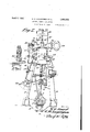
- I 'VVithstheeihoizeiend other ohj'eots iniiiew s which wvifldoe nappazrentxto those skilled :inithe oenteininowel tEea- :airtgthisinventionihlcludes I a d combinations of din atheadramingsgr I : Figure :1 is m wiewvin iront elevzxtion'show sing the general :srrangement i of z-the engme midswnth [one ⁇ of the; cylinders and associated mounting of ⁇ the -parts. Fag 21S zen end elevation :o'fithe engine :andpentrol meelmnismg. r V
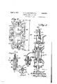
- E gwe -1s a vertical sectional viewithrongh the steainohest and oil pump support.- Eig. V a; better 7 v 5 is a fragmentary sectional View to showthe air supply endsteem exhaust con- ,trol; Fig; (6 is eiseotiona l yiew thrgou'gh. the fuel oilzpuznpend controlvalve.
- Fig. is e fragmentary "sectional view to r that might be: iused.
- I n s'h-ippingni ward extended installation and :use of Diesel poiver, ,and iit qis often desired to make such an installatiomon bound at steamship
- lt-l5 a purpose-of our invention that the neoessary portions for the gDiesel-eontzerslon can he z part-of the complete steam ;plant, and that sufiieient .boilernepaeitymen :be .xretai-ned to ,and (maneuvering the Dieselpnopellereng ne and gtornopfi ia-tionioi thesteem nperatedeuxitlmrles. ln-this may it is possible-to materiallifr'om steam sel.
- the combustion cylinders 26 and 27 have pistons 28 mounted therein on the extensions of the piston rods 14 and 15, to be on the upper sides of the steam pistons 29, in the steam cylinders 1 and 2, these pistons 28 being of less diameter than the pistons 29 by reason of the reduction in the bore of cylinders 26 and 27.
- Water jacket cylinder heads 30 and 31 are secured to close the open tops of combustion cylinders 26 and 27 and it is perhaps preferable that the pistons 28 be provided with re- 1 movable and replaceable heads 32, held. in
- Oil pumps 34 and 35 of any desired type are mounted on standards 36 and 37, which cap and close the open tops of the steam chests 18 and 19, and extensions 38 of the valve stems 21 and 22 are adapted to operate these oil pumps.
- Oil pipes 39 extend from the oil pumps 34 and 35 to the oil spray valves 33, these pipes being preferably coiled or looped to provide for expansion due to the pressure of oil from the pump.
- the supply of oil to the pumps is turned on. and oil through valves 40 operated by the control handle 25, and an overflow pipe 41 has an adjustable overflow or blow-off valve 42 therein to be set to adjust the pressure at which oil is injected.
- One form of such a valve 42 as might be used in this connection is shown in Fig.
- a spring 43 on each stem 43 causes the stem 43 to bear at its lower end against a cam finger 43, which is moved up by the trip 44 carried by stem 38 to raise stem 43 against the pressure of spring 43, and consequently open valve 43.
- the valves 43 can be of the form illustrated in Fig. 6, or of any other suitable type.
- atmospheric air intake pipes 45 having spring-closed suction intake valves 46 and air pipes 47 and 48 lead from the upper and lower ends of the steam chest through pipe 47a to an air chamber 49 which encircles the combustion cylinder to preheat air received from the steam chests.
- a four-way valve 50 is provided in the pipe 470 leading to the air chamber 49, and a pipe 51 leading from any suitable source of compressed air supply is connected with this valve 50, a steam exhaust pipe 52 being also connected with the valve.
- a steam pi pc 54 leads to the steam chests and is controlled by a valve 55, operated by rod 56 having a hand wheel there on.
- Intake ports 57 lead from the air chambers 49 to the combustion chambers of cylinders 26 and 27, at a point above the heads of the pistons 28 on their lower stroke, and exhaust ports 58 are provided through the walls of the cylinders 26 and 27 and open into pipes 59, which connect with the exhaust manifold 60.
- engine valve 50 is set in substantially the relation shown in Figure 5 and valve is open to admit steam to the steam chest 18.
- the control levers are then set for either forward or reverse operation of the steam engine and the pistons in the Diesel cylinders will be reciprocated with the steam pistons 29.
- Valve 50 connects air supply pipe 51 with the chamber 49, and as oil is pumped and is supplied to the combustion chambers by actuation of the steam valves the Diesel units will operate.
- the oil supply can be cut off to permit operation entirely by steam, and the engine can be operated entirely as a Diesel engine, with the steam supply valve 55 closed.
- valve 50 In this setting of the parts the operation In this setting, passage 50?) of valve 50 establishes communlcation from compressed air supply pipe 51 to air chamber 49 and C0111".
- valve 50 can be shifted to bring either passage 50a 'or 50?) to establish direct communication through the two leads of pipe 47a, as illustrated in Fig. 5, and then a direct connection is established from the steam chest through pipes 47 and48.
- the steam pistons 29 act as pump pistons to compress air which is passed through pipes 47 and 48 and through valve 50 tobe discharged into the air chamber 49.
- a reciprocating steam marine engine structure comprising a steam cylinder having a rod carried “piston therein and a stem operated reciprocating steam supply distributing valve, the combination of a combustioncylinder carried by the steam cylinder, a piston carried by the steam piston and working within the combustion cylinder, an atmospheric air intake pipe leading to said steam valve, an air'intake valve in said pipe, a pipe leadingfrom said steam valve to the interior of the combustion cylinder, a valve for said air supply pipe, a reciprocating oil supplypump, an operating means connecting the reciprocating valve to the oil supply pump, and a control valve actuated by movement of the steam supply distributing valve stem t'o eontro'l rperiedic rinjectioms .of foilinto the 'coiribustionzcylinder.
- Vithfa reciprocating steiam Lmarine ens gi ne structure comprising :a steam cylinder having a rod carried piston therein wvith sa stem operated reciprocating steamr distributin'g valve, the combination of an :air inlet the piston rod and valve stem, an internal combustion cylinder mounted in l-inewvithithe connection to the steamrhest, :extensions :on,
- valve rod,-a pipe from the steam ches't to the "combustion cylinder, charge Y supply @connecan oil pump arried by the steam chest to be 'operated tromthe entension of the having a rod carried piston therein with a stem operated reciprocating steam distributmg valve, the combination of extensions on combustion cylinder mounted on the open headend of and in line with the steam cylthe piston rod and valve stem, an internal f inder, a piston carried by the extension of piston to work within said combustion cylinder, anoilE pump carried by the steam valve chest tobe operated from the extension on the valve stem, a pipe from the steam valve chestto the combustion cylinde'rto supply charge forming air to said cylinder, a charge supply connection to the combustion cylinder, a pipe leading from the oil pump to the charge supply connection, a valve in said pipe operated by movement of the extension on the valve stem to open the oil pipe for periodic-injections of oil, a steam connection to the steam valve, and an exhaust connection from said combustion
- a reciprocating steam marine en.- gine structure comprising a steam cylinder having a rod carried piston therein with a the piston rod on the head end of the steam stem operated reciprocating steam distributing valve, the combination of a combustion cylinder of less inder mounted on the open head end of said steam cylinder in axial alinement therewith, a pistonmounted on and reciprocating with the steam piston working within the combustion cylinder, avalve controlled air inlet diameter than the steam cyl' said pump and actuated by movement of the reciprocating steam chest controlling valve to open connection to the combustion cylinder for periodic injections of oil thereinto, and an exhaust connection from the combustion cylinder.
- a reciprocating steam marine engine structure comprising a steam cylinder having a rod carried piston therein and a stem operated reciprocating steam distributing valve
- a- Diesel engine structure comprising an internal combustion cylinder mounted on the open head end of said. stem cylinder in axial alinement therewith, an extension on the steam piston rod extending into the combustion cylinder, a piston carried by the extension of the piston rod movable Within the combustion cylinder, and fuel supply means connecting with said combustion cylinder and connected to be actuated by the steam Valve stem.
Landscapes
- Engineering & Computer Science (AREA)
- Mechanical Engineering (AREA)
- General Engineering & Computer Science (AREA)
- Chemical & Material Sciences (AREA)
- Combustion & Propulsion (AREA)
- Combustion Methods Of Internal-Combustion Engines (AREA)
- Fuel-Injection Apparatus (AREA)
- Electrical Control Of Air Or Fuel Supplied To Internal-Combustion Engine (AREA)
Description
April (1932 G. M. LAGERGREN ET AL 1,852,932
INTERNAL COMBUSTION ENGINE Filed March 17, 1924 gwventou 6562,11; fjlflayei yl'ezz Wad. 4M
3 Sheets-Sheet 1 I April 1932- G. M. LAG ERGREN ET AL INTERNAL COMBUSTION ENGINE Filed March .17 1924 3 Sheets-Sheet 2 June-n on V W65 6'. iii. layeiyl ea @51 April s, 1932.
G. M. LAGERGREN ET AL INTERNAL COMBUSTION ENGINE a Sheets-Sheet 3 Filed March 17,- 1924 Patented Apr. 5; 1932 y .snsr'nv rinensennn ANDWILLIAM emsoom 00 1s," or win-meme; DELAWARE;
mnneoxn s xsonrsrx or sun-WILLIA nrsoom; coxn nnonnsnny INTERNAL COIvIBUS'ItIONYENGINE Application filedjmarhh 17, 1924. fierial No. 4339,8530.
This 'im ention relates to an improyement in internal combustion :QILgIIIQS, particularly :to'the oil leurningwiesel type, and isdirected 'zto ztheipnoVisi-on :off zen improvedconstruction and design ofsnch engines adapted to proem'ote economy in :manufacture: and installation, efficiency and facility in operation and maintenance, and-ineli'eble 1n :performa-nce.
Ellhe primenypohjeet ofthis invention-11s to gzrovide (21111 improvedlengine struetnre operetwith inoderatefcompression :and upon solidzin eetion of :iliel ao'il, Without the 'jnecessity ioi'ma inteiningrzen external supply of high pressure enir, and 10118 which can be (started, zoperetedrand "maneiwered :or controlled, x vzithsthe aid .of low rpressnre air, or
with steam;
,a'eplacement.
- radical xihanges zin 'ztherinstelletionand oon- V r sly decrease theicost ofoonnertmg za steamer r so tures of menstruation; v
qearits Whi'ohrwill he'hereinafteradesoliib ediand :ioonstruetion and A further object of onrimzentionflis :to so eonstruct -iand= armange the stationary end zmo ingwpantszthatthe operating and control ip'ortion's sare :nnder the direct observation of :the operating engineer in charge and are readily f-QIGGQSSlSbl %for;adjnstn1ent,:repair end A still further :type of internal ieonihnstion engine 'ineehaznism which :can' be reedilyazrpplied to end used "in :oongiund 7 on with standard parts of .an :ordinary reciprocating vsteam engine, for nonzvertingzseiidzsteem engine into an internal ,eornhustion: or .Diesektype of engine, without trol of the existing powerplant. e i
I 'VVithstheeihoizeiend other ohj'eots iniiiiew s which wvifldoe nappazrentxto those skilled :inithe oenteininowel tEea- :airtgthisinventionihlcludes I a d combinations of din atheadramingsgr I :Figure :1 is m wiewvin iront elevzxtion'show sing the general :srrangement i of z-the engme midswnth [one {of the; cylinders and associated mounting of {the =-parts. Fag 21S zen end elevation :o'fithe engine :andpentrol meelmnismg. r V
1s a plan View of the engtineishow- :mgthe Jeletwe positlons of lmtelte :and exobject lies in providing 21 give the desired haust walves :and: manifolds, es tvellkas the I,
eonnectio'n 10f LE-H61 pipes rendesteam nndeir 7 'lines; t y
E gwe -1s a vertical sectional viewithrongh the steainohest and oil pump support.- Eig. V a; better 7 v 5 is a fragmentary sectional View to showthe air supply endsteem exhaust con- ,trol; Fig; (6 is eiseotiona l yiew thrgou'gh. the fuel oilzpuznpend controlvalve.
Fig. is e fragmentary "sectional view to r that might be: iused.
I=n s'h-ippingni ward extended installation and :use of Diesel poiver, ,and iit qis often desired to make such an installatiomon bound at steamship where Z -GOHIPlQtQ steam conversion ordinarily requires {a complete {tearing out zof :the steam-propelling engine and ;boilers and ,a 7 replacement of steam winehesaandiother anxil'ierieswvitli electrioeule Fly operated auxiliaries, thus making the -.conyers on cost qoraot oally prohihiti-ve. lt-l5; a purpose-of our invention that the neoessary portions for the gDiesel-eontzerslon can he z part-of the complete steam ;plant, and that sufiieient .boilernepaeitymen :be .xretai-ned to ,and (maneuvering the Dieselpnopellereng ne and gtornopfi ia-tionioi thesteem nperatedeuxitlmrles. ln-this may it is possible-to materiallifr'om steam sel.
In standard :type steam engine su h esisnow installed in many steem propelled vessels, and this ,en :gine'is shown ass-of the two eylinder type. ZDhe engine l oylinders =1 and 2 Jere supported s,byihensuailstanderds guponthe bed 4. The
cranks. 5 and 6 of the engi-ne theioonneeting-rodsl endQfittecLonthe Wrist pins thereof, and at theirnpper lends these rods 8 and 9 7 7 heads 10. endnllimounted Ffor xzertieelreoiproeatery motement in; suitable tsli'de hearings '12'and13 Pp ower to re Diesel propel-led yesthe drawings We I have illustrated ,a.
' Piston rods le end lifiiere roles there is ia tendency to-,-
.plied to the-steam propelling engine forming esteem supply tor starting,
,of vertically reciprocating shatt 17 have are connected with the eross lentis at hand Suche the cross heads and 11 and extend through suitable packing glands 16 in the lower heads 17 of the cylinders 1 and 2. Steam chests 18 and 19 are provided on the cylinders 1 and 2, and the usual slide valves 20 are mounted in these chests to control the intake and exhaust to and from the cylinders. The valves 20 are carried by stems 21 and 22, which have connecting rods 23 and 24 pivotally connected therewith, these connecting rods being mounted on suitable eccentrics on the engine shaft 7. The parts as above described are of substantially standard construction, and are here particularly mentioned only so that the relation and mounting of our improved structure may be better set forth, and the usual steam engine control mechanism is connected with these parts, as shown in Fig. 2, the usual control and operating handle being provided for manipulation by the engineer.
In associating our improved structure with the standard parts and mechanism, we remove the upper heads of the cylinders 1 and 2 and the steam chests 18 and 19, and extend the piston rods 14 and 15 and valve stems 21 and 22. In the open head ends of the cylinders, the combustion cylinders 26 and 27 are mounted, these cylinders being held in place by the usual cap screws, or by any other suitable fastenings. The combustion cylinders have the bore thereof reduced to the proper size for the strength of the engine shaft 7. The combustion cylinders 26 and 27 have pistons 28 mounted therein on the extensions of the piston rods 14 and 15, to be on the upper sides of the steam pistons 29, in the steam cylinders 1 and 2, these pistons 28 being of less diameter than the pistons 29 by reason of the reduction in the bore of cylinders 26 and 27. Water jacket cylinder heads 30 and 31 are secured to close the open tops of combustion cylinders 26 and 27 and it is perhaps preferable that the pistons 28 be provided with re- 1 movable and replaceable heads 32, held. in
place by the use of dowel screws or other suitable fastenings, as the oil is forced into the combustion cylinders in direct contact with these piston heads through spray valves 33.
On the sides of the steam chests we provide atmospheric air intake pipes 45 having spring-closed suction intake valves 46 and air pipes 47 and 48 lead from the upper and lower ends of the steam chest through pipe 47a to an air chamber 49 which encircles the combustion cylinder to preheat air received from the steam chests. A four-way valve 50 is provided in the pipe 470 leading to the air chamber 49, and a pipe 51 leading from any suitable source of compressed air supply is connected with this valve 50, a steam exhaust pipe 52 being also connected with the valve. A steam pi pc 54 leads to the steam chests and is controlled by a valve 55, operated by rod 56 having a hand wheel there on.
Intake ports 57 lead from the air chambers 49 to the combustion chambers of cylinders 26 and 27, at a point above the heads of the pistons 28 on their lower stroke, and exhaust ports 58 are provided through the walls of the cylinders 26 and 27 and open into pipes 59, which connect with the exhaust manifold 60.
In starting, engine valve 50 is set in substantially the relation shown in Figure 5 and valve is open to admit steam to the steam chest 18. The control levers are then set for either forward or reverse operation of the steam engine and the pistons in the Diesel cylinders will be reciprocated with the steam pistons 29. Valve 50 connects air supply pipe 51 with the chamber 49, and as oil is pumped and is supplied to the combustion chambers by actuation of the steam valves the Diesel units will operate. The oil supply can be cut off to permit operation entirely by steam, and the engine can be operated entirely as a Diesel engine, with the steam supply valve 55 closed.
In this setting of the parts the operation In this setting, passage 50?) of valve 50 establishes communlcation from compressed air supply pipe 51 to air chamber 49 and C0111".
pressed air is supplied for operation of the Diesel unit, as long, as the valve in the oil supply line is open. Closing of'the steam supply valve will permit operation as a combustion engine and if the oil supply be cut oil, the engine can'be operated upon steam alone.
After the engine has been placed in Opera tion valve 50 can be shifted to bring either passage 50a 'or 50?) to establish direct communication through the two leads of pipe 47a, as illustrated in Fig. 5, and then a direct connection is established from the steam chest through pipes 47 and48. As the steam pistons 29, move within the steam cylinders suction will be created to draw atmospheric air into the steam chest through the pipe 45, and this air will be sucked intothe. opposite ends of the steam cylinder to be compressed therein. The steam pistons 29 act as pump pistons to compress air which is passed through pipes 47 and 48 and through valve 50 tobe discharged into the air chamber 49.
As this air chamber 49 surrounds the ex haust, the air will be preheated and in its compressed preheated state will be injected through intake ports 57 at the proper cycle,
interval. Duringthe operation as above set forth, the supplyof compressed air through pipe 51 will not be used.
While We have herein shown and described our invention associated and adapted to a particular type of steam; power plant and particular control means therefor, it will be appreciated that changes and Variations can be made in the form, construction, arrange,
ment' and mounting'of the various parts, without departing from the spirit and scope of this invention. a
We claim:
1. Witha reciprocating steam marine engine structurelcomprising a steam cylinder having a rod carried "piston therein and a stem operated reciprocating steam supply distributing valve, the combination of a combustioncylinder carried by the steam cylinder, a piston carried by the steam piston and working within the combustion cylinder, an atmospheric air intake pipe leading to said steam valve, an air'intake valve in said pipe, a pipe leadingfrom said steam valve to the interior of the combustion cylinder, a valve for said air supply pipe, a reciprocating oil supplypump, an operating means connecting the reciprocating valve to the oil supply pump, and a control valve actuated by movement of the steam supply distributing valve stem t'o eontro'l rperiedic rinjectioms .of foilinto the 'coiribustionzcylinder. i 1 I 2. 'l Vithfa reciprocating steiam Lmarine ens gi ne structure, comprising :a steam cylinder having a rod carried piston therein wvith sa stem operated reciprocating steamr distributin'g valve, the combination of an :air inlet the piston rod and valve stem, an internal combustion cylinder mounted in l-inewvithithe connection to the steamrhest, :extensions :on,
.7 5 etc am cylin'der, a piston carried by theexten- ,7
sion of the pistonarodof the head end oifithe s'team piston'to work within the combustion cylinder,
valve =rod,-a pipe from the steam ches't to the "combustion cylinder, charge Y supply @connecan oil pump arried by the steam chest to be 'operated tromthe entension of the having a rod carried piston therein with a stem operated reciprocating steam distributmg valve, the combination of extensions on combustion cylinder mounted on the open headend of and in line with the steam cylthe piston rod and valve stem, an internal f inder, a piston carried by the extension of piston to work within said combustion cylinder, anoilE pump carried by the steam valve chest tobe operated from the extension on the valve stem, a pipe from the steam valve chestto the combustion cylinde'rto supply charge forming air to said cylinder, a charge supply connection to the combustion cylinder, a pipe leading from the oil pump to the charge supply connection, a valve in said pipe operated by movement of the extension on the valve stem to open the oil pipe for periodic-injections of oil, a steam connection to the steam valve, and an exhaust connection from said combustion cylinder. 4. With a reciprocating steam marine en.- gine structure, comprising a steam cylinder having a rod carried piston therein with a the piston rod on the head end of the steam stem operated reciprocating steam distributing valve, the combination of a combustion cylinder of less inder mounted on the open head end of said steam cylinder in axial alinement therewith, a pistonmounted on and reciprocating with the steam piston working within the combustion cylinder, avalve controlled air inlet diameter than the steam cyl' said pump and actuated by movement of the reciprocating steam chest controlling valve to open connection to the combustion cylinder for periodic injections of oil thereinto, and an exhaust connection from the combustion cylinder.
5. With a reciprocating steam marine engine structure comprising a steam cylinder having a rod carried piston therein and a stem operated reciprocating steam distributing valve, the combination of a- Diesel engine structure comprising an internal combustion cylinder mounted on the open head end of said. stem cylinder in axial alinement therewith, an extension on the steam piston rod extending into the combustion cylinder, a piston carried by the extension of the piston rod movable Within the combustion cylinder, and fuel supply means connecting with said combustion cylinder and connected to be actuated by the steam Valve stem.
In testimony whereof We hereunto afiix our signatures.
VILLIAM GRISCOM COXE.
GUSTAV M. LAGERGREN.
Priority Applications (1)
| Application Number | Priority Date | Filing Date | Title |
|---|---|---|---|
| US699890A US1852932A (en) | 1924-03-17 | 1924-03-17 | Internal combustion engine |
Applications Claiming Priority (1)
| Application Number | Priority Date | Filing Date | Title |
|---|---|---|---|
| US699890A US1852932A (en) | 1924-03-17 | 1924-03-17 | Internal combustion engine |
Publications (1)
| Publication Number | Publication Date |
|---|---|
| US1852932A true US1852932A (en) | 1932-04-05 |
Family
ID=24811350
Family Applications (1)
| Application Number | Title | Priority Date | Filing Date |
|---|---|---|---|
| US699890A Expired - Lifetime US1852932A (en) | 1924-03-17 | 1924-03-17 | Internal combustion engine |
Country Status (1)
| Country | Link |
|---|---|
| US (1) | US1852932A (en) |
Cited By (2)
| Publication number | Priority date | Publication date | Assignee | Title |
|---|---|---|---|---|
| US2884908A (en) * | 1956-03-30 | 1959-05-05 | Frank G Campbell | Method of and means for converting diesel internal combustion engines to steam actuated engines |
| US3783610A (en) * | 1972-02-08 | 1974-01-08 | O Gano | Anti-pollution internal combustion engine |
-
1924
- 1924-03-17 US US699890A patent/US1852932A/en not_active Expired - Lifetime
Cited By (2)
| Publication number | Priority date | Publication date | Assignee | Title |
|---|---|---|---|---|
| US2884908A (en) * | 1956-03-30 | 1959-05-05 | Frank G Campbell | Method of and means for converting diesel internal combustion engines to steam actuated engines |
| US3783610A (en) * | 1972-02-08 | 1974-01-08 | O Gano | Anti-pollution internal combustion engine |
Similar Documents
| Publication | Publication Date | Title |
|---|---|---|
| US1361109A (en) | Internal-combustion engine | |
| US1852932A (en) | Internal combustion engine | |
| US1114521A (en) | Internal-combustion engine. | |
| USRE17273E (en) | Crankless mechanism | |
| US2217192A (en) | Internal combustion engine | |
| US1119432A (en) | Internal-combustion engine. | |
| US1503383A (en) | Internal-combustion engine | |
| US2032542A (en) | Internal combustion engine | |
| US1377688A (en) | Ignition mechanism for combustion-engines | |
| US1212105A (en) | Internal-combustion engine. | |
| US1007278A (en) | Internal-combustion engine. | |
| US922911A (en) | Internal-combustion engine. | |
| US1329364A (en) | Gas-engine | |
| US1223935A (en) | Method of and apparatus for controlling mechanism for internal-combustion engines. | |
| US1900762A (en) | Internal combustion engine | |
| US1096730A (en) | Internal-combustion engine. | |
| US2670593A (en) | Power plant, including a gas engine and turbine | |
| US1517191A (en) | Internal-combustion engine | |
| US1148042A (en) | Means for reversing two-cycle engines. | |
| US1824536A (en) | Internal combustion engine | |
| US1000085A (en) | Internal-combustion engine. | |
| US1639898A (en) | Internal-combustion engine | |
| US1023648A (en) | Steam-engine. | |
| US1212779A (en) | Starting mechanism for multicylinder internal-combustion engines. | |
| US1872277A (en) | Two-cycle engine |