US1852909A - Carbureting device - Google Patents
Carbureting device Download PDFInfo
- Publication number
- US1852909A US1852909A US257765A US25776528A US1852909A US 1852909 A US1852909 A US 1852909A US 257765 A US257765 A US 257765A US 25776528 A US25776528 A US 25776528A US 1852909 A US1852909 A US 1852909A
- Authority
- US
- United States
- Prior art keywords
- tank
- valve
- port
- hydrocarbon
- acetylene gas
- Prior art date
- Legal status (The legal status is an assumption and is not a legal conclusion. Google has not performed a legal analysis and makes no representation as to the accuracy of the status listed.)
- Expired - Lifetime
Links
- 239000007789 gas Substances 0.000 description 37
- HSFWRNGVRCDJHI-UHFFFAOYSA-N alpha-acetylene Natural products C#C HSFWRNGVRCDJHI-UHFFFAOYSA-N 0.000 description 21
- 125000002534 ethynyl group Chemical group [H]C#C* 0.000 description 21
- 239000004215 Carbon black (E152) Substances 0.000 description 20
- 229930195733 hydrocarbon Natural products 0.000 description 20
- 150000002430 hydrocarbons Chemical class 0.000 description 17
- 229920006395 saturated elastomer Polymers 0.000 description 12
- 239000007788 liquid Substances 0.000 description 7
- 238000005192 partition Methods 0.000 description 7
- 239000000203 mixture Substances 0.000 description 6
- 238000010276 construction Methods 0.000 description 3
- 238000002485 combustion reaction Methods 0.000 description 2
- 239000000463 material Substances 0.000 description 2
- 239000002184 metal Substances 0.000 description 2
- 238000003466 welding Methods 0.000 description 2
- 241000192308 Agrostis hyemalis Species 0.000 description 1
- 229920000742 Cotton Polymers 0.000 description 1
- 150000001768 cations Chemical class 0.000 description 1
- 239000010730 cutting oil Substances 0.000 description 1
- 239000004744 fabric Substances 0.000 description 1
- 239000012530 fluid Substances 0.000 description 1
- 238000012986 modification Methods 0.000 description 1
- 230000004048 modification Effects 0.000 description 1
- 230000008016 vaporization Effects 0.000 description 1
Images
Classifications
-
- F—MECHANICAL ENGINEERING; LIGHTING; HEATING; WEAPONS; BLASTING
- F02—COMBUSTION ENGINES; HOT-GAS OR COMBUSTION-PRODUCT ENGINE PLANTS
- F02M—SUPPLYING COMBUSTION ENGINES IN GENERAL WITH COMBUSTIBLE MIXTURES OR CONSTITUENTS THEREOF
- F02M21/00—Apparatus for supplying engines with non-liquid fuels, e.g. gaseous fuels stored in liquid form
-
- F—MECHANICAL ENGINEERING; LIGHTING; HEATING; WEAPONS; BLASTING
- F02—COMBUSTION ENGINES; HOT-GAS OR COMBUSTION-PRODUCT ENGINE PLANTS
- F02M—SUPPLYING COMBUSTION ENGINES IN GENERAL WITH COMBUSTIBLE MIXTURES OR CONSTITUENTS THEREOF
- F02M2700/00—Supplying, feeding or preparing air, fuel, fuel air mixtures or auxiliary fluids for a combustion engine; Use of exhaust gas; Compressors for piston engines
- F02M2700/12—Devices or methods for making a gas mixture for a combustion engine
Definitions
- Another object of the invention is the provision of a combined control valve and mixingjcham'ber for controlling the flow of acetylene gas to a burneror supply'pipe or welding torch, and also to a tank containing a hydrocarbon liquid whereby the 1 last named portion of the acetylene gas is saturated with the hydrocarbon, after a, which the hydrocarbon saturated acetylene gas is conducted to the control valve and mixed where said saturated gas is mixed with the first mentioned portion offlacetylene gas beto an internal combustion ,engine,-or to a weldlng or cuttmgtorch.
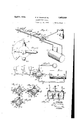
- Figure 1 is a view in perspective of an ape paratus for producing a combustible mixture adapted to be employed in connection with a plurality of gas burners, V
- Figure 2 is an enlarged fragmentary plan View of the combinedfcontrol 1 valve and mixer, a i
- Figure 3 isa plan view "of the device in section, a
- FIG. 4 is a horizontal section of the combined valve and mixer showing the valve in closed position, V
- Figure 5 is a similar section to that shown .70 in Fig. 4, withthe valvein open position
- Figure 6 is a'horizontal section similar to a that shown in Figs. 4 and 5, with the valve partially closinglcertain of the passages,
- Figure 7 isa fragmentary bottom plan-'75 view of the device shown in -Fig. -1',
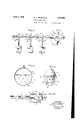
- Figure 8 isjfa transverse vertical section of the tank which contains a hydrocarbon liquid, p 5
- Figure 9 is'a view in perspective with parts brokenaway tolshow the partitions which 'causeqgas to be saturated with a hydrocarbon.
- Figure 10 isa fragmentary side view show ing thesafety control, i e f Figurell is a vertical section of a hydrocarbon'liq'uid vaporizing tank.'
- 10 designates either-a storage tank or a device for generating acetylene gas, which is connected by means of a pipe 11 with a chamber 12 of a valve casing13.
- a tank 14 has a fillingtube 15 proje'cting outwardly of the tank and also inwardly, r as shown at 16, andterminating midwaybetween the tube and bottom ofjthe tankwhen the tank is located at a horizontal position.
- A'small bent tube 17 extendsfrom' thelowe'r inner end of the pipe 15 'tothe outer-end.
- the tank may be filled shown in Fig. 1,, certain of the parts being 65 ca 18 normally closes the outer end of the tu 15.
- the inner portion is located between a pair of partitions generally designated by the numerals 20 and 21.
- a pipe 22 connects the discharge end 23 of the tank 14 with an inlet port 24 formed in the valve casing 13.
- a pipe 25 which is adapted to supply the tank with acetylene gas is connected with the inlet portion 26 of the tank and a port 27 formed in the valve casing 13.
- the partitions 20 and 21 are more particularly illustrated in Fig. 9, and in which the uppermost portion 30 is formed of metal and secured to the inner wall of the tank 14.
- the metal member depends from the inner wall for less than onehalf the height of the tank, or less than one-half of the diameter of said tank.
- the inner edge is provided with a U-shaped flange 31 adapted to receive the upper edge of a felt member 32 which is provided with a plurality of perforations 33.
- the opposite face of the felt member 32 is covered with a coarse cotton fabric 34, such as towelling or wicking which will permit the acetylene gas to pass through the same while becoming saturated with a hydrocarbon 35 located in the lower half of the tank. It will be noted by this construction, as shown in Fig.
- Valve which is semi-circular in form is rotatably mounted in the chamber 12 of the valve casing 13 and is operated by a handle 41 secured to a valve stem 42.
- One face of the valve, as shown at 43, is fiat and is disposed in a vertical plane passing through the diameter of the circular chamber 12.
- the rounded portion 44 of the valve has a cut out portion 45 which is adapted to be alined with the port 24 and a port 46 for placing the pipe in communication with a passage 47 which connects the valve chamber 12 with a mixing chamber 48.
- pipes 25 and 11 may be placed in communication with the valve chamber 12 and also with the mixing chamber 48 whereby acetylene gas may not only be supplied to the tank 14, but also to the mixing chamber.
- the mixing chamber 48 is formed in an extension 50 of the valve casing 13 and is provided with a plurality of bafiles 51 arranged in such a manner as to cause the combustible mixture to form a tortuous path through the mixing chamber, whereby the acetylene gas and the hydrocarbon charge are thoroughly mixed before they enter a supply pipe 52.
- a plate extends from the valve casing 13 and is provided with a dial 61 over which a pointer 62 moves and the dial in cooperation with the pointer determines the various positions of the valve when it operates through the handle 41.
- the supply pipe 52 may be connected with an internal combustion engine for supplying a combustible mixture to the same, or said pipe may be the means for supplying a combustible mixture to a plurality of burners 53, 54 and 55, or to a welding or cutting torch. These burners are connected to the pipe 52 by means of connection 56 and are each controlled by a valve 57 of the well known type in gas burners.
- a safety device is employed in connection with the burners to prevent said burners from being closed off entirely while leaving the valve 40 pen.
- a rod is slidably mounted in guides 71 carried by the supply pipe 52 and has a link 7O pivoted thereto.
- the link has a slotted portion 72 which receives a pin 73 located eccentrically with respect to the center 74 of the valve casing.
- Each of the stems 75 of the burner valves 57 is provided with a lug 76 adapted to engage a lug 77 on the rod 7 0 when the burners have been opened and which will prevent the burners from being closed long as the valve 40 is open.
- valve must be closed in order to permit the lug 7 7 to release lug 76 in order to permit operation of the valve 57.
- this construction as just described it will be necessary to close the control valve 40 entirely before any of the burners can be closed.
- the knob 80 connected with the rod 70 which is square in cross section and move the rod to the left while one or more burners are being closed.
- the slot 72 in the end of the rod which receives the pin 73 permits the bar to be moved far enough to the left so that the burners may be closed without necessitating actuating of the valve 40.
- the operationof the device is as follows:
- the tank 14 is placed in the ground and disposed in a horizontal position after which the tank is filled approximately one-half full, through the pipe 15.
- the acetylene generator or tank 10 is connected by means of the pipe 11 with the valve casing 13 so that when the handle 41 is moved to a posi. tion where the valve 40 opens all of the. ports, the acetylene gas will pass from'the pipe 11 through the pipe into the tank 14 and then pass through the saturated partitions thereby taking up a predetermined quantity of the hydrocarbon and carrying it through the pipe 22 and through the ports 24 and 46, and the passage 47 whence the saturated gas will enter the mixing chamber 48.
- the mixing chamber is also open to the chamber 12 of the valve casing 13 a predetermined quantity of acetylene gas will pass directly into the mixing chamber and be thoroughly mixed with the saturated gas coming through the tank 14 before it enters the supply pipe 52. It will'be noted that by the proper adjustment of the valve 40 the supply of the acetylene gas to the tank 14 and also the mim'ng chamber 48 may be varied to give the desired results.
- a valve casing provided with a port in communication with a source of acetylene gas, an outlet port in communication with the tank for supplying acetylene gas to the hydrocarbon in the tank, an inlet port in communication with the tank. for supply hydrocarbon saturated acetylene gas to the casing and a dischargevport for gases from the casing, a valve in the casing tor placing the first-mentioned port in communication withthe outlet port, for placing the first port in communication with the discharge port, or for placing the inlet port in communication with the discharge port.
- a tank containing a liquid hydrocarbon a valve casing provided with a port incommunication with a source of acetylene gas,an outlet portin communication with the tank for supplying acetylene gas to the hydrocarbon in the tank, an inlet port in communication with the tank for supplying hydrocarbon saturated acetye lene gas to the casing and a discharge port for gases fromthe casing, a valve in the casing for placing the first-mentioned port in communication with the outlet port, for placing the first port in communication with the discharge port, or for placing the inlet port in 1 communication with the discharge port, the casing having a chamber therein in communi' cation with the ports and also'having a passage connecting the chamber adjacent the inlet port with the exterior of the valve havinga pocket adapted to space an end of the passage and the inlet port while cutting oif' the discharge port.
- a tank containing, a liquid hydrocarbon, a valve casing providedwith a port in communication with a source of acetylene gas, an outlet port in communication with the tank 'for supplying,
- acetylene gas to the hydrocarbon in the tank, an inlet port in communication with the tank for supplying hydrocarbon saturated acetylene gas to the casing and adischarge port for gases from the casing, a valve in the casing for placing the first-mentioned port in communication with the outlet port, for placing the first port in communication with the dis- Signed at Arkansas City in the county of Cowley and State of Kansas, this 21 day of February, A. D. 1928.-
Landscapes
- Engineering & Computer Science (AREA)
- Chemical & Material Sciences (AREA)
- Combustion & Propulsion (AREA)
- Mechanical Engineering (AREA)
- General Engineering & Computer Science (AREA)
- Feeding And Controlling Fuel (AREA)
Description
April 5, 1932. P. E. WEBB ET AL CARBURETING DEVICE Filed Feb. 28, 1928' 2 Sheets-Sheet l INVENTORS P104 5 14 555 ATTORNEY Apr-I15; 1932.
4 RE. WEBB ET AL CARBURE'IING DEVICE Filed Feb. 28, 1928 2 Sheets-Sheet a m E W ATTORNEY Patented Apr. 5,1932 i UNITED srArEsr arent armor? PAUL n'wnisn AND'FRANK A. were, \OEARK'ANSAS CITY; KANSAS GARBURETING DEVICE Application: .fil'ed February 28, 1928; Serial No. 257,765.
portion Of the liquid in the tank above the level of the liquidgand provided with asufficientdegree of porosity to permitthe passage of gas'through the saturated material whereby thegas will absorb a predetermined quantity of the liquid when passingthrough the partition. a
Another object of the invention isthe provision of a combined control valve and mixingjcham'ber for controlling the flow of acetylene gas to a burneror supply'pipe or welding torch, and also to a tank containing a hydrocarbon liquid whereby the 1 last named portion of the acetylene gas is saturated with the hydrocarbon, after a, which the hydrocarbon saturated acetylene gas is conducted to the control valve and mixed where said saturated gas is mixed with the first mentioned portion offlacetylene gas beto an internal combustion ,engine,-or to a weldlng or cuttmgtorch.
A further-object of the invention when,
so that the source from which the acetylene gas in the mixture maybe cut off at the time the stop cook or burner valves are closed, provision being made to permit the cutting oil of one or more burners without interrupting the fiowof the colnbustible'mixture to the remaining burners,
This invention will "be best understood from a consideration ofthe following detailed description, in connection with'the to be understood that the invention "is? not fore the gases are supplied to the burner or accompanying I drawings nevertheless, it is half fullof a hydrocarbonand no more. A 100 confined to the disclosure being susceptible of such changes and modifications as shall. define no material departure from thesalient features of the invention as expressed inthe appended claims.
In the drawings Figure 1 is a view in perspective of an ape paratus for producing a combustible mixture adapted to be employed in connection with a plurality of gas burners, V
Figure 2 is an enlarged fragmentary plan View of the combinedfcontrol 1 valve and mixer, a i
Figure 3 isa plan view "of the device in section, a
Figure 4 is a horizontal section of the combined valve and mixer showing the valve in closed position, V
Figure 5 is a similar section to that shown .70 in Fig. 4, withthe valvein open position,
' Figure 6 is a'horizontal section similar to a that shown in Figs. 4 and 5, with the valve partially closinglcertain of the passages,
Figure 7 isa fragmentary bottom plan-'75 view of the device shown in -Fig. -1',
Figure 8 isjfa transverse vertical section of the tank which contains a hydrocarbon liquid, p 5
Figure 9 is'a view in perspective with parts brokenaway tolshow the partitions which 'causeqgas to be saturated with a hydrocarbon.
. Figure 10 isa fragmentary side view show ing thesafety control, i e f Figurell is a vertical section of a hydrocarbon'liq'uid vaporizing tank.'
Referring more particularlyto the drawings, 10' designates either-a storage tank or a device for generating acetylene gas, which is connected by means of a pipe 11 with a chamber 12 of a valve casing13.
A tank 14: has a fillingtube 15 proje'cting outwardly of the tank and also inwardly, r as shown at 16, andterminating midwaybetween the tube and bottom ofjthe tankwhen the tank is located at a horizontal position.
A'small bent tube 17 extendsfrom' thelowe'r inner end of the pipe 15 'tothe outer-end. By'this construction 'the tank may be filled shown in Fig. 1,, certain of the parts being 65 ca 18 normally closes the outer end of the tu 15. The inner portion is located between a pair of partitions generally designated by the numerals 20 and 21. A pipe 22 connects the discharge end 23 of the tank 14 with an inlet port 24 formed in the valve casing 13. A pipe 25 which is adapted to supply the tank with acetylene gas is connected with the inlet portion 26 of the tank and a port 27 formed in the valve casing 13.
The partitions 20 and 21 are more particularly illustrated in Fig. 9, and in which the uppermost portion 30 is formed of metal and secured to the inner wall of the tank 14. The metal member depends from the inner wall for less than onehalf the height of the tank, or less than one-half of the diameter of said tank. The inner edge is provided with a U-shaped flange 31 adapted to receive the upper edge of a felt member 32 which is provided with a plurality of perforations 33. The opposite face of the felt member 32 is covered with a coarse cotton fabric 34, such as towelling or wicking which will permit the acetylene gas to pass through the same while becoming saturated with a hydrocarbon 35 located in the lower half of the tank. It will be noted by this construction, as shown in Fig. 3, that the acetylene gas entering the portion 26 of the tank will pass through the upper portion of the coarse towelling which is saturated with hydrocarbon, pass through partition openings 33 and will then be discharged through the pipe 22. The felt 32 acts as a wick for maintaining the lower portion of the partition fairly saturated in the hydrocarbon.
Valve which is semi-circular in form is rotatably mounted in the chamber 12 of the valve casing 13 and is operated by a handle 41 secured to a valve stem 42. One face of the valve, as shown at 43, is fiat and is disposed in a vertical plane passing through the diameter of the circular chamber 12. The rounded portion 44 of the valve has a cut out portion 45 which is adapted to be alined with the port 24 and a port 46 for placing the pipe in communication with a passage 47 which connects the valve chamber 12 with a mixing chamber 48. At this time pipes 25 and 11 may be placed in communication with the valve chamber 12 and also with the mixing chamber 48 whereby acetylene gas may not only be supplied to the tank 14, but also to the mixing chamber.
The mixing chamber 48 is formed in an extension 50 of the valve casing 13 and is provided with a plurality of bafiles 51 arranged in such a manner as to cause the combustible mixture to form a tortuous path through the mixing chamber, whereby the acetylene gas and the hydrocarbon charge are thoroughly mixed before they enter a supply pipe 52.
A plate extends from the valve casing 13 and is provided with a dial 61 over which a pointer 62 moves and the dial in cooperation with the pointer determines the various positions of the valve when it operates through the handle 41.
The supply pipe 52 may be connected with an internal combustion engine for supplying a combustible mixture to the same, or said pipe may be the means for supplying a combustible mixture to a plurality of burners 53, 54 and 55, or to a welding or cutting torch. These burners are connected to the pipe 52 by means of connection 56 and are each controlled by a valve 57 of the well known type in gas burners.
When used with a stove, provision is made for preventing closing of the valve 57 while the valve 40 is open, and while the last mentioned valve permits acetylene gas to be conducted to the tank 26 and also the mixing chamber 40, while permitting the saturated gas to be conducted to the mixing chamber. This precaution is taken because of the fact that the acetylene gas will be charged into the tank 14 which is undesirable when the gas stove is not bein employed. Furthermore, the tank 14 is fiuried at a predetermined depth in order to maintain the contents of said tank at a temperature which will prevent too great an expansion of the fluids in said tank. However, in those regions where the temperature is normally high and it is not possible to bury the tank 14 at a sufiicient depth below the surface to maintain the proper temperature of said tank, a safety device is employed in connection with the burners to prevent said burners from being closed off entirely while leaving the valve 40 pen.
A rod is slidably mounted in guides 71 carried by the supply pipe 52 and has a link 7O pivoted thereto. The link has a slotted portion 72 which receives a pin 73 located eccentrically with respect to the center 74 of the valve casing. Each of the stems 75 of the burner valves 57 is provided with a lug 76 adapted to engage a lug 77 on the rod 7 0 when the burners have been opened and which will prevent the burners from being closed long as the valve 40 is open.
It will be noted that the valve must be closed in order to permit the lug 7 7 to release lug 76 in order to permit operation of the valve 57. By this construction as just described it will be necessary to close the control valve 40 entirely before any of the burners can be closed. However, where a number of burners have been lighted and it is desired to out off some of the burners while not disturbing adjustment of the control valve, it is only necessary to grasp the knob 80 connected with the rod 70 which is square in cross section and move the rod to the left while one or more burners are being closed. The slot 72 in the end of the rod which receives the pin 73 permits the bar to be moved far enough to the left so that the burners may be closed without necessitating actuating of the valve 40.
The operationof the device is as follows:
The tank 14 is placed in the ground and disposed in a horizontal position after which the tank is filled approximately one-half full, through the pipe 15. The acetylene generator or tank 10 is connected by means of the pipe 11 with the valve casing 13 so that when the handle 41 is moved to a posi. tion where the valve 40 opens all of the. ports, the acetylene gas will pass from'the pipe 11 through the pipe into the tank 14 and then pass through the saturated partitions thereby taking up a predetermined quantity of the hydrocarbon and carrying it through the pipe 22 and through the ports 24 and 46, and the passage 47 whence the saturated gas will enter the mixing chamber 48. Since the mixing chamber is also open to the chamber 12 of the valve casing 13, a predetermined quantity of acetylene gas will pass directly into the mixing chamber and be thoroughly mixed with the saturated gas coming through the tank 14 before it enters the supply pipe 52. It will'be noted that by the proper adjustment of the valve 40 the supply of the acetylene gas to the tank 14 and also the mim'ng chamber 48 may be varied to give the desired results.
2. In a carbureting device, a tank containing a liquid hydrocarbon, a valve casing provided with a port incommunication with a source of acetylene gas,an outlet portin communication with the tank for supplying acetylene gas to the hydrocarbon in the tank, an inlet port in communication with the tank for supplying hydrocarbon saturated acetye lene gas to the casing and a discharge port for gases fromthe casing, a valve in the casing for placing the first-mentioned port in communication with the outlet port, for placing the first port in communication with the discharge port, or for placing the inlet port in 1 communication with the discharge port, the casing having a chamber therein in communi' cation with the ports and also'having a passage connecting the chamber adjacent the inlet port with the exterior of the valve havinga pocket adapted to space an end of the passage and the inlet port while cutting oif' the discharge port.
3. In a carbureting device, a tank containing, a liquid hydrocarbon, a valve casing providedwith a port in communication with a source of acetylene gas, an outlet port in communication with the tank 'for supplying,
acetylene gas to the hydrocarbon in the tank, an inlet port in communication with the tank for supplying hydrocarbon saturated acetylene gas to the casing and adischarge port for gases from the casing, a valve in the casing for placing the first-mentioned port in communication with the outlet port, for placing the first port in communication with the dis- Signed at Arkansas City in the county of Cowley and State of Kansas, this 21 day of February, A. D. 1928.-
PAUL E. WEBB. FRANK A. WEBB;
Priority Applications (1)
| Application Number | Priority Date | Filing Date | Title |
|---|---|---|---|
| US257765A US1852909A (en) | 1928-02-28 | 1928-02-28 | Carbureting device |
Applications Claiming Priority (1)
| Application Number | Priority Date | Filing Date | Title |
|---|---|---|---|
| US257765A US1852909A (en) | 1928-02-28 | 1928-02-28 | Carbureting device |
Publications (1)
| Publication Number | Publication Date |
|---|---|
| US1852909A true US1852909A (en) | 1932-04-05 |
Family
ID=22977654
Family Applications (1)
| Application Number | Title | Priority Date | Filing Date |
|---|---|---|---|
| US257765A Expired - Lifetime US1852909A (en) | 1928-02-28 | 1928-02-28 | Carbureting device |
Country Status (1)
| Country | Link |
|---|---|
| US (1) | US1852909A (en) |
-
1928
- 1928-02-28 US US257765A patent/US1852909A/en not_active Expired - Lifetime
Similar Documents
| Publication | Publication Date | Title |
|---|---|---|
| US1852909A (en) | Carbureting device | |
| US3485567A (en) | Liquid fuel burning appliance and components therefor | |
| US2705872A (en) | Vaporizing apparatus | |
| US1719397A (en) | Fuel-feeding system for furnaces | |
| US1701881A (en) | Camp stove | |
| US1718473A (en) | Oil-burning device | |
| US2434346A (en) | Generator burner and fuel control therefor | |
| US2067666A (en) | Liquid fuel burner | |
| US2368356A (en) | Oil burner | |
| US1614854A (en) | Hydrocarbon stove and burner therefor | |
| US422317A (en) | Petroleum-burner for stoves | |
| US2475024A (en) | Semicylindrical pot-type burner | |
| US1613060A (en) | Hydrocarbon burner | |
| US2669847A (en) | Method and apparatus for vaporizing and distributing hydrocarbon fuels | |
| US1743081A (en) | Oil-burning apparatus | |
| US2397529A (en) | Burner for army type stoves | |
| US1052635A (en) | Vaporizer and burner. | |
| US1234530A (en) | Carbureter. | |
| US1567288A (en) | Burner | |
| US1348964A (en) | Vapor-stove | |
| US1650065A (en) | Liquid-fuel burner | |
| US1511420A (en) | Oil stove | |
| US1641728A (en) | Manifold heater for internal-combustion engines | |
| US738779A (en) | Burner. | |
| US1522629A (en) | Vapor-generating burner |