US1852901A - Bathtub adjustable leg - Google Patents
Bathtub adjustable leg Download PDFInfo
- Publication number
- US1852901A US1852901A US521262A US52126231A US1852901A US 1852901 A US1852901 A US 1852901A US 521262 A US521262 A US 521262A US 52126231 A US52126231 A US 52126231A US 1852901 A US1852901 A US 1852901A
- Authority
- US
- United States
- Prior art keywords
- leg
- wedge
- tongue
- received
- tub
- Prior art date
- Legal status (The legal status is an assumption and is not a legal conclusion. Google has not performed a legal analysis and makes no representation as to the accuracy of the status listed.)
- Expired - Lifetime
Links
Images
Classifications
-
- A—HUMAN NECESSITIES
- A47—FURNITURE; DOMESTIC ARTICLES OR APPLIANCES; COFFEE MILLS; SPICE MILLS; SUCTION CLEANERS IN GENERAL
- A47K—SANITARY EQUIPMENT; ACCESSORIES THEREFOR, e.g. TOILET ACCESSORIES
- A47K3/00—Baths; Showers; Appurtenances therefor
- A47K3/16—Devices for fastening baths to floors or walls; Adjustable bath feet ; Lining panels or attachments therefor
- A47K3/162—Collapsible stands or supports for baths
Definitions
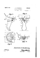
- Figure 1 is aiside elevation of a; leg attached to a bathtub in accordance with this invention, the tub being in section.
- Figure 2x isa*vi ew looking, toward the inner face of the leg.
- Figure 3 is ase'ctional view-approximately on the line 3+3 of Figure 1.
- Figure 4 is a detailsectional- View approximately on the line 4+4! of Figure 2;
- FIG. 1 Figure 5 is a detail inverted planview of the portion of thebath tubprovided with the lugs and the improved wedge.
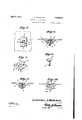
- Figure 6 is a sectional view approximately on the line 6-6 of Figure 3.
- Figure 7 is a perspective view of the wedge block.
- Figure 8 is a similar view of the bolt employed.
- Figure 9 is a sectional view approximately similar to Figure 6 but illustrating a slight modification.
- Figure 10 is a similar view illustrating a still further modification
- legs are formed with tongues to be received in the grooves.
- the flat bottom 1 of a bath tub has its edges curved at thejuncture of the sides thereof, the said curved portion being indicated in the drawings by the muneral 2.
- the under face a of the bath tub 1, adjacent to thecorners thereof, is cast with the usual depending spaced lugs 3, and the inner faces of these lugs are pointed to provide a wedge groove therebetween.
- the leg ,4 for the bath tub has its upper and open end struck at a curvature to correspond with the curved portion 2 of the tub 1; as indicated in the drawings by the numeral 51 This end e-provides a bearing for the leg l.
- Below the curved bearing edge of the leg the same is cast with the usual tongue 6, the said tonguehaving its side walls" I tapered and provided, from its outer end, with a centraldongitudinal notch '7.
- I provide a wedge block 8 designed to be received in the wedge groove afforded by the lugs 3'.
- the body of the wedgeblock is centrallyformed with a depending rib 9 of a size to be snugly received in andto' contact with the sidewalls afforded bythe 110150117.
- the rib"9 is-formed with a depending threadedstem 10on which is screwed a nut 11 that bridges the notch 7 and the tongue 6 and frictionally contacts I adjusted position so that the leg will properly rest on the floor surface and will properly engage with the curved side 2 of the tub 1 when the rib 9 of the wedge block is wholly or partly received in the notch 7 of the tongue 6.
- the bolt 10 is separable from the lug- 3, the said bolt having a tapered head 12 that is received in a tapered socket or depression 13 in the wedge block, and the rib 9 is centrally cut-away and has its confronting faces inclined outwardly, as indicated by the numerals 14 in the drawings.
- This insures a free passage of the bolt through the confronting faces of the rib of the wedge and likewise affords a freer passage of the walls afforded by the notch 7 between the sides of the rib 9.
- the wedge block 19 is inserted in the wedge g100 ⁇ 6 afforded by the lugs on the bath tub and is provided with a depending rib 21 that has a transverse slot or opening 22 therethrough for the passage of a nail or like tapered element 23.
- the wedge block also contacts with the compressible washer 24 that is arranged in the wedge groove.
Landscapes
- Health & Medical Sciences (AREA)
- Public Health (AREA)
- Epidemiology (AREA)
- General Health & Medical Sciences (AREA)
- Joining Of Building Structures In Genera (AREA)
Description
April 5, 1932 Y A. ROCKELEIN V 1,852,901 BATHTUB ADJUSTABLE LEG Fi led March 9, 1931 2 Sheets-Sheet l laureizccflJFockeZez'iz,
ATTORNEYS BATHTUB ADJUSTABLE LEG Filed March 9, 1931 2 Sheets-Sheet 2 ATTORNEYS Patented Apr. 5,' 1932,
E FicEI LAUBENCE'A. ROGKELEIN,-OF PORT JER-VIS, NEW-YORK BATHTUB ADJUSTABLE LEG- Application filed March 9,
' 19 in connection with the accompanying drawings which form part ofthe application with the un'derstanding, however, that the nnprovement is capable of extended apphca tionand is not confinedto the exact showing t of the drawings nor to the precise construction described and, therefore, such changes andimodifications may be made therefrom as do-not affect the spirit of the invention nor exceed the scope thereof as expressed in the appended claims. 7
In the drawings: t
Figure 1 is aiside elevation of a; leg attached to a bathtub in accordance with this invention, the tub being in section.
Figure 2xisa*vi ew looking, toward the inner face of the leg.
Figure 3=is ase'ctional view-approximately on the line 3+3 of Figure 1.' t V Figure 4 is a detailsectional- View approximately on the line 4+4! of Figure 2;,
1 Figure 5 is a detail inverted planview of the portion of thebath tubprovided with the lugs and the improved wedge.
, Figure 6 is a sectional view approximately on the line 6-6 of Figure 3.
Figure 7 is a perspective view of the wedge block.
Figure 8 is a similar view of the bolt employed.
Figure 9 is a sectional view approximately similar toFigure 6 but illustrating a slight modification.
Figure 10 is a similar view illustrating a still further modification;
Ordinarily bathtubs and like vessels are formed, on their under face, with spaced lugs adjacent to their corners, the confronting walls of the lugs beinginclined to form a dove-tailed groove therebetween and the 1931. Serial No. 521362..
legs are formed with tongues to be received in the grooves.
Owing tounavoidable variations inthe thickness of the, tongues and grooves a projecting shoulder is frequently left at the joint. between the leg and tub and it is very difiicult to bring the leg and'tub flush with each other, especiallywl en force,-such as a blow'of a hammeris exerted on the leg which is usually procelain coated, and such coating is liable to crack under the strain: With the ordinary'construction it is not practical and possible to build a tub in a-neat, smooth and continuousfinish at the juncture of the leg and tub and it is the object of this invention toovercome the above recited objections.
The flat bottom 1 of a bath tub has its edges curved at thejuncture of the sides thereof, the said curved portion being indicated in the drawings by the muneral 2. The under face a of the bath tub 1, adjacent to thecorners thereof, is cast with the usual depending spaced lugs 3, and the inner faces of these lugs are pointed to provide a wedge groove therebetween. The leg ,4 for the bath tub has its upper and open end struck at a curvature to correspond with the curved portion 2 of the tub 1; as indicated in the drawings by the numeral 51 This end e-provides a bearing for the leg l. Below the curved bearing edge of the leg, the same is cast with the usual tongue 6, the said tonguehaving its side walls" I tapered and provided, from its outer end, with a centraldongitudinal notch '7. The
tongueis ordinarily received in the Wedge groove provided between the lugs 3.
In carrying out'my invention I provide a wedge block 8 designed to be received in the wedge groove afforded by the lugs 3'. The body of the wedgeblock is centrallyformed with a depending rib 9 of a size to be snugly received in andto' contact with the sidewalls afforded bythe 110150117. The rib"9 is-formed with a depending threadedstem 10on which is screwed a nut 11 that bridges the notch 7 and the tongue 6 and frictionally contacts I adjusted position so that the leg will properly rest on the floor surface and will properly engage with the curved side 2 of the tub 1 when the rib 9 of the wedge block is wholly or partly received in the notch 7 of the tongue 6.
Preferably, and as disclosed by the drawings the bolt 10 is separable from the lug- 3, the said bolt having a tapered head 12 that is received in a tapered socket or depression 13 in the wedge block, and the rib 9 is centrally cut-away and has its confronting faces inclined outwardly, as indicated by the numerals 14 in the drawings. This insures a free passage of the bolt through the confronting faces of the rib of the wedge and likewise affords a freer passage of the walls afforded by the notch 7 between the sides of the rib 9.
In Figure 9 the wedge block 15 is received in the wedge opening between the lugs 16 of the bath tub and is engaged by a compressible washer 17. The wedge is held in the wedge groove by a headed bolt 18 which is screwed in the under face of the wedge.
In Figure 10 the wedge block 19 is inserted in the wedge g100\6 afforded by the lugs on the bath tub and is provided with a depending rib 21 that has a transverse slot or opening 22 therethrough for the passage of a nail or like tapered element 23. In this instance the wedge block also contacts with the compressible washer 24 that is arranged in the wedge groove.
It is thought the foregoing description when read in connection with the accompanying drawings will fully and clearly set forth the construction and advantages of the improvement to those skilled in the art to which such invention relates so that further detailed description will not be required.
My improvement it is to be understood is not necessarily restricted to use in connection with bath tubs, but the same may be employed as leg supports for other articles.
- Also the constructions disclosed by Figures 7 and 8 of the drawings may be made of a sin le piece if desired or found necessary.
aving described the invention, I claim:
1. A means for adjustably connecting a leg to a bath tub in which the tub is provided with spaced depending lugs affording a wedge groove therebetween and the leg has a projecting tongue having flared sides which are normally received in the wedge groove a and which tongue, from its outer end, is centrally formed with a longitudinal slot, said means comprising a wedge block inserted in the wedge groove, and having an element depending therefrom to be received in the slot of the tongue of the leg.
2. A means for adjustably connecting a leg to a bath tub in which the tub is provided with spaced depending lugs affording awedge oove therebetween and the leg has a projecting tongue having flared sides which are normally received in the wedge groove and which tongue, from its outer end, is centrally formed with a longitudinal slot, said means comprising a wedge block inserted in the wedge groove, and having an element depending therefrom to be received in the slot of the tongue of the le and means carried by the wedge block, adjust-able thereon and designed to frictionally contact with the under face of the tongue.
3. A means for adjustably connecting a leg to a bath tub in which the tub is provided with spaced depending lugs affording a wedge groove therebetween and the leg has a projecting tongue having flared sides which are normally received in the wedge groove and which tongue from its outer end, is centrally formed with a longitudinal slot, said means comprising a wedge block to be received in the wedge groove, a rib projecting from the wedge block to be received in the slot of the tongue, and a bolt member carried by the wedge block and having a nut screwed thereonbfor contacting with the under face of the tu 4. A means for adjustably connecting a leg to a bath tub in which the tub is provided with spaced depending lugs affording a wedge oove therebetween and the leg has a projecting tongue having flared sides which are normally received in the wedge groove and which tongue, from its outer end is centrally formed with a longitudinal slot, said means comprising a wedge block to be received in the wedge groove, a rib on the under face of the wedge block received in the slot of the tongue, said rib comprising two confronting members whose faces are inclined in opposite directions and the wedge block having a tapered opening therein, a bolt having a tapered head to be received in the opening and having its shank passing between the rib sections and said bolt being engaged by a nut which frictionally contacts with the under face of the tongue.
In testimony whereof I affix my signature.
LAURENCE A. ROCKELEIN.
Priority Applications (1)
| Application Number | Priority Date | Filing Date | Title |
|---|---|---|---|
| US521262A US1852901A (en) | 1931-03-09 | 1931-03-09 | Bathtub adjustable leg |
Applications Claiming Priority (1)
| Application Number | Priority Date | Filing Date | Title |
|---|---|---|---|
| US521262A US1852901A (en) | 1931-03-09 | 1931-03-09 | Bathtub adjustable leg |
Publications (1)
| Publication Number | Publication Date |
|---|---|
| US1852901A true US1852901A (en) | 1932-04-05 |
Family
ID=24076047
Family Applications (1)
| Application Number | Title | Priority Date | Filing Date |
|---|---|---|---|
| US521262A Expired - Lifetime US1852901A (en) | 1931-03-09 | 1931-03-09 | Bathtub adjustable leg |
Country Status (1)
| Country | Link |
|---|---|
| US (1) | US1852901A (en) |
Cited By (2)
| Publication number | Priority date | Publication date | Assignee | Title |
|---|---|---|---|---|
| US2725578A (en) * | 1952-03-28 | 1955-12-06 | Keller-Erne Lina | Transporting devices for invalids for use in bathtubs and like receptacles |
| US3151634A (en) * | 1963-05-02 | 1964-10-06 | Steel Heddle Mfg Co | Loom harness |
-
1931
- 1931-03-09 US US521262A patent/US1852901A/en not_active Expired - Lifetime
Cited By (2)
| Publication number | Priority date | Publication date | Assignee | Title |
|---|---|---|---|---|
| US2725578A (en) * | 1952-03-28 | 1955-12-06 | Keller-Erne Lina | Transporting devices for invalids for use in bathtubs and like receptacles |
| US3151634A (en) * | 1963-05-02 | 1964-10-06 | Steel Heddle Mfg Co | Loom harness |
Similar Documents
| Publication | Publication Date | Title |
|---|---|---|
| TW202018162A (en) | Building systemic board assembly and oblique lock type engagement holder that includes at least two plates, an oblique lock type engagement holder, and a screw | |
| US1852901A (en) | Bathtub adjustable leg | |
| US2079739A (en) | Bathtub | |
| US1934746A (en) | Leg mounting for furniture | |
| US1168643A (en) | Trowel. | |
| US847824A (en) | Gage. | |
| US1535928A (en) | Drain table | |
| US539197A (en) | Basin-clam p | |
| US2666966A (en) | Rung lock | |
| US1567653A (en) | Nut lock | |
| US1479243A (en) | Friction-grip hanger | |
| US1804898A (en) | False tooth | |
| US1593451A (en) | Bed-rail lock | |
| US1792974A (en) | Bolt anchor | |
| US1835587A (en) | Combined plaster terminal and molding | |
| US1594197A (en) | Hanger for insulator chains and the like | |
| US757974A (en) | Leg-fastening for bath-tubs, &c. | |
| US1285062A (en) | Bath-tub leg. | |
| US1427958A (en) | Furniture fixture | |
| GB995428A (en) | Improvements in or relating to joints | |
| US682460A (en) | Leg-fastener. | |
| USD101047S (en) | Design for a combination bathroom | |
| GB336757A (en) | Improvements in and relating to joints | |
| JPS6319608U (en) | ||
| MA53200B1 (en) | One piece shower head |