US1852744A - Corner pocket mounting device - Google Patents
Corner pocket mounting device Download PDFInfo
- Publication number
- US1852744A US1852744A US568287A US56828731A US1852744A US 1852744 A US1852744 A US 1852744A US 568287 A US568287 A US 568287A US 56828731 A US56828731 A US 56828731A US 1852744 A US1852744 A US 1852744A
- Authority
- US
- United States
- Prior art keywords
- corner
- area
- edges
- card
- picture
- Prior art date
- Legal status (The legal status is an assumption and is not a legal conclusion. Google has not performed a legal analysis and makes no representation as to the accuracy of the status listed.)
- Expired - Lifetime
Links
- 239000000463 material Substances 0.000 description 41
- 239000012780 transparent material Substances 0.000 description 20
- 239000000853 adhesive Substances 0.000 description 9
- 230000001070 adhesive effect Effects 0.000 description 9
- 238000003780 insertion Methods 0.000 description 9
- 230000037431 insertion Effects 0.000 description 9
- 238000004519 manufacturing process Methods 0.000 description 2
- 229920000298 Cellophane Polymers 0.000 description 1
- 229920002160 Celluloid Polymers 0.000 description 1
- 238000000034 method Methods 0.000 description 1
Images
Classifications
-
- B—PERFORMING OPERATIONS; TRANSPORTING
- B42—BOOKBINDING; ALBUMS; FILES; SPECIAL PRINTED MATTER
- B42F—SHEETS TEMPORARILY ATTACHED TOGETHER; FILING APPLIANCES; FILE CARDS; INDEXING
- B42F5/00—Sheets and objects temporarily attached together; Means therefor; Albums
- B42F5/06—Corner-holding devices, e.g. for photographs
Definitions
- the purpose of this invention is to provide an improved device in the nature of a pocket for securing photographs, pictures, cards and the like to any suitable mounting in a convenient, artistic manner, by affixing to the mount several of these pocket devices in position to register with the corners of the card or picture, and inserting the corners of the picture in the respective pockets.
- Another object is to provide a pocket of this character which shall be transparent and therefore substantially invisible, so that it shall not ob struct or cover any portion of the picture which it overlies.
- a further object is to adapt a pocket of this character for securing the card or picture either temporarily and removable, or permanently at the option of the user.
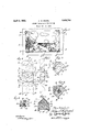
- Figure 1 is a plan view showing a picture as it appears when secured to a mount by devices embodying this invention.
- Figure 2 is a plan view showing the blank of transparent material employed in the manufacture of the device, and indicating how such blanks may be cut from a continuous strip.
- Figure 3 is a plan view of the blank after the folding. operation.
- Figure 4 is a plan view of the blank showing the same mounted upon its paper backing ready for use, and constituting a completed mounting device in accordance with this invention.
- Figure 5 is a plan view of the device viewed from the under side, showing the gummed surface of the paper backing.
- Figure 6 is a plan view of the face side of a modified form of pocket mounting device embodying this invention.
- Figure 7 is a planview showing the blank of transparent material employed for the manufacture of such modified form.
- 1 indicates a picture to be mounted, and a. suitable background sheet or mount is shown fragmentarily at 2.
- the picture, 1, is
- corner devices therefore extend under the overlying areas of the corner pocket fittings or mounting devices shown at 3.
- This view also represents in dotted outline the portion of each corner pocket fitting which extends under the picture for securement to the mount, 2.
- Each of the pocket fittings consists of a portion made of transparent material, such as thin celluloid or cellophane, and an opaque backing member which serves several purposes, as will presently appear.
- the transparent material may be formed substantially in accordance with the method outlined in my Patent No. 1,799,221, dated April 7, 1931, for making corner pockets of opaque material, such as paper. That is, the blanks of transparent material may be cut from a continuous strip, as indicated in Figure 2, each blank being shaped as shown in full lines, with similar consecutive blanks, as indicated in dotted lines.
- Each blank includes a transverse slit, 4, which is preferably, though not necessarily, angular, with the apex, 5, of the angle at the center line of the strip.
- the ends of the slit lie respectively in a pair of creases or lines of fold indicated in the blank at 6, 6, extending at right angles to each other, and each substantially at 45 degrees to the center line and to the lateral margins of the strip.
- the corners of the blank are cut oil at diagonal lines, 7 7, parallel to the dotted lines, 6, 6, while the end of the blank is defined by a transverse line, 8, connecting these oblique lines.
- the material between the lines, 6, 6, and 7, 7, constitutes a pair of tabs or flaps, 9, which are folded back under the remaining area of the blank, as indicated in Figure 3.
- the outline of the opposite end of the blank is that which results from cutting another and similar blank with diagonal corner outlines, 7, 7, and the transverse edge, 8, so that this opposite end of the blank includes triangular tabs, 10, at each corner, projecting beyond the middle portion of the margin at 11.
- the transparent fitting thus produced is intended to be applied to the corner of a card or picture by inserting the corner of the picture through the slit, 4, until its edges stop at the folds at line 7, 7, with the tabs, 9, extending under the picture, and with the area adj ac-ent the end, 11, also underlying the picture or card.
- the transparent material may be folded closely enough so that the corner fittings will be held frictionally in place when applied to the corners of a card or picture, and by thus placing them and moistening the under surface of the backing material the picture may be positioned, as desired, on the mount, 2, and the corner fittings may be pressed down for permanent securement thereto. This will leave the picture removably held by the corner fittings, but if it is to be permanently secured the exposed gummed areas at 14 may be utilized, as already described, when the fittings are originally placed on the picture; or, aft-er they have been secured to the mount, the picture may be temporarily removed while these areas are moistened, so that when it is replaced it may be pressed firmly down over said areas and thus permanently fastened.
- Figure 6 illustrates a somewhat simpler design of corner pocket in which the transparent material comprises a triangular area, 20, intended to overlie the corner of the card or icture which it holds, while flaps, 21, are folded back at the lines, 22, so as to extend under the card or picture.
- the lines of fold, 22, 22, extend at right angles to each other, forming the corner of the pocket, while the third edge, 23, of the triangular area, 20, is diagonally disposed, preferably at 45 degrees to each of the fold lines, 22.
- Each of the flaps, 21, is also in the form of a triangle, one of whose edges is the line of fold at 22, while its adjacent edge, 24, is equal in length to said edge, 22.
- the third side of this triangle, 25, is equal in length to the side, 23, of the area, 20, and these edges, 25, of the two triangular flaps, 21, abut each other when the flaps are folded under the area, 20, as illustrated in Figure 6.
- the pocket is completed by securing to the under faces of the flaps, 21, a square of gummed paper or the like which is treated with adhesive on both its under and upper surface, so that the exposed under surface is adapted for securement of the pocket to a card or mount like that shown in Figure 1.
- the transparent material for the corner pocket shown in Figure 6 may be quite simply cut from a continuous strip or ribbon, as indicated in Figure 7, each blank consisting of the triangular area, 20, and the two asso ciated triangles, 21, previously termed flaps.
- the blanking die which cuts this trapezoidal piece from the strip may include means for impressing or scoring in the piece the lines of fold, 22, 22, or the material may be handled by automatic machinery for completing these folds, and also for applying the gummed backing sheet thereto.
- a corner pocket of transparent sheet material combined with a backing sheet said transparent material comprising an area having two adjacent edges at right angles with flaps of the material folded under said area adjacent said edges and secured to the backing sheet; said area having a slit disposed diagonally with respect to said edges to receive the corner of a picture card or the like, and the backing sheet being gummed on its under side for securement to a mount.
- a corner pocket of transparent sheet material combined with a backing sheet said transparent material comprising an area having two adjacent edges at right angles with continuous portions of the material folded under said area adj aeent said edges, the said area having a slit disposed diagonally with respect to said edges to receive the corner of a picture card or the like, so that the corner portion of said card underlies said area of the transparent material adjacent the fold-- ed edges and overlies the remainder of said area, the backing sheet being gummed on both surfaces, whereby its upper surface is secured to the transparent material and its under surface is adapted for securement to a mount,
- the aforesaid portion of the transparent material which underlies the card being apertured to expose the upper gummed surface of the backing sheet to permit adhesive securement thereof to the back of the card.
- a corner pocket of transparent sheet material comprising an area having two adjacent edges at right angles, with portions of said material folded under said area adj acent said edges, said area having a slit disposed diagonally with respect to said edges to permit the insertion of the corner of a picture card or the like, with the corner portion underlying the transparent material adj acent the folded edges and overlying the remainder of said area, said area being apertured, and the transparent corner pocket being adhesively secured to sheet material gummed on its upper surface, whereby a portion of said gummed surface is exposed through such aperture for securement directly to the card.
- a corner pocket of transparent sheet material comprisin an area having two adjacent edges at right angles, with flaps of the material folded under said area adjacent said edges, said area having a slit disposed diagonally with respect to said edges to permit insertion of the corner of a picture card or the like, so that said corner lies under the transparent material adjacent the folded edges thereof, and overlies said material at the other side of the slit, the flaps being dimensioned to completely underlie the area bounded by the slit and the folded edges of the pocket to form a smooth surface for the reception of the corner of the card.
- a corner pocket of transparent sheet material comprising an area having two adjacent edges at right angles, with flaps of the material folded under said area adjacent said edges, said area having a slit disposed diagonally with respect to said edges to permit insertion of the corner of a picture card or the like, so that said corner lies under the transparent material adjacent the folded edges thereof, and overlies said material at the other side of the slit, the flaps being dimensioned to extend from said folded edges beyond the diagonal slit and to lap under the area of the material whi ch the card overlies.
- a corner pocket mounting device composed of a piece of transparent sheet material having two adjacent edges at right angles along which the material is folded upon itseif providing space for the insertion of the corner of a picture card or the like with its adj acent edges stopped by said folds, and with a portion of the transparent material overlying the face of the card, together with a single backing sheet of paper or the like gummed on both sides for adhesive securement respectively to the transparent material and to a mount.
- hypotenuse and a backing sheet of paper:
- a corner pocket of transparent sheet material having two edges at right angles with flaps of the material folded under the" area adjacent said edges, and a backing sheet of paper or the like gummed-on both sides with said flaps adhesively secured to one side of said backing sheet, the other side being adapted for securement to a mount.
- 'A corner pocket mounting device composed of a piece of transparent sheet material having two adjacent edges at right angles along which the material is folded upon itself, providing space for the insertion of the corner of a picture card or the like with its adjacent edges stopped by said folds, and with an unbroken triangular portion of the transparent material overlying the face of the card, the two folded edges constituting two sides of said triangle, and the card being introduced by insertion under the third side, the material which is folded under said triangle extending beyond said third side and lying under the card, and means for securing said underlying portion of the material to a mount.
- a corner pocket composed of sheet material and comprising a right-angle-triangular area with flaps folded thereunder along the legs of the triangle and projecting beyond the hypotenuse, and a backing sheet gummed on both sides having one side adhesively secured to the flaps, leaving its opposite side exposed for adhesive securement to a mount.
- a corner pocket of sheet material having two edges at right angles with flaps of the material folded under said area adjacent said edges, and a backing sheet gummed on both sides with said flaps adhesively secured to one side of said sheet, the other side being exposed for securement to a mount.
- a corner pocket of sheet material comprising an area having two adjacent edges at right angles with flaps of the material folded under said area adjacent said edges, the said area having a slit disposed diagonally with respect to said edges to permit insertion of the corner of a picture card or the like so that said corner lies under said sheet material adjacent the folded edges thereof and overlies said material at the other side of the slit, the flaps being dimensioned to completely underlie the area bounded by the slit and the folded edges of the pocket to form a smooth surface for reception of said corner of the card.
- a corner pocket mounting device composed of a piece of sheet material having two adjacent edges at right angles along which the material is folded upon itself, providing space for the insertion of the'corner'of a' picture card'or the like with its adjacent edges stopped by saidfolds, and with a portion .of. said sheet material overlying the face of the card, together with a single backing'sheet'of paper or the like gummed "on both sides for adhesive secure-ment re- 1tspectively to the saidsheet' material and to a mount.
Description
April 5, 1932.
A. W. ENGEL CORNER POCKET MOUNTING DEVICE Filed Oct. 12, 1931 Patented Apr. 5, 1932 PATENT OFFICE ALBERT W. ENGEL, OF CHICAGO, ILLINOIS CORNER POCKET MOUNTING DEVICE Application filed October 12, 193-1. Serial No. 568,387.
The purpose of this invention is to provide an improved device in the nature of a pocket for securing photographs, pictures, cards and the like to any suitable mounting in a convenient, artistic manner, by affixing to the mount several of these pocket devices in position to register with the corners of the card or picture, and inserting the corners of the picture in the respective pockets. Another object is to provide a pocket of this character which shall be transparent and therefore substantially invisible, so that it shall not ob struct or cover any portion of the picture which it overlies. A further object is to adapt a pocket of this character for securing the card or picture either temporarily and removable, or permanently at the option of the user.
In the drawings:
Figure 1 is a plan view showing a picture as it appears when secured to a mount by devices embodying this invention.
Figure 2 is a plan view showing the blank of transparent material employed in the manufacture of the device, and indicating how such blanks may be cut from a continuous strip.
Figure 3 is a plan view of the blank after the folding. operation.
Figure 4 is a plan view of the blank showing the same mounted upon its paper backing ready for use, and constituting a completed mounting device in accordance with this invention.
Figure 5 is a plan view of the device viewed from the under side, showing the gummed surface of the paper backing.
Figure 6 is a plan view of the face side of a modified form of pocket mounting device embodying this invention.
Figure 7 is a planview showing the blank of transparent material employed for the manufacture of such modified form.
In the drawings, 1 indicates a picture to be mounted, and a. suitable background sheet or mount is shown fragmentarily at 2. To emphasize the special advantage of the use of transparent material in my improved corner pocket mounting devices, the picture, 1, is
represented as having no marginal area, and
the corner devices therefore extend under the overlying areas of the corner pocket fittings or mounting devices shown at 3. This view also represents in dotted outline the portion of each corner pocket fitting which extends under the picture for securement to the mount, 2.
Each of the pocket fittings consists of a portion made of transparent material, such as thin celluloid or cellophane, and an opaque backing member which serves several purposes, as will presently appear. The transparent material may be formed substantially in accordance with the method outlined in my Patent No. 1,799,221, dated April 7, 1931, for making corner pockets of opaque material, such as paper. That is, the blanks of transparent material may be cut from a continuous strip, as indicated in Figure 2, each blank being shaped as shown in full lines, with similar consecutive blanks, as indicated in dotted lines.
Each blank includes a transverse slit, 4, which is preferably, though not necessarily, angular, with the apex, 5, of the angle at the center line of the strip. The ends of the slit lie respectively in a pair of creases or lines of fold indicated in the blank at 6, 6, extending at right angles to each other, and each substantially at 45 degrees to the center line and to the lateral margins of the strip. The corners of the blank are cut oil at diagonal lines, 7 7, parallel to the dotted lines, 6, 6, while the end of the blank is defined by a transverse line, 8, connecting these oblique lines. The material between the lines, 6, 6, and 7, 7, constitutes a pair of tabs or flaps, 9, which are folded back under the remaining area of the blank, as indicated in Figure 3. The outline of the opposite end of the blank is that which results from cutting another and similar blank with diagonal corner outlines, 7, 7, and the transverse edge, 8, so that this opposite end of the blank includes triangular tabs, 10, at each corner, projecting beyond the middle portion of the margin at 11.
The transparent fitting thus produced, as illustrated in Figure 3, is intended to be applied to the corner of a card or picture by inserting the corner of the picture through the slit, 4, until its edges stop at the folds at line 7, 7, with the tabs, 9, extending under the picture, and with the area adj ac-ent the end, 11, also underlying the picture or card. This leaves only the portion between the lines of fold, 7, '7, and the slit, 4, exposed at the upper side of the picture and overlying the latter, as shown in Figure 1. However, to facilitate the securement of the fitting to the mount, 2, and also to hold the tabs, 9, in their folded position, I prefer to add to the fitting a backin g of sheet material gummed on both surfaces and cut to conform to the outline of the fitting as it appears in Figure 3. The adhesive material on the upper surface of this blank, 12, secures it permanently to the under face of the tabs, 9, and to the nut er surface of the remaining area of the j The adhesive on the opposite face (the under side) of the blank, 12, is available for securing it in place on the mount, 2. And by forming the transparent blank witl an aperture, 13, in the area between the slit,
-. 4, and the edge, 11, I expose a sufficient portion of the gummed upper surface of the part, 12, at 14, so that, if desired, this exposed area, 14, may be moistened for securement of the corner fitting to the back surface of the picture to be mounted, thus providing a permanent engagement of the picture in the fitting.
The transparent material may be folded closely enough so that the corner fittings will be held frictionally in place when applied to the corners of a card or picture, and by thus placing them and moistening the under surface of the backing material the picture may be positioned, as desired, on the mount, 2, and the corner fittings may be pressed down for permanent securement thereto. This will leave the picture removably held by the corner fittings, but if it is to be permanently secured the exposed gummed areas at 14 may be utilized, as already described, when the fittings are originally placed on the picture; or, aft-er they have been secured to the mount, the picture may be temporarily removed while these areas are moistened, so that when it is replaced it may be pressed firmly down over said areas and thus permanently fastened.
Figure 6 illustrates a somewhat simpler design of corner pocket in which the transparent material comprises a triangular area, 20, intended to overlie the corner of the card or icture which it holds, while flaps, 21, are folded back at the lines, 22, so as to extend under the card or picture. The lines of fold, 22, 22, extend at right angles to each other, forming the corner of the pocket, while the third edge, 23, of the triangular area, 20, is diagonally disposed, preferably at 45 degrees to each of the fold lines, 22. Each of the flaps, 21, is also in the form of a triangle, one of whose edges is the line of fold at 22, while its adjacent edge, 24, is equal in length to said edge, 22. The third side of this triangle, 25, is equal in length to the side, 23, of the area, 20, and these edges, 25, of the two triangular flaps, 21, abut each other when the flaps are folded under the area, 20, as illustrated in Figure 6. The pocket is completed by securing to the under faces of the flaps, 21, a square of gummed paper or the like which is treated with adhesive on both its under and upper surface, so that the exposed under surface is adapted for securement of the pocket to a card or mount like that shown in Figure 1. In Figure 6 this square of paper is completely covered by the two abutting triangular tabs, 21, except for the area of an aperture, 26, formed by the registering notches in the edges, 25, of the flaps, which thus leaves exposed a small area of the adhesive on the upper surface of the gummed paper which may be utilized in the same manner as the gummed area shown at 14 in Figure 4, namely, for securing the card or picture permanently in the pocket.
The transparent material for the corner pocket shown in Figure 6 may be quite simply cut from a continuous strip or ribbon, as indicated in Figure 7, each blank consisting of the triangular area, 20, and the two asso ciated triangles, 21, previously termed flaps. If desired the blanking die which cuts this trapezoidal piece from the strip may include means for impressing or scoring in the piece the lines of fold, 22, 22, or the material may be handled by automatic machinery for completing these folds, and also for applying the gummed backing sheet thereto.
I claim:
1. A corner pocket of transparent sheet material combined with a backing sheet, said transparent material comprising an area having two adjacent edges at right angles with flaps of the material folded under said area adjacent said edges and secured to the backing sheet; said area having a slit disposed diagonally with respect to said edges to receive the corner of a picture card or the like, and the backing sheet being gummed on its under side for securement to a mount.
2. A corner pocket of transparent sheet material combined with a backing sheet, said transparent material comprising an area having two adjacent edges at right angles with continuous portions of the material folded under said area adj aeent said edges, the said area having a slit disposed diagonally with respect to said edges to receive the corner of a picture card or the like, so that the corner portion of said card underlies said area of the transparent material adjacent the fold-- ed edges and overlies the remainder of said area, the backing sheet being gummed on both surfaces, whereby its upper surface is secured to the transparent material and its under surface is adapted for securement to a mount,
the aforesaid portion of the transparent material which underlies the card being apertured to expose the upper gummed surface of the backing sheet to permit adhesive securement thereof to the back of the card.
3. A corner pocket of transparent sheet material comprising an area having two adjacent edges at right angles, with portions of said material folded under said area adj acent said edges, said area having a slit disposed diagonally with respect to said edges to permit the insertion of the corner of a picture card or the like, with the corner portion underlying the transparent material adj acent the folded edges and overlying the remainder of said area, said area being apertured, and the transparent corner pocket being adhesively secured to sheet material gummed on its upper surface, whereby a portion of said gummed surface is exposed through such aperture for securement directly to the card.
4. A corner pocket of transparent sheet material comprisin an area having two adjacent edges at right angles, with flaps of the material folded under said area adjacent said edges, said area having a slit disposed diagonally with respect to said edges to permit insertion of the corner of a picture card or the like, so that said corner lies under the transparent material adjacent the folded edges thereof, and overlies said material at the other side of the slit, the flaps being dimensioned to completely underlie the area bounded by the slit and the folded edges of the pocket to form a smooth surface for the reception of the corner of the card.
5. A corner pocket of transparent sheet material comprising an area having two adjacent edges at right angles, with flaps of the material folded under said area adjacent said edges, said area having a slit disposed diagonally with respect to said edges to permit insertion of the corner of a picture card or the like, so that said corner lies under the transparent material adjacent the folded edges thereof, and overlies said material at the other side of the slit, the flaps being dimensioned to extend from said folded edges beyond the diagonal slit and to lap under the area of the material whi ch the card overlies.
6. A corner pocket mounting device composed of a piece of transparent sheet material having two adjacent edges at right angles along which the material is folded upon itseif providing space for the insertion of the corner of a picture card or the like with its adj acent edges stopped by said folds, and with a portion of the transparent material overlying the face of the card, together with a single backing sheet of paper or the like gummed on both sides for adhesive securement respectively to the transparent material and to a mount.
the hypotenuse, and a backing sheet of paper:
or the like gummed on both sides with the flaps adhesively secured to one side.
8. A corner pocket of transparent sheet material having two edges at right angles with flaps of the material folded under the" area adjacent said edges, and a backing sheet of paper or the like gummed-on both sides with said flaps adhesively secured to one side of said backing sheet, the other side being adapted for securement to a mount.
9. 'A corner pocket mounting device composed of a piece of transparent sheet material having two adjacent edges at right angles along which the material is folded upon itself, providing space for the insertion of the corner of a picture card or the like with its adjacent edges stopped by said folds, and with an unbroken triangular portion of the transparent material overlying the face of the card, the two folded edges constituting two sides of said triangle, and the card being introduced by insertion under the third side, the material which is folded under said triangle extending beyond said third side and lying under the card, and means for securing said underlying portion of the material to a mount.
10. A corner pocket composed of sheet material and comprising a right-angle-triangular area with flaps folded thereunder along the legs of the triangle and projecting beyond the hypotenuse, and a backing sheet gummed on both sides having one side adhesively secured to the flaps, leaving its opposite side exposed for adhesive securement to a mount.
11. A corner pocket of sheet material having two edges at right angles with flaps of the material folded under said area adjacent said edges, and a backing sheet gummed on both sides with said flaps adhesively secured to one side of said sheet, the other side being exposed for securement to a mount.
12. A corner pocket of sheet material comprising an area having two adjacent edges at right angles with flaps of the material folded under said area adjacent said edges, the said area having a slit disposed diagonally with respect to said edges to permit insertion of the corner of a picture card or the like so that said corner lies under said sheet material adjacent the folded edges thereof and overlies said material at the other side of the slit, the flaps being dimensioned to completely underlie the area bounded by the slit and the folded edges of the pocket to form a smooth surface for reception of said corner of the card.
13. A corner pocket mounting device composed of a piece of sheet material having two adjacent edges at right angles along which the material is folded upon itself, providing space for the insertion of the'corner'of a' picture card'or the like with its adjacent edges stopped by saidfolds, and with a portion .of. said sheet material overlying the face of the card, together with a single backing'sheet'of paper or the like gummed "on both sides for adhesive secure-ment re- 1tspectively to the saidsheet' material and to a mount.
l 14: A corner pocket mounting device'composed of a piece of sheet material having two adjacent edges at right-angles along which 1 the material isfolded upon itself, providing space for vthe insertion of the corner of apicture card or the like with its adjacent -.edges stopped by said folds, and with a portion 30f sheetsmaterial overlying the face 0 of the card, together with a single backing nsheet'of paper or the like .gummed on both sides for adhesive securementrespectivelyto the sheetmaterial of the pocket and to a 4 mount, said-pocket materialbeing shaped to 3 25 cover less than the entire outwardly disposed area of the gummed sheet, whereby the eX- .-posed portizonofsaid area is available for securementzdirectly to the card.
ALBERT W. ENGEL. 230
Priority Applications (1)
| Application Number | Priority Date | Filing Date | Title |
|---|---|---|---|
| US568287A US1852744A (en) | 1931-10-12 | 1931-10-12 | Corner pocket mounting device |
Applications Claiming Priority (1)
| Application Number | Priority Date | Filing Date | Title |
|---|---|---|---|
| US568287A US1852744A (en) | 1931-10-12 | 1931-10-12 | Corner pocket mounting device |
Publications (1)
| Publication Number | Publication Date |
|---|---|
| US1852744A true US1852744A (en) | 1932-04-05 |
Family
ID=24270681
Family Applications (1)
| Application Number | Title | Priority Date | Filing Date |
|---|---|---|---|
| US568287A Expired - Lifetime US1852744A (en) | 1931-10-12 | 1931-10-12 | Corner pocket mounting device |
Country Status (1)
| Country | Link |
|---|---|
| US (1) | US1852744A (en) |
Cited By (5)
| Publication number | Priority date | Publication date | Assignee | Title |
|---|---|---|---|---|
| US5433023A (en) * | 1991-02-04 | 1995-07-18 | Light Impressions Corporation | Archival mounting corner |
| US5947437A (en) * | 1993-07-19 | 1999-09-07 | Tate; Joseph L. | Rigid mounting corners attachable by magnetic or sharpened means |
| US6799391B1 (en) | 2002-10-23 | 2004-10-05 | Peter Bergholtz | Self-sticking paper mounting corner and manufacturing method |
| US20070181756A1 (en) * | 2006-01-18 | 2007-08-09 | Gelfond-Holtz Alicia K | Transparent mounting strip |
| US20230062713A1 (en) * | 2021-08-27 | 2023-03-02 | Tracer Imaging Llc | Lawn sign and attachment kit for attaching sign |
-
1931
- 1931-10-12 US US568287A patent/US1852744A/en not_active Expired - Lifetime
Cited By (5)
| Publication number | Priority date | Publication date | Assignee | Title |
|---|---|---|---|---|
| US5433023A (en) * | 1991-02-04 | 1995-07-18 | Light Impressions Corporation | Archival mounting corner |
| US5947437A (en) * | 1993-07-19 | 1999-09-07 | Tate; Joseph L. | Rigid mounting corners attachable by magnetic or sharpened means |
| US6799391B1 (en) | 2002-10-23 | 2004-10-05 | Peter Bergholtz | Self-sticking paper mounting corner and manufacturing method |
| US20070181756A1 (en) * | 2006-01-18 | 2007-08-09 | Gelfond-Holtz Alicia K | Transparent mounting strip |
| US20230062713A1 (en) * | 2021-08-27 | 2023-03-02 | Tracer Imaging Llc | Lawn sign and attachment kit for attaching sign |
Similar Documents
| Publication | Publication Date | Title |
|---|---|---|
| US3329333A (en) | Post card or similar device | |
| US2493276A (en) | Mounting corner | |
| US1852744A (en) | Corner pocket mounting device | |
| US2068909A (en) | Transparent mounting corner | |
| US3346979A (en) | Combined negative and photograph corner mounting | |
| US3517106A (en) | Picture mounting means and methods and materials therefor | |
| US1999423A (en) | Mounting corner | |
| US3685187A (en) | Stamp album | |
| US2534919A (en) | Photographic mounting corner | |
| US2418421A (en) | Means for mounting photographs and similar devices on sheets or pages | |
| US1968674A (en) | Transparent mounting device | |
| US2165540A (en) | Binding strip affixing device | |
| US1927338A (en) | Sticking corner for fastening cards and photos | |
| US2335793A (en) | Cover mounting | |
| US1913110A (en) | Transparent mounting corner | |
| US2349340A (en) | Picture mount | |
| US2140660A (en) | Photograph mounting | |
| US2360693A (en) | Photograph mounting corner | |
| USRE19983E (en) | Corner holder for pictures or the | |
| US1410555A (en) | Adhesive wafer | |
| GB575353A (en) | Improvements in means for temporarily holding pictures, photographs, or the like, inalbums or the like | |
| US2424686A (en) | Picture frame | |
| US1799221A (en) | Corner-pocket-mounting device | |
| US2203887A (en) | Transparent stamp pocket for album mounting | |
| US2876572A (en) | Loose-leaf type transparent casing for advertising materials |