US1852701A - Loose leaf binder - Google Patents
Loose leaf binder Download PDFInfo
- Publication number
- US1852701A US1852701A US407076A US40707629A US1852701A US 1852701 A US1852701 A US 1852701A US 407076 A US407076 A US 407076A US 40707629 A US40707629 A US 40707629A US 1852701 A US1852701 A US 1852701A
- Authority
- US
- United States
- Prior art keywords
- binder
- straps
- flap
- board
- sheets
- Prior art date
- Legal status (The legal status is an assumption and is not a legal conclusion. Google has not performed a legal analysis and makes no representation as to the accuracy of the status listed.)
- Expired - Lifetime
Links
Images

Classifications
-
- B—PERFORMING OPERATIONS; TRANSPORTING
- B42—BOOKBINDING; ALBUMS; FILES; SPECIAL PRINTED MATTER
- B42F—SHEETS TEMPORARILY ATTACHED TOGETHER; FILING APPLIANCES; FILE CARDS; INDEXING
- B42F13/00—Filing appliances with means for engaging perforations or slots
- B42F13/02—Filing appliances with means for engaging perforations or slots with flexible or resilient means
-
- Y—GENERAL TAGGING OF NEW TECHNOLOGICAL DEVELOPMENTS; GENERAL TAGGING OF CROSS-SECTIONAL TECHNOLOGIES SPANNING OVER SEVERAL SECTIONS OF THE IPC; TECHNICAL SUBJECTS COVERED BY FORMER USPC CROSS-REFERENCE ART COLLECTIONS [XRACs] AND DIGESTS
- Y10—TECHNICAL SUBJECTS COVERED BY FORMER USPC
- Y10S—TECHNICAL SUBJECTS COVERED BY FORMER USPC CROSS-REFERENCE ART COLLECTIONS [XRACs] AND DIGESTS
- Y10S402/00—Binder device releasably engaging aperture or notch of sheet
- Y10S402/501—Sheet retainer continuous with periphery of sheet notch
Definitions
- This invention relates to loose leaf binders and the object of the invention is to provide a loose leaf binder to which covers of any type may bereadily attached.
- Another object of the invention is to provide a binder in which the binding element is built up and may be sold to printers to be fastened in covers, made up by the printers for individual clients with any printing on the cover required by the clients.
- Another object of the invention is to provide an arrangement whereby the sheets may be readily removed or replaced within the binder.
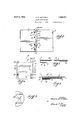
- Fig. 1 is a perspective View of a loose leaf binder embodying my invention.
- Fig. 2 is an elevation of the binding member before the covers are attached.
- Fig. 3 is an enlarged section taken on line 33 of Fig. 2.
- Fig. 4 is an elevation of the binder showing the opposite side to that shown in Fig. 2.
- Fig. 5 is a view similar to Fig. 4 showing the'binder as attached to the binder cover.
- Fig. 6 is an elevation of the binder show ing the binder board in place.
- Fig. 7 is an enlarged section taken on line 77 of Fig. 6.
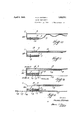
- Fig. 8 is a section similar to Fig. 3 taken through the binder with the paper sheets and binder board in place.
- Fig. 9 shows how the paper sheets and binder board are notched to fit over the binder straps.
- Fig. 10 is an enlarged section similar to Fig. 3 showing the flap in position to receive the binder board in the binder.
- Fig. 11 is a similar view showing the bind- 5 er board in position.
- Fig. 12 is a view similar to Fig. 11 showing the binder cover secured in position.
- Fig. 13 is a section showing the first step in securing the binder cover to thebinder.
- the binder is shown more particularly in Fig. 2 and consists of a binder back 1 to which the covers are attached to form the completed binder.
- This binder as shown in Fig. 2, comprises the binder back 1 which is provided with a return-bent flap 2 as shown in Fig. 3.
- a fabric strap 3 is provided at the top and bottom of the binder and these straps 3 are secured between the flap 2 and the binder back 1 by the wire fasteners 4.
- the binder back bends along the score 11 so that the flap 6, stiffening strip 7 and tongue 10 are in 75 spaced relation with the binder back 1 and as this lifting movement of the flap 6 is forward the straps 3 are slack when in this position.
- a binder board 12 having notches 13 is positioned over the straps 3 and the binder board, as shown in Fig. 11, is moved into engagement with the end 23 of the binder. This takes up the slack in the straps 3 and the portion of the'straps 3 between the stiffening strip 7 and the binder board 12" is the portion of the binder which carries the paper sheets.
- this board is provided with a portion 14 shown in Fig. 6 which is inserted beneath the flap 2between the straps 3 and as this is a fiber board a finger hole 15 is pro.- vided by which the board may be graspe'd'and bent slightly to insert the end 14 beneath the o6 fla 2.
- the finger is inserted in the opening 15 in the fiber board 12 and by bendingthis board slightly the end 1 1 may be disengaged from beneath the flap 2 at which timethe board 12 may be drawn outwardly along the straps 3 so that the straps 3 are then slack.
- the paper sheets for use in the binder areprovided with notches 13 to fit over the straps 3 as shown in Figs. 6 and 9, the same as the binder board 12.
- binders are usually sold to printers so that the printers may put their own covers thereon.
- a cover 17 is provided which is scored with three parallel lines 20, 21 and 22 as shown in Figs. 5, 12 and 13 and the binder, as shown in Fig. 10, is positioned in the cover with the end 23 registering with the scores 20 and 21 as shown.
- the back 1 of the binder is provided with four apertures 18 and as shown in Fig. 13 these apertures 18 allow the wire fasteners 19 to be inserted therethrough and through the stiffening strip 7 and flap 6 and cover 17 to secure the cover to the binder.
- the cover is bent at the score marks 20 and 21 to bring the cover around the binder as shown in Fig. 12.
- the loose sheets may be inserted in the binder and the board 12 positioned in looking position at which time the binder is ready for use.
- the front of the binder cover may be then bent from the score 22 as shown in Fig. 1 at which time the sheets are available for use.
- the advantages of this binder are that the binders may be shipped flat in large quantities and the printers can make up the covers for individual customers of any desired material and with any printing desired thereon so that the printer is able to sell his customer a complete binder arranged for his individual use.
- This device is also adapted for use in hospitals in which each binder is used to contain the record sheets of a certain patient.
- the binder is used without the covers and where a large institution is equipped with these binders a supply of binder boards 12 are kept on hand at different collecting points where the records of the cases are made up or filed.
- cone hospital may use five hundred binder or stiffening boards 12 which may be made of hard fiber or even metal, if desired, and at the same time the hospital may have five thousand binders.
- a binder as shown in Fig. 2, is taken out of stock and the difi'erent record sheets are then inserted in the binder and the binder board is then positioned in the binder to hold the record sheets in place.
- the binder board is removed and the binder which is of flexible material may be then rolled up with the record sheets therein and placed in a carrier in a pneumatic tube system by which it is conveyed to the filing otfice and the binders are there filed in the different files without the binder boards therein.
- the binders of course, can be made up very cheap ly and the binder boards are made of more permanent material such as hard fibre or metal so as to stand a great amount of use.
- a binder back having a return-bent flap at one edge, an inturned flap at the opposite edge of the binder back, a stiffening strip secured to the inturned flap, a pair of straps secured at one end between the stifi'ening strip and inturned flap, the opposite ends of the straps being secured between the return-bent flap and the binder back, the straps being adapted to receive a series of sheets notched to engage thereover, a binder board notched to engage over the straps and movable beneath the inturned flap to bindingly engage the sheets on the straps between the binder board and the stiffening strip, the binder board being provided with a portion insertible beneath the return bent flap between the two straps to hold the binder board in binding position,
- A. loose leaf binder comprising a binder back having a return-bent flap at one edge, an inturned flap at the opposite edge of the binder back, a pair of straps secured to the inturned flap at one end and to the return bent flap at the opposite end, the straps being normally slack, a series of sheets notched to engage over the straps and a binder board notched to engage over the straps beneath the said sheets, the binder board being adapted to be moved to position beneath the inturned flap to take up the slack in the straps and bindingly hold the sheets between the v flap at the opposite edge of the binder back,
- a pair of straps secured atone end to the inturned flap, the opposite ends of the straps being secured between the return-bent flap and the binder back, the straps being adapted to receive a series of sheets notched to engage thereover, a binder board notched to engage over the straps and movable beneath the inturned flap to bindingly engage the sheets on the straps between the binder board and the inturned flap, the binder board being provided with a portion insertible beneath the return-bent flap to hold it in position, and a binder cover secured to the said inturned flap.
- a loose leaf binder comprising a rectangular binder back having an inturned flap at each vertical edge, one flap being secured to the binder back and the other flap being free, a pair of straps secured in spaced relation to the free flap, the opposite ends of the straps being secured between the other flap and the binder back, a fiber binder board notched to fit over the straps, a series of sheets notched to fit over the straps and positioned between the binder board and the free flap, the said binder board being adapted to be moved into position beneath the free flap to bindingly engage the sheets on the straps between the free flap and the binder board, and means for securing the binder board in position in the binder.
- a binder back having a return-bent flap at one edge secured thereto, an inturned flap at the opposite edge of the binder back, a pair of straps secured at one end to the inturned flap, the opposite ends of the straps being secured between the return-bent flap and the binder back, the straps being adapted to receive a series of sheets notched to engage thereover, a binder board notched to engage over the straps and movable beneath the inturned flap to bindingly engage the sheets on the strap between the binder board and the inturned flap.
- a binder back having an inturned flap at one edge, a pair of straps secured at one end to the inturned flap, the opposite ends of the straps being secured to the binder back, the straps being adapted to receive a series of sheets notched to engage thereover, a binder board notched to engage over the straps and movable beneath the inturned flap to bindingly engage the sheets on the straps between the binder board and the inturned flap 7.
- a loose leaf binder In a loose leaf binder, a binder back, a pair of straps secured at one end to the said back, the straps being adapted to receive a series of sheets notched at one edge to engage thereover, a binder board notched at one edge to engage over the straps and being movable toward the secured ends of said strap to bind the series of sheets on the back, and means for detachably holding the binder board in binding position the opposite ends of the straps being secured to the binder back at a distance from the first-named ends whereby the straps are held substantially taut by the binder board on movement thereof to binding position.
Description
April 5, D CQTTRELL LOOSE LEAF BINDER Filed Nov. 14, 1929 3 Sheets-Sheet 1 INVENTOR. .6 5 5 By flaw/v0} 0772/14 A TTORNEY.
April 5, 1932. COTTRELL 1,852,701
LOOSE LEAF BINDER Filed Nov. 14, 1929 3 Sheets-Sheet 2 INVENTOR. x/f am/w Z Car/72:4
A TTORNE Y.
April 5, 1932. H. D. COTTRELL LOOSE LEAF BINDER Fil'ed Nov. 14, 1929 3 Sheets-Sheet 3 eff/0 JCOEE 20 /9 7 I N VEN TOR.
ATT
Patented Apr. 5, 1932 HOLLAND D. COTTLRELL; F DETROITQMIOHIGAN Loosr. LEAF 31mm Application filed November 14, 1929. Serial No. 407,076
This invention relates to loose leaf binders and the object of the invention is to provide a loose leaf binder to which covers of any type may bereadily attached.
Another object of the invention is to provide a binder in which the binding element is built up and may be sold to printers to be fastened in covers, made up by the printers for individual clients with any printing on the cover required by the clients.
Another object of the invention is to provide an arrangement whereby the sheets may be readily removed or replaced within the binder.
These objects and the several novel features of the invention are hereinafter more fully described and claimed and the preferred form of construction by which these objects are attained is shown in the accompanying drawings in which- Fig. 1 is a perspective View of a loose leaf binder embodying my invention.
Fig. 2 is an elevation of the binding member before the covers are attached.
Fig. 3 is an enlarged section taken on line 33 of Fig. 2.
Fig. 4 is an elevation of the binder showing the opposite side to that shown in Fig. 2.
Fig. 5 is a view similar to Fig. 4 showing the'binder as attached to the binder cover.
Fig. 6 is an elevation of the binder show ing the binder board in place.
Fig. 7 is an enlarged section taken on line 77 of Fig. 6.
Fig. 8 is a section similar to Fig. 3 taken through the binder with the paper sheets and binder board in place.
Fig. 9 shows how the paper sheets and binder board are notched to fit over the binder straps.
Fig. 10 is an enlarged section similar to Fig. 3 showing the flap in position to receive the binder board in the binder.
Fig. 11 is a similar view showing the bind- 5 er board in position.
Fig. 12 is a view similar to Fig. 11 showing the binder cover secured in position.
Fig. 13 is a section showing the first step in securing the binder cover to thebinder.
The binder is shown more particularly in Fig. 2 and consists of a binder back 1 to which the covers are attached to form the completed binder. This binder, as shown in Fig. 2, comprises the binder back 1 which is provided with a return-bent flap 2 as shown in Fig. 3. A fabric strap 3 is provided at the top and bottom of the binder and these straps 3 are secured between the flap 2 and the binder back 1 by the wire fasteners 4.
Two extra wire fasteners 5 are also inserted through the flap 2 to firmly secure the flap to the binder back at the ends. At the opposite edge of the binder a flap 6 is inturned and the straps 3 are positioned between the flap 6 and a stiffening strip 7 as shown in Fig. 3 and wire fasteners 8 are clipped through the flap 6, straps 3, stifiening member 7 and the binder back 1. As will be noted from Fig. 4 the binder back is cut out at 9 to provide two tongues 10 through which the wire clips 8 are fastened and the binder back is scored at 11 so as to fold along this line. Thus when the flap 6 is lifted, as shown in Fig. 10, the binder back bends along the score 11 so that the flap 6, stiffening strip 7 and tongue 10 are in 75 spaced relation with the binder back 1 and as this lifting movement of the flap 6 is forward the straps 3 are slack when in this position. When the binder has been arranged in the position shown in Fig. 10 a binder board 12 having notches 13 is positioned over the straps 3 and the binder board, as shown in Fig. 11, is moved into engagement with the end 23 of the binder. This takes up the slack in the straps 3 and the portion of the'straps 3 between the stiffening strip 7 and the binder board 12" is the portion of the binder which carries the paper sheets. To lock the binder board 12 in place this board is provided with a portion 14 shown in Fig. 6 which is inserted beneath the flap 2between the straps 3 and as this is a fiber board a finger hole 15 is pro.- vided by which the board may be graspe'd'and bent slightly to insert the end 14 beneath the o6 fla 2.
To insert the paper sheets in the binder the finger is inserted in the opening 15 in the fiber board 12 and by bendingthis board slightly the end 1 1 may be disengaged from beneath the flap 2 at which timethe board 12 may be drawn outwardly along the straps 3 so that the straps 3 are then slack. The paper sheets for use in the binder areprovided with notches 13 to fit over the straps 3 as shown in Figs. 6 and 9, the same as the binder board 12. A number of these sheets are engaged over the straps 3 between the binder board 12 and the stiffening strip 7 and the binder board is then moved back against the end 23 of the binder thus putting the straps 3 under tension and forcing the paper sheets to position on the straps 3 between the stiffening strip 7 and the fiber board 12, as will be understood from Figs. 8 and 12. These paper sheets 16, as shown in Fig. 1, extend to the outer edge of the binder and it will be seen that by disengaging the binder board 12, the straps 3 may be slackened at any time to allow removal or addition of paper sheets. These binders are made up without covers as shown and are shipped fiat in the form shown in Figs. 2 and 3 and the binder boards 12 are shipped separate from the binders but in the same pack age therewith.
These binders are usually sold to printers so that the printers may put their own covers thereon. For this purpose a cover 17 is provided which is scored with three parallel lines 20, 21 and 22 as shown in Figs. 5, 12 and 13 and the binder, as shown in Fig. 10, is positioned in the cover with the end 23 registering with the scores 20 and 21 as shown. It will be noted that the back 1 of the binder is provided with four apertures 18 and as shown in Fig. 13 these apertures 18 allow the wire fasteners 19 to be inserted therethrough and through the stiffening strip 7 and flap 6 and cover 17 to secure the cover to the binder. When this has been done the cover is bent at the score marks 20 and 21 to bring the cover around the binder as shown in Fig. 12. At this time the loose sheets may be inserted in the binder and the board 12 positioned in looking position at which time the binder is ready for use. The front of the binder cover may be then bent from the score 22 as shown in Fig. 1 at which time the sheets are available for use. The advantages of this binder are that the binders may be shipped flat in large quantities and the printers can make up the covers for individual customers of any desired material and with any printing desired thereon so that the printer is able to sell his customer a complete binder arranged for his individual use.
This device is also adapted for use in hospitals in which each binder is used to contain the record sheets of a certain patient. In this type of use the binder is used without the covers and where a large institution is equipped with these binders a supply of binder boards 12 are kept on hand at different collecting points where the records of the cases are made up or filed. For instance,cone hospital may use five hundred binder or stiffening boards 12 which may be made of hard fiber or even metal, if desired, and at the same time the hospital may have five thousand binders. In this use a binder, as shown in Fig. 2, is taken out of stock and the difi'erent record sheets are then inserted in the binder and the binder board is then positioned in the binder to hold the record sheets in place. After the record is completed and the patient discharged from the hospital the binder board is removed and the binder which is of flexible material may be then rolled up with the record sheets therein and placed in a carrier in a pneumatic tube system by which it is conveyed to the filing otfice and the binders are there filed in the different files without the binder boards therein. In this use the binders, of course, can be made up very cheap ly and the binder boards are made of more permanent material such as hard fibre or metal so as to stand a great amount of use.
From the foregoing description it becomes evident that the device is very simple and efficient in operation, will not easily get out of order, may be very cheaply made and pro vides a device which accomplishes the objects described.
Having thus fully described my invention, its utility and mode of operation, what I claim and desire to secure by Letters Patent of the United States is- 1. In a loose leaf binder, a binder back having a return-bent flap at one edge, an inturned flap at the opposite edge of the binder back, a stiffening strip secured to the inturned flap, a pair of straps secured at one end between the stifi'ening strip and inturned flap, the opposite ends of the straps being secured between the return-bent flap and the binder back, the straps being adapted to receive a series of sheets notched to engage thereover, a binder board notched to engage over the straps and movable beneath the inturned flap to bindingly engage the sheets on the straps between the binder board and the stiffening strip, the binder board being provided with a portion insertible beneath the return bent flap between the two straps to hold the binder board in binding position,
and a binder cover secured to the said inturned flap and stiffening strip and providing a cover for the binder.
2. A. loose leaf binder comprising a binder back having a return-bent flap at one edge, an inturned flap at the opposite edge of the binder back, a pair of straps secured to the inturned flap at one end and to the return bent flap at the opposite end, the straps being normally slack, a series of sheets notched to engage over the straps and a binder board notched to engage over the straps beneath the said sheets, the binder board being adapted to be moved to position beneath the inturned flap to take up the slack in the straps and bindingly hold the sheets between the v flap at the opposite edge of the binder back,
a pair of straps secured atone end to the inturned flap, the opposite ends of the straps being secured between the return-bent flap and the binder back, the straps being adapted to receive a series of sheets notched to engage thereover, a binder board notched to engage over the straps and movable beneath the inturned flap to bindingly engage the sheets on the straps between the binder board and the inturned flap, the binder board being provided with a portion insertible beneath the return-bent flap to hold it in position, and a binder cover secured to the said inturned flap.
4. In a loose leaf binder comprising a rectangular binder back having an inturned flap at each vertical edge, one flap being secured to the binder back and the other flap being free, a pair of straps secured in spaced relation to the free flap, the opposite ends of the straps being secured between the other flap and the binder back, a fiber binder board notched to fit over the straps, a series of sheets notched to fit over the straps and positioned between the binder board and the free flap, the said binder board being adapted to be moved into position beneath the free flap to bindingly engage the sheets on the straps between the free flap and the binder board, and means for securing the binder board in position in the binder.
5. In a loose leaf binder, a binder back having a return-bent flap at one edge secured thereto, an inturned flap at the opposite edge of the binder back, a pair of straps secured at one end to the inturned flap, the opposite ends of the straps being secured between the return-bent flap and the binder back, the straps being adapted to receive a series of sheets notched to engage thereover, a binder board notched to engage over the straps and movable beneath the inturned flap to bindingly engage the sheets on the strap between the binder board and the inturned flap.
6. In a loose leaf binder, a binder back having an inturned flap at one edge, a pair of straps secured at one end to the inturned flap, the opposite ends of the straps being secured to the binder back, the straps being adapted to receive a series of sheets notched to engage thereover, a binder board notched to engage over the straps and movable beneath the inturned flap to bindingly engage the sheets on the straps between the binder board and the inturned flap 7. In a loose leaf binder, a binder back, a pair of straps secured at one end to the said back, the straps being adapted to receive a series of sheets notched at one edge to engage thereover, a binder board notched at one edge to engage over the straps and being movable toward the secured ends of said strap to bind the series of sheets on the back, and means for detachably holding the binder board in binding position the opposite ends of the straps being secured to the binder back at a distance from the first-named ends whereby the straps are held substantially taut by the binder board on movement thereof to binding position.
In testimony whereof I sign this specification.
HOLLAND D. OOTTRELL.
Priority Applications (1)
| Application Number | Priority Date | Filing Date | Title |
|---|---|---|---|
| US407076A US1852701A (en) | 1929-11-14 | 1929-11-14 | Loose leaf binder |
Applications Claiming Priority (1)
| Application Number | Priority Date | Filing Date | Title |
|---|---|---|---|
| US407076A US1852701A (en) | 1929-11-14 | 1929-11-14 | Loose leaf binder |
Publications (1)
| Publication Number | Publication Date |
|---|---|
| US1852701A true US1852701A (en) | 1932-04-05 |
Family
ID=23610491
Family Applications (1)
| Application Number | Title | Priority Date | Filing Date |
|---|---|---|---|
| US407076A Expired - Lifetime US1852701A (en) | 1929-11-14 | 1929-11-14 | Loose leaf binder |
Country Status (1)
| Country | Link |
|---|---|
| US (1) | US1852701A (en) |
-
1929
- 1929-11-14 US US407076A patent/US1852701A/en not_active Expired - Lifetime
Similar Documents
| Publication | Publication Date | Title |
|---|---|---|
| US2127619A (en) | Book assembly | |
| US5445467A (en) | Binding file | |
| US1852701A (en) | Loose leaf binder | |
| US2151717A (en) | Vertical file folder | |
| US1755604A (en) | Binder | |
| US3466133A (en) | Insert sheet for file folders having a paper fastening device thereon | |
| US1603538A (en) | Combined paper holder, loose-leaf binder, and perforator | |
| US1770325A (en) | Loose-leaf-sample system | |
| US2741495A (en) | Memorandum pad binders | |
| US667479A (en) | Record-book. | |
| US2626817A (en) | Loose-leaf sheet calendar hanger | |
| US1903206A (en) | Index | |
| US1619760A (en) | Index element | |
| US1883754A (en) | File | |
| US1973796A (en) | Loose leaf binder | |
| US1944620A (en) | Binder | |
| US699789A (en) | Temporary binder. | |
| US983090A (en) | Billing device. | |
| US325625A (en) | Permanent and temporary letter-file | |
| US2014020A (en) | Counter sales book | |
| US2178449A (en) | Card-holding clip | |
| US192109A (en) | Improvement in temporary binders | |
| US2083432A (en) | Refill book | |
| US2302171A (en) | Loose-leaf binder | |
| US1194422A (en) | Card system |