US1852697A - Cut-out - Google Patents
Cut-out Download PDFInfo
- Publication number
- US1852697A US1852697A US75828A US7582825A US1852697A US 1852697 A US1852697 A US 1852697A US 75828 A US75828 A US 75828A US 7582825 A US7582825 A US 7582825A US 1852697 A US1852697 A US 1852697A
- Authority
- US
- United States
- Prior art keywords
- casing
- fuse
- plug
- circuit
- connector
- Prior art date
- Legal status (The legal status is an assumption and is not a legal conclusion. Google has not performed a legal analysis and makes no representation as to the accuracy of the status listed.)
- Expired - Lifetime
Links
- 239000004020 conductor Substances 0.000 description 10
- 239000003245 coal Substances 0.000 description 3
- 230000003137 locomotive effect Effects 0.000 description 3
- 239000002184 metal Substances 0.000 description 3
- 229910052729 chemical element Inorganic materials 0.000 description 2
- 239000011810 insulating material Substances 0.000 description 2
- 238000007789 sealing Methods 0.000 description 2
- 208000027418 Wounds and injury Diseases 0.000 description 1
- 238000005299 abrasion Methods 0.000 description 1
- 230000015572 biosynthetic process Effects 0.000 description 1
- 230000008878 coupling Effects 0.000 description 1
- 238000010168 coupling process Methods 0.000 description 1
- 238000005859 coupling reaction Methods 0.000 description 1
- 230000006378 damage Effects 0.000 description 1
- 238000010586 diagram Methods 0.000 description 1
- 238000004880 explosion Methods 0.000 description 1
- 239000002360 explosive Substances 0.000 description 1
- 239000004744 fabric Substances 0.000 description 1
- 208000014674 injury Diseases 0.000 description 1
- 238000009434 installation Methods 0.000 description 1
- 238000009413 insulation Methods 0.000 description 1
- 238000004519 manufacturing process Methods 0.000 description 1
- 239000000463 material Substances 0.000 description 1
- 238000005065 mining Methods 0.000 description 1
- 230000001105 regulatory effect Effects 0.000 description 1
- 238000000926 separation method Methods 0.000 description 1
Images
Classifications
-
- H—ELECTRICITY
- H01—ELECTRIC ELEMENTS
- H01H—ELECTRIC SWITCHES; RELAYS; SELECTORS; EMERGENCY PROTECTIVE DEVICES
- H01H9/00—Details of switching devices, not covered by groups H01H1/00 - H01H7/00
- H01H9/10—Adaptation for built-in fuses
- H01H9/102—Fuses mounted on or constituting the movable contact parts of the switch
Definitions
- a further object is to provide apparatus such as above described with means to insure against accidental or unauthorized admission of the external atmosphere to the interior of the casing.
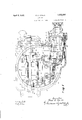
- Fig. 1 is a front elevational view oi' the prei ferred embodiment of my invention, showing the front cover removed and certain parts of the casing broken away to reveal the interior mechanism.
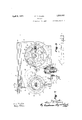
- Fig. 2 is an end view of the apparatus disclosed in Fig. 1, partly in section, with the operating handle andr top cover plate removed to reveal the interior mechanism.
- Fig. 3 is a diagrammatic illustration of an electric circuit which includes my improved cut-out.
- the numeral 2 indicates, as an entirety, a cutout of the class to which my invention relates.
- the numeral 3 indicates a controller of the common and well known type whereby the flow of electric current may be regulated in the motor Il. rlhe battery 1 is connected with the cut-out 2 by two conductors 5 and 6 which are preferably encased in a flexible conductor cable of the type commonly used in coal mining apparatus, and the cutout 2 is connected with the controller 3 and motor l through the conductors 7 and 8 which are preferably a part of the permanent wiring of the locomotive.
- the numeral 9 refers to a casing which is preferably formed of cast metal, but which may, if desired, be fabricated in any other convenient manner.
- the casing 9 has a relatively large circular window at its front side to aord access to the mechanism mounted within.
- On the edge 10 of the circular window are formed screw threads adapted to engage corresponding threads formed on an annular flange 11 of the circular cover plate 12.
- Formed on the cover plate 12 and projecting; beyond the annular flange 11. is a circular flange 13 the face of which is finished to engage a correspondingly finished face of the casing 9 to form a gas tight joint when the cover plate l2 is screwed firmly to place.
- the flange 13 is notched at 14 to receive the hasp of a padlocl 15 when it is placed upon the studs 16 of the casing, and by that engagement prevents rotation of the plate in the unscrewing direction to break the seal of the casing.
- T 9 Formed in one end of the casing,T 9 is a second circular aperture having a cover plate 17 screw threaded in place and adapted to form a gas tight joint in the same manner as that above described.
- a ournal bearing ⁇ 1S At the center of the cover plate 17 there is formed a ournal bearing ⁇ 1S in which is rotatively mounted a shaft 19 which projects on both sides of said cover plate.
- the cover plate 17 is in operative position, the inner end of the shaft 19 is engaged by a journal bearing ⁇ 2O formed in the metal of the opposite wall of the casing, and to the outer end of this shaft 19 is fined an operating handle 21 whereby said shaft may be conveniently rotated.
- the middle portion 22 of the shaft 19, between the journal bearings 18 and 20, is preferably formed square for the more convenient attachment of parts intended to rotate with the shaft and this square portion 22 is preferably encased in an insulating sleeve 23 to insure against its accidental connection with the electrically charged parts of the apparatus.
- Mounted upon the square portion 22 of the shaft 19 are two suitably shaped blocks 24 and 25 formed of suitable insulating material, and spaced apart longitudinally of the shaft, to each of which is attached a plurality of metal plates 26.
- a spring clip 27 adapted to receive and securely hold in place the metallic terminals 28 and 29 of the fuse cartridge 30 of the common and well known type.
- the brushes 34 and 35 are of the type commonly used in electric controllers and similar apparatus, and are adapted to simultaneously contact with the terminals 28 and 29 of one of the fuse cartridges 30, in such manner that by rotation of the shaft 19 the cartridges 30 may be successively connected between the brush holders 32 and 33.
- the brush holders 32 and 33 are each provided with clamping members 36 and 37 whereby permanent connection is made with the conductors 7 and 38.
- a removable plug 39 having, in this instance, two contact members 40 and 41 which are normally soldered to the ends of the conductors 5 and 6 of the flexible conductor cable abovereferred to.
- the contact members 4() and 41 are adapted to engage with metallic studs 42 and 43 supported upon an insulating base 44 positioned in the cylindrical extension 45 of the casing.
- a flange 46 formed upon the plug 39 projects over Vthe end of the cylindrical extension 45 and this flange is engaged by a ring 47 which is screw threaded and adapted to engage corresponding threads formed on the outside or' the extension 45 to securelyhold the plug 39 in its operative position.
- a collar 48 pinned to the plug 39 prevents ythe accidental separation of ythe ring 47 from the plug 39, and on this collar is formed a plurality ot radially extending proj ections 49 each adapted to engage the hasp of a padlock 50 when it is in place upon a lug 51 formed on the ring 47.
- a conductor 38 extends from the stud 43 to the brush holder 32, and the other stud 42 is in permanent connection with the conductor 8 of the locomotive circuit.
- the battery 1 may be connected with the controller 3 and lnotor 4 in such manner as to include one of the fuses 30, and thereby protect the apparatus from injury by an excessive flow of electric current.
- interlocking mechanism connecting said plug with the shaft 19, comprising a rod 53 one end of which is slidable in a bearing 54 of the casing, and the other end is pivotally attached to one arm of a bell crank 55 which is mounted upon the pvot 56 of the casing.
- a bell crank 55 On the arm 57 of the bell crank 55 are formed iingers adapted to engage a lug 58 formed upon the side of the plug 39, in such manner that when said plug is in operative position the rod 53 will be held at one extremity of its longitudinal movement.
- a spring 59 is arranged to hold said rod at its other limit of longitudinal movement when moved thereto upon withdrawal of plug 39 from the casing.
- a lug 60 formed on the rod 53 is adapted, by its engagement with an aperture 61 in the collar 62 fixed to thc shaft 19, when the plug is withdrawn, to prevent rotation of said shaft, and the parts are so shaped and arranged as to prevent withdrawal of the plug 39 when the shaft 19 is so turned that the aperture 61 is out of alignment with the plug 60.
- the plug 39 may not be withdrawn from the cylindrical extension 45 of the casing while the brushes 34 and 35 are in contact with t-he terminals 28 and 29 of the fuse cartridge 30, nor can the fuse cartridge 30 be moved into connection with the brushes 34 and 35 while the plug 39 is withdrawn from the casing.
- conduits 63 extending from the casing 9 of the cut-out 2 to the gas tight casing of the controller 3 and the motor 4.
- These conduits 63 are preferably formed of iexible tubing
- a coupling tting having a sleeve @el which closely fits the outside of the conduit, and a flange 65 which is faced to forni a tight joint with a suitable finished surrace surrounding an aperture 66 of the casing 9, and is securely clamped thereto by suitable machine Screws 67.
- annular flanges 63 adapted to be forced into the material of the conduit by the expansion of a thimble 69 which is rolled into the conduit when the parts are assembled., to secur ij hold the parts together and insure the joint against leakage.
- a projecting end 70 of the conduit extends through the aperture 66 to afford mechanical protection to the installation of the conductor.
- connections of with the casing of the conthe conduits 6o troller, motor, or other elements of the apparatus may be made in the same manner as with the cutout 2, thereby providing ⁇ a complete unitary system of protection from explosion for the entire apparatus, whereby the said apparatus may be protected, not only from accidental ignition of the gas charged atmosphere, but also from unauthorized or malicious tampering with the protecting agencies.
- a switch device including a rotary element, a separable connector adapted to connect said device with an electric circuit, said-connector comprising fixed and movable elements, a locking lug reciprocable radially of said rotary element and moved in one direction upon disengagement of the movable element of said connector to immediately enter a radial recess in the rotary element of said switch device to lock it, said locking lug being returned to release position upon the operative re-engagement of said movable element.
- a switch device including a movable element a separable connector adapted to connect said switch device with an electric circuit ⁇ said connector comprising fixed and movable elements, a reiprocable locking bar having a lug at one end adapted to engage in a recess in the movable element of said switch device to lock the latter, a bell crank at the other end of said locking bar having one arm in pivotal connection therewith, the other arm of said cranlr being engaged by the movable element of said connector whereby upon disengagement of the latter said bar is moved into locking position and upon re-engagement thereof is moved to release position.
- a switch device including a movable element, a separable connector adapted to connect said switch device with an electric circuit, said connector comprisingl fixed and movable elements, a. reciprocable locking bar having a lug at one end adapted to engage in a recess in the movable element of said switch device to lock the latter, bell crank at the other end of said loclring bar having one arm in pivotal connection therewith, the other arm of said crank being engaged by the movable element of said connector whereby upon disengagement of the latter said bar is moved into locking position and upon reengagement thereof is moved to release posi-l tion, such movement of said bar being permitted only when said switch device is in off position.
- a circuit closing device including a rotary element, separable connector adapted to connect said switch device with an electric circuit, said connector comprising iixed and movable elem-ents, a reciprocable locking bar having an offset lug at one end radial to said rotary element and adapted to engage in a radial recess in said rotary element to lock the latter, a slide bearing for said bar at said end thereof, a bell crank at the other end of said bar having one arm in pivotal connection therewith, the other arm of said crank being engaged by the movable element of said connector whereby disengaging movement of the latter relative to the fixed elem-ent is positively transmitted to said lug to engage it in said recess and re-engaging movement of said movable element is positively transmitted to said lug to rel-ea e it from said recess.
- a gas-proof casing fuse carrying means moun ed within the casing,fuses carried by said carrying means, means operable from the exterior of the casing to move said carrying means to bring a fuse into circuit or to move a fuse out of the circuit, a separable connector in the circuit comprising ⁇ a fixed portion in the casing and accessible through an aperture in the casing, said connector also comprising a movable portion enoageable with and disengageable from the fixed.
- a gas-proof casing,fuse carrying means mounted within the casing, fuses carried by said ca vying means,means operable from the exterior of the casing to move said carrying moans to bring a fuse into a circuit or to move a fuse out of the Circuit
- a separable connector in the circuit-comprising a fixed portion in the casing and accessible through an aporture in the casing said connector also coinrprising a movable portion engageable with and disenga'eable from the fixed portion and sealing said aperture
- a single interlocking train between said movable portion and the fuse carrying means to prevent disengaging 1noVement of said movable portion When a fuse is in the circuit and to prevent the inter-position of a fuse in the circuit when said movable portion is disengaged.
Landscapes
- Connector Housings Or Holding Contact Members (AREA)
Description
F. C. COSEO April 5, 1932.
CUT- OUT Filed Dec. 16, 1925 2 Sheets-Sheet F. C, COSEO April 5, 1932.
CUT-OUT Filed Deo. 1G 1925 2 Sheets-Sheet 2 I En" Patented Apr. 5, 1933 .STTES ATNT @FFCE FRED C.A COSEO, OF COLUMBUS, OHIO, ASSIG-NOB TO THE JEFFREY MANUFACTURING COM- PANY, F COLUMBUS, OHIO, A CORPORATION F Ofi-I0 CUT-OUT Application filed December 16, 1925. Serial No. 75,828.
c a coal mine from Contact with elements subject to electric charge, and having means whereby the successive fuses may be connected into a circuit without admitting the mine atmosphere to the interior of the casing.
A further object is to provide apparatus such as above described with means to insure against accidental or unauthorized admission of the external atmosphere to the interior of the casing.
The means whereby I attain these objects are fully set forth in the following specification and illustrated in the accompanying drawings of which- Fig. 1 is a front elevational view oi' the prei ferred embodiment of my invention, showing the front cover removed and certain parts of the casing broken away to reveal the interior mechanism.
Fig. 2 is an end view of the apparatus disclosed in Fig. 1, partly in section, with the operating handle andr top cover plate removed to reveal the interior mechanism.
Fig. 3 is a diagrammatic illustration of an electric circuit which includes my improved cut-out.
Like numerals refer to similar parts in the several figures.
To facilitate the description of my improved cut-out I have provided.r in 3 of the drawings, a diagrammatic illustration of the principal electric circuits of a locomotive adapted to the haulage of coal in a mine. In this diagram the numeral 1 indicates a storage battery, or other suitable and convenient source of electric current supply.
The numeral 2 indicates, as an entirety, a cutout of the class to which my invention relates. The numeral 3 indicates a controller of the common and well known type whereby the flow of electric current may be regulated in the motor Il. rlhe battery 1 is connected with the cut-out 2 by two conductors 5 and 6 which are preferably encased in a flexible conductor cable of the type commonly used in coal mining apparatus, and the cutout 2 is connected with the controller 3 and motor l through the conductors 7 and 8 which are preferably a part of the permanent wiring of the locomotive. In Figs. 1 and 2 of the drawings the numeral 9 refers to a casing which is preferably formed of cast metal, but which may, if desired, be fabricated in any other convenient manner. The casing 9 has a relatively large circular window at its front side to aord access to the mechanism mounted within. On the edge 10 of the circular window are formed screw threads adapted to engage corresponding threads formed on an annular flange 11 of the circular cover plate 12. Formed on the cover plate 12 and projecting; beyond the annular flange 11. is a circular flange 13 the face of which is finished to engage a correspondingly finished face of the casing 9 to form a gas tight joint when the cover plate l2 is screwed firmly to place. The flange 13 is notched at 14 to receive the hasp of a padlocl 15 when it is placed upon the studs 16 of the casing, and by that engagement prevents rotation of the plate in the unscrewing direction to break the seal of the casing.
Formed in one end of the casing,T 9 is a second circular aperture having a cover plate 17 screw threaded in place and adapted to form a gas tight joint in the same manner as that above described. At the center of the cover plate 17 there is formed a ournal bearing` 1S in which is rotatively mounted a shaft 19 which projects on both sides of said cover plate. hen the cover plate 17 is in operative position, the inner end of the shaft 19 is engaged by a journal bearing` 2O formed in the metal of the opposite wall of the casing, and to the outer end of this shaft 19 is fined an operating handle 21 whereby said shaft may be conveniently rotated. The middle portion 22 of the shaft 19, between the journal bearings 18 and 20, is preferably formed square for the more convenient attachment of parts intended to rotate with the shaft and this square portion 22 is preferably encased in an insulating sleeve 23 to insure against its accidental connection with the electrically charged parts of the apparatus. Mounted upon the square portion 22 of the shaft 19 are two suitably shaped blocks 24 and 25 formed of suitable insulating material, and spaced apart longitudinally of the shaft, to each of which is attached a plurality of metal plates 26. Upon each of the plates 26 is formed a spring clip 27 adapted to receive and securely hold in place the metallic terminals 28 and 29 of the fuse cartridge 30 of the common and well known type. A block of suitable insulating material 31 rigidly attached to the back walls of the casing 9, supports two brush holders 32 and 33 to which are secured the brushes 34 and 35 respectively. The brushes 34 and 35 are of the type commonly used in electric controllers and similar apparatus, and are adapted to simultaneously contact with the terminals 28 and 29 of one of the fuse cartridges 30, in such manner that by rotation of the shaft 19 the cartridges 30 may be successively connected between the brush holders 32 and 33. The brush holders 32 and 33 are each provided with clamping members 36 and 37 whereby permanent connection is made with the conductors 7 and 38.
In the illustration of my invention here presented provision is made for the connection of the cut-out 2 with a source of electric supply by means of a removable plug 39 having, in this instance, two contact members 40 and 41 which are normally soldered to the ends of the conductors 5 and 6 of the flexible conductor cable abovereferred to. The contact members 4() and 41 are adapted to engage with metallic studs 42 and 43 supported upon an insulating base 44 positioned in the cylindrical extension 45 of the casing. These parts are so proportioned that when the plug 39 is thrust into the cylindrical extension 45 to cause the connection of the members 40 and 41 with the studs 42 and 43, said plugs will effectively close said cylindrical extension to prevent the passage of gasses to or from the interior of the casing. A flange 46 formed upon the plug 39 projects over Vthe end of the cylindrical extension 45 and this flange is engaged by a ring 47 which is screw threaded and adapted to engage corresponding threads formed on the outside or' the extension 45 to securelyhold the plug 39 in its operative position. A collar 48 pinned to the plug 39 prevents ythe accidental separation of ythe ring 47 from the plug 39, and on this collar is formed a plurality ot radially extending proj ections 49 each adapted to engage the hasp of a padlock 50 when it is in place upon a lug 51 formed on the ring 47. By such engagement of one oi' the projections 49 with the padlock 50 rotative movement of ring 47 is limited to such an extent as to insure against the unauthorized removal of the plug 39 from the cylindrical extension 45. A conductor 38 extends from the stud 43 to the brush holder 32, and the other stud 42 is in permanent connection with the conductor 8 of the locomotive circuit. By the arrangement of parts above described the battery 1 may be connected with the controller 3 and lnotor 4 in such manner as to include one of the fuses 30, and thereby protect the apparatus from injury by an excessive flow of electric current. If a 'fuse 30 is burned in service, due to overload, rotation of the handle 21 will remove the terminals 28 and 29 of the burnt fuse from contact with the brushes 34 and 35 and move a second fuse 52 into operative relation therewith, restoring the circuit through a suitable fuse without removing the insurance against possible ignition of an explosive atmosphere by the accidental formation of electric arcs at the terminals of the fuse.
To insure the opening of the electric circuit before the removal of the plug 39, I have provided interlocking mechanism connecting said plug with the shaft 19, comprising a rod 53 one end of which is slidable in a bearing 54 of the casing, and the other end is pivotally attached to one arm of a bell crank 55 which is mounted upon the pvot 56 of the casing. On the arm 57 of the bell crank 55 are formed iingers adapted to engage a lug 58 formed upon the side of the plug 39, in such manner that when said plug is in operative position the rod 53 will be held at one extremity of its longitudinal movement. A spring 59 is arranged to hold said rod at its other limit of longitudinal movement when moved thereto upon withdrawal of plug 39 from the casing. A lug 60 formed on the rod 53 is adapted, by its engagement with an aperture 61 in the collar 62 fixed to thc shaft 19, when the plug is withdrawn, to prevent rotation of said shaft, and the parts are so shaped and arranged as to prevent withdrawal of the plug 39 when the shaft 19 is so turned that the aperture 61 is out of alignment with the plug 60. By this arrangement of parts the plug 39 may not be withdrawn from the cylindrical extension 45 of the casing while the brushes 34 and 35 are in contact with t- he terminals 28 and 29 of the fuse cartridge 30, nor can the fuse cartridge 30 be moved into connection with the brushes 34 and 35 while the plug 39 is withdrawn from the casing.
In ordeil to complete the gas prootl enclosure of the apparatus, I have provided conduits 63 extending from the casing 9 of the cut-out 2 to the gas tight casing of the controller 3 and the motor 4. These conduits 63 are preferably formed of iexible tubing,
such for example as rubber and fabric hose, which is impervious to gas and affords desirable mechanical protection against abrasion of the insulation of the enclosed conductors. Adjacent the end of the conduit 63 is placed a coupling tting having a sleeve @el which closely fits the outside of the conduit, and a flange 65 which is faced to forni a tight joint with a suitable finished surrace surrounding an aperture 66 of the casing 9, and is securely clamped thereto by suitable machine Screws 67. @n the inner surface of the sleeve 64 there are formed one or more annular flanges 63 adapted to be forced into the material of the conduit by the expansion of a thimble 69 which is rolled into the conduit when the parts are assembled., to secur ij hold the parts together and insure the joint against leakage. A projecting end 70 of the conduit extends through the aperture 66 to afford mechanical protection to the installation of the conductor. The connections of with the casing of the conthe conduits 6o troller, motor, or other elements of the apparatus, may be made in the same manner as with the cutout 2, thereby providing` a complete unitary system of protection from explosion for the entire apparatus, whereby the said apparatus may be protected, not only from accidental ignition of the gas charged atmosphere, but also from unauthorized or malicious tampering with the protecting agencies.
What I claim is 1. In a device of the class described, a switch device including a rotary element, a separable connector adapted to connect said device with an electric circuit, said-connector comprising fixed and movable elements, a locking lug reciprocable radially of said rotary element and moved in one direction upon disengagement of the movable element of said connector to immediately enter a radial recess in the rotary element of said switch device to lock it, said locking lug being returned to release position upon the operative re-engagement of said movable element.
2. In an apparatus of the class described, a switch device including a movable element a separable connector adapted to connect said switch device with an electric circuit` said connector comprising fixed and movable elements, a reiprocable locking bar having a lug at one end adapted to engage in a recess in the movable element of said switch device to lock the latter, a bell crank at the other end of said locking bar having one arm in pivotal connection therewith, the other arm of said cranlr being engaged by the movable element of said connector whereby upon disengagement of the latter said bar is moved into locking position and upon re-engagement thereof is moved to release position.
3. In an apparatus of the class described,
a switch device including a movable element, a separable connector adapted to connect said switch device with an electric circuit, said connector comprisingl fixed and movable elements, a. reciprocable locking bar having a lug at one end adapted to engage in a recess in the movable element of said switch device to lock the latter, bell crank at the other end of said loclring bar having one arm in pivotal connection therewith, the other arm of said crank being engaged by the movable element of said connector whereby upon disengagement of the latter said bar is moved into locking position and upon reengagement thereof is moved to release posi-l tion, such movement of said bar being permitted only when said switch device is in off position.
1l. in an apparatus of the class described, a circuit closing device including a rotary element, separable connector adapted to connect said switch device with an electric circuit, said connector comprising iixed and movable elem-ents, a reciprocable locking bar having an offset lug at one end radial to said rotary element and adapted to engage in a radial recess in said rotary element to lock the latter, a slide bearing for said bar at said end thereof, a bell crank at the other end of said bar having one arm in pivotal connection therewith, the other arm of said crank being engaged by the movable element of said connector whereby disengaging movement of the latter relative to the fixed elem-ent is positively transmitted to said lug to engage it in said recess and re-engaging movement of said movable element is positively transmitted to said lug to rel-ea e it from said recess.
5. In an apparatus of the class described, a gas-proof casing, fuse carrying means moun ed within the casing,fuses carried by said carrying means, means operable from the exterior of the casing to move said carrying means to bring a fuse into circuit or to move a fuse out of the circuit, a separable connector in the circuit comprising` a fixed portion in the casing and accessible through an aperture in the casing, said connector also comprising a movable portion enoageable with and disengageable from the fixed. portion and sealing said aperture when in engaged positon to maintain the gas-proof condition of the casing, and interlocking means between said movable portion and the fuse carrying means to prevent disengaging movement of said movable portion when a fuse is in the circuit and to prevent the interposition of a fuse in the circuit when said movable portion is disengaged.
6. In an apparatus of the class described, a gas-proof casing,fuse carrying means mounted within the casing, fuses carried by said ca vying means,means operable from the exterior of the casing to move said carrying moans to bring a fuse into a circuit or to move a fuse out of the Circuit, a separable connector in the circuit-comprising a fixed portion in the casing and accessible through an aporture in the casing, said connector also coinrprising a movable portion engageable with and disenga'eable from the fixed portion and sealing said aperture When in enga-ged posi tion to `maintain the gas-proof Condition of the casing, and a single interlocking train between said movable portion and the fuse carrying means to prevent disengaging 1noVement of said movable portion When a fuse is in the circuit and to prevent the inter-position of a fuse in the circuit when said movable portion is disengaged.
In testimony7 whereof I have hereunto set my hand.
FRED C. COSEO.
Priority Applications (3)
| Application Number | Priority Date | Filing Date | Title |
|---|---|---|---|
| US75828A US1852697A (en) | 1925-12-16 | 1925-12-16 | Cut-out |
| US313627A US1852698A (en) | 1925-12-16 | 1928-10-19 | Casing for electric apparatus |
| US413625A US1852699A (en) | 1925-12-16 | 1929-12-12 | Cut-out |
Applications Claiming Priority (1)
| Application Number | Priority Date | Filing Date | Title |
|---|---|---|---|
| US75828A US1852697A (en) | 1925-12-16 | 1925-12-16 | Cut-out |
Publications (1)
| Publication Number | Publication Date |
|---|---|
| US1852697A true US1852697A (en) | 1932-04-05 |
Family
ID=22128239
Family Applications (1)
| Application Number | Title | Priority Date | Filing Date |
|---|---|---|---|
| US75828A Expired - Lifetime US1852697A (en) | 1925-12-16 | 1925-12-16 | Cut-out |
Country Status (1)
| Country | Link |
|---|---|
| US (1) | US1852697A (en) |
-
1925
- 1925-12-16 US US75828A patent/US1852697A/en not_active Expired - Lifetime
Similar Documents
| Publication | Publication Date | Title |
|---|---|---|
| US1818290A (en) | Combined switch and terminal block | |
| US1971990A (en) | Electrical apparatus | |
| US3271725A (en) | Electrical connector | |
| US2277671A (en) | Electrical switch | |
| US1852697A (en) | Cut-out | |
| US1783062A (en) | Electric switch | |
| JP2016091794A (en) | Electrical connector | |
| US1852699A (en) | Cut-out | |
| US1188568A (en) | Terminal box and plug. | |
| US1798244A (en) | Isolating plugging-in box for electric power cables | |
| US1762203A (en) | Connecting device for storage batteries | |
| US2646475A (en) | Electric switch and power take-off device | |
| US1300789A (en) | Car and electric coupling device. | |
| US2161571A (en) | Bus bar conduit system | |
| US1370656A (en) | Protective device | |
| US1362049A (en) | Explosion-proof device for electrical apparatus | |
| US2334810A (en) | Power distribution system | |
| US1933506A (en) | Electrical connecting means | |
| US2753408A (en) | Coupling for electric cables | |
| US2273729A (en) | Switch box having plug-in outlet | |
| US1482958A (en) | Electric switch | |
| US2133799A (en) | Circuit control means | |
| US1045572A (en) | Switch and connecting device for electric conductors. | |
| US1451979A (en) | Electric-conductor coupling | |
| US2266663A (en) | Explosionproof plug receptacle |