US1852699A - Cut-out - Google Patents
Cut-out Download PDFInfo
- Publication number
- US1852699A US1852699A US413625A US41362529A US1852699A US 1852699 A US1852699 A US 1852699A US 413625 A US413625 A US 413625A US 41362529 A US41362529 A US 41362529A US 1852699 A US1852699 A US 1852699A
- Authority
- US
- United States
- Prior art keywords
- casing
- strips
- cut
- plug
- cartridge
- Prior art date
- Legal status (The legal status is an assumption and is not a legal conclusion. Google has not performed a legal analysis and makes no representation as to the accuracy of the status listed.)
- Expired - Lifetime
Links
- 239000004020 conductor Substances 0.000 description 11
- 239000007789 gas Substances 0.000 description 10
- 239000003245 coal Substances 0.000 description 3
- 230000003137 locomotive effect Effects 0.000 description 3
- 239000002184 metal Substances 0.000 description 3
- 230000000875 corresponding effect Effects 0.000 description 2
- 238000004880 explosion Methods 0.000 description 2
- 239000002360 explosive Substances 0.000 description 2
- 239000011810 insulating material Substances 0.000 description 2
- 208000027418 Wounds and injury Diseases 0.000 description 1
- 230000015572 biosynthetic process Effects 0.000 description 1
- 230000008878 coupling Effects 0.000 description 1
- 238000010168 coupling process Methods 0.000 description 1
- 238000005859 coupling reaction Methods 0.000 description 1
- 230000006378 damage Effects 0.000 description 1
- 238000010586 diagram Methods 0.000 description 1
- 238000006073 displacement reaction Methods 0.000 description 1
- 239000004744 fabric Substances 0.000 description 1
- 208000014674 injury Diseases 0.000 description 1
- 238000009434 installation Methods 0.000 description 1
- 238000009413 insulation Methods 0.000 description 1
- 238000004519 manufacturing process Methods 0.000 description 1
- 239000000463 material Substances 0.000 description 1
- 238000005065 mining Methods 0.000 description 1
- 230000001105 regulatory effect Effects 0.000 description 1
- 238000000926 separation method Methods 0.000 description 1
Images

Classifications
-
- H—ELECTRICITY
- H01—ELECTRIC ELEMENTS
- H01H—ELECTRIC SWITCHES; RELAYS; SELECTORS; EMERGENCY PROTECTIVE DEVICES
- H01H9/00—Details of switching devices, not covered by groups H01H1/00 - H01H7/00
- H01H9/10—Adaptation for built-in fuses
- H01H9/102—Fuses mounted on or constituting the movable contact parts of the switch
Definitions
- the present invention relates to certain new and useful improvements in cut-outs adapted to the protection of electric circuits, and particularly to cut-outs of the type having sections of readily fusible conductors adapted to be ruptured by excessive flow of current theret-hrough.
- the especial object of this invention is to provide a cut-out having a plurality of fuses adapted to be successively and expeditiously connected into an electric circuit.
- a further object is to provide a cut-out enclosed in a gas tight casing adapted to exclude explosive gas laden atmosphere of a coal mine from contact with elements subject to electric charge, and having means whereby the successive fuses may be connected into a circuit without admitting the mine atmosphere to the interior of the casing.
- a further object is to provide apparatus such as above described with means to insure against accidental or unauthorized admission of the external atmosphere to the interior of the casing.
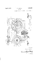
- Fig. 1 is a front elevational view of the preferred embodiment of my invention, showing the front cover removed and certain parts of the casing broken away to reveal the interior mechanism.
- Fig. 2 is an end view of the apparatus disclosed in Fig. 1, partly in section, and having the operating handle and top cover plate removed to reveal the interior mechanism.
- Fig. 3 is a diagrammatic illustration of an electric circuit which includes my improved cutout.
- Fig. 3 of the drawings a diagrammatic illustration of the principal electric circuits of a locomotive adapted to the haulage of coal in a mine.
- the numeral 1 indicates a storage battery, or other suitable and convenient source of electric current supply.
- the numeral 2 indicates, as an entirety, a cut-out of the class to which my invention relates.
- the numeral 3 indicates a controller of the common and well known type whereby the flow of electric current may be regulated in the motor 4.
- the battery 1 is connected with the cut-out 2 by two conductors 5 and 6 which are preferably encased in a flexible conductor cable of the type commonly used in coal mining apparatus, and the cut-out 2 is connected with the controller 3 and motor 4 through the conductors 7 and 8 which are preferably a part of the permanent wiring of the locomotive.
- the numeral 9 refers to a casing which is preferably formed of cast metal, but which may, if de sired, be fabricated in any other convenient manner.
- the casing 9 has a relatively large circular window at its front side to afford access to the mechanism mounted within.
- On the edge. 10 of the circular window are formed screw threads adapted to engage cor responding threads formed on an annular flange 11 of the circular cover plate 12.
- the flange 13 is notched at 14 to receive the hasp of a padlock 15 when it is placed upon the studs 16 of the casing, and by that engagement prevents rotation of the plate in the unscrewing direction to break the seal of the casing.
- a second circular aperture Formed in one end of the casing 9 is a second circular aperture having a cover plate 17 screw threaded in place and adapted to form a gas tight joint in the same manner as that above described. At the center of the cover plate 17 there is formed a ournal bearthe fuses away from the holder.
- ing 18 in which is rotatively mounted a shaft 19 which projects on both sides of said cover plate.
- the inner end of the shaft 19 is engaged by a journal bearing 20 formed in the metal of the opposite wall of the easing, and to the outer end of this shaft 19 is fixed an operating handle 21 whereby said shaft may be conveniently rotated.
- the middle portion 22 of the shaft 19, bet-ween the journal bearings 18 and 20, is preferably formed square for the more convenient attachment of parts intended to rotate with the shaft, and this square portion 22 is preferably encased in an insulating sleeve 23 to in sure against its accidental connection with the electrically charged parts of the apparatus.
- a plurality of metal plates 26 mounted upon the square portion 22 of the shaft 19 .
- a spring clip 27 adapted to re ceive and securely hold in place the axially projecting metallic terminal strips 28 and 29 of the cylindrical fuse cartridge 30 of the common and well known type.
- a block of suitable insulating material 31 rigidly attached to the back walls of the casing 9, supports two brush holders 32 and 33 to which are secured the brushes 34 and 35 respective ly.
- the brushes 34 and 35 are of the type commonly used in electric controllers and similar apparatus, and are adapted to simultaneously contact with the terminals 28 and 29 of one of the fuse cartridges 30, in such manner that by rotation of the shaft 19 the cartridges 30 may be successively connected between the brush holders 32 and 33.
- the brush holders 32 and 33 are each provided with clamping members 36 and 37 whereby permanent connection is made with the conductors 7 and 38.
- block 24 is circular and is provided on its circumferential face with recesses 24 in which the ends 28 of the fuses are seated.
- Block 25 is similar in form to block 24.
- the clips 27 which are positioned above the recesses have offset portions 27' which engage the ends of the terminal strips to prevent longitudinal displacement of the fuses and shoulders 27 which engage over the ends to prevent radial movement of I The terminal strips are released by pressing clips 27 toward plate 26.
- recesses 24 are of such depth that the top lateral edges of the terminal strips are flush with the marginal portions of the block adjacent the recesses, so that the brushes may ride smoothly on and off the strips.
- a removable plug 39 having, in this instance, two contact members 40 and 41 which are normally soldered to the ends of the conductors 5 and 6 of the flexible conductor cable above referred to.
- the contact members 40 and 41 are adapted to engage with metallic studs 42 and 43 supported upon an insulating base 44 positioned in the cylindrical extension 45 of the casing.
- a flange 46 formed upon the plug 39 projects over the end of the cylindrical casing 45 and this flange is engaged by a ring 47 which is screw threaded and adapted to engage corresponding screws formed on the outside of the extension 45 to securely hold the plug 39 in its operative position.
- a collar 48 pinned to the plug 39 prevents the accidental separation of the ring 47 from the plug 39, and on this collar is formed a plurality of radially extending projections 49 each adapted to engage the has p of apadlock 50 when it is in place u on a lug 51 formed on the ring 47. ment of one of the projections 49 with the padlock 5O rotative movement of ring 47 is limited to such an extent as to insure against the unauthorized removal of the plug 39 from the cylindrical extension 45.
- the battery 1 may be connected with the controller 3 and motor 4 in such manner as to include one of the fuses 30, and thereby protect the apparatus from injury by an excessive flow of electric current. If a fuse 30 is burned in service, due to overload,
- a spring 59 is arranged to move said rod longitudinally in the opposite direction when the plug 39 is withdrawn from the casing.
- a lug 60 formed on the rod 53 is adapted, by its engagement with an aperture 61 in the collar 62 fixed to the shaft 19, when the plug is withdrawn, to prevent rotation of said shaft, and the parts are so shaped and arranged as to prevent withdrawal of the plug 39 when the shaft 19 is so turned that the aperture 61 is out of alignment with the plug 60.
- the plug 39 may not be withdrawn from the cylindrical extension 4:5 of the casing while the brushes 34 and 35 are in contact with the terminals 28 and 29 of the fuse cartridge 30, nor can the fuse cartridge 30 be moved into connection wit-h the brushes 34 and 35 while the plug 39 is withdrawn from the casing.
- conduits 63 extending from the casing 9 of the cut-out 2 to the gas tight casing of the controller 3 and the motor 4.
- These conduits 63 are preferably formed of flexible tubing, such for example as rubber and fabric hose, which is impervious to gas and affords desirable mechanical protection againstabrasion of the insulation of the enclosed conductors.
- Adjacent the end of the conduit 63 is placed a coupling fitting having a sleeve 64 which closely fits the outside of the conduit, and a fiange 65 which is faced to form a gas tight joint with a suitable finished surface surrounding an aperture 66 of the easing 9, and is securely clamped thereto by suitable machine screws 67.
- annular flanges 68 On the inner surface of the sleeve 64: there are formed one or more annular flanges 68 adapted to be forced into the material of the conduit by the expansion of a thimble 69 which is rolled into the conduit when the parts are assembled, to securely hold the parts together and insure the joint against leakage.
- a proj ecting end 70 of the conduit extends through the aperture 66 to afford mechanical protection to the installation of the conductor.
- connections of the conduits 63 with the casing of the controller, motor, or other elements of the apparatus may be made in the same manner as with the cut-out 2, thereby providing a complete unitary system of protection from explosion for the entire apparatus, whereby the said apparatus may be protected, not only from accidental ignition of the gas charged atmosphere, but also from unauthorized or malicious tampering with the protecting agencies.
- the combination with a fuse cartridge having axially projecting terminal strips, of a movable support for said cartridge comprising spaced blocks provided with recesses for receiving the strips in flush relation to the adjacent block surfaces, means for retaining the strips in said recesses with a face portion of each strip exposed, and brushes arranged to ride on or off said exposed portions from or to the adjacent block surfaces upon movement of the support.
- the combination with a fuse cartridge having axially projecting terminal strips, of a movable support for said cartridge comprising spaced blocks provided with recesses for receiving the strips in flush relation to the block surfaces, means gripping the longitudinal extremities of the strips for retaining the strips in said recesses with a face portion of each strip intermediate the cartridge end and gripping means exposed, and brushes arranged to ride on or off said exposed portions from or to the adjacent block surfaces upon movement of the support.
- the combination with a fuse cartridge having axially projecting terminal strips, of a movable support for said cartridge comprising spaced blocks upon which said strips rest, means gripping the longitudinal extremities of the strips for holding them on the blocks with a face portion of each strip intermediate the cartridge end and gripping means exposed, and brushes arranged for cooperation with said exposed portions.
- the combination with a fuse cartridge having axially projecting terminal strips, of a rotary support for said cartridge comprising spaced circular blocks in coaxial relation and provided with recesses for receiving the strips in flush relation to the adjacent block surfaces, means for retaining the strips in said recesses with a face portion of each strip exposed, and brushes arranged to ride on or off said exposed portions from or to the adjacent block surfaces upon movement of the support.
Landscapes
- Fuses (AREA)
Description
F. O. COSEO April 5, 1932.
CUT-OUT Original Filed Dec. 16, 1925 2 Sheets-Sheet F, C. COSEO April 5, 1932.
GUT-OUT Original Filed Dec.
16, 1925 2 Sheets-Sheet Fed Patented Apr. 5, 1932 UNITED STATES PATENT OFFICE FRED C. GOSEO, OF COLUMBUS, OHIO, ASSIGNOR TO THE JEFFREY MANUFACTURING COMPANY, OF COLUMBUS, OHIO, A CORPORATION OF OHIO CUT-OUT Original application filed December 16, 1925, Seria1 No. 75,828. Divided and. this application filed December 12, 1929. Serial No. 413,625.
r The present invention relates to certain new and useful improvements in cut-outs adapted to the protection of electric circuits, and particularly to cut-outs of the type having sections of readily fusible conductors adapted to be ruptured by excessive flow of current theret-hrough.
The especial object of this invention is to provide a cut-out having a plurality of fuses adapted to be successively and expeditiously connected into an electric circuit.
A further object is to provide a cut-out enclosed in a gas tight casing adapted to exclude explosive gas laden atmosphere of a coal mine from contact with elements subject to electric charge, and having means whereby the successive fuses may be connected into a circuit without admitting the mine atmosphere to the interior of the casing.
A further object is to provide apparatus such as above described with means to insure against accidental or unauthorized admission of the external atmosphere to the interior of the casing.
The means whereby I attain these objects are'fully set forth in the following specification and illustrated in the accompanying drawings of which- Fig. 1 is a front elevational view of the preferred embodiment of my invention, showing the front cover removed and certain parts of the casing broken away to reveal the interior mechanism.
Fig. 2 is an end view of the apparatus disclosed in Fig. 1, partly in section, and having the operating handle and top cover plate removed to reveal the interior mechanism.
Fig. 3 is a diagrammatic illustration of an electric circuit which includes my improved cutout.
Like numerals refer to similar parts in the several figures.
In my co-pending application, Ser. No. 75.828, filed December 16th, 1925, of which this application is a division, I have shown an electric cut-out enclosed in an explosion proof case to which is connected two conduits equipped with the devices of my present invention.
To facilitate the description of my 1mproved cut-out I have provided, in Fig. 3 of the drawings, a diagrammatic illustration of the principal electric circuits of a locomotive adapted to the haulage of coal in a mine.
In this diagram the numeral 1 indicates a storage battery, or other suitable and convenient source of electric current supply. The numeral 2 indicates, as an entirety, a cut-out of the class to which my invention relates. The numeral 3 indicates a controller of the common and well known type whereby the flow of electric current may be regulated in the motor 4. The battery 1 is connected with the cut-out 2 by two conductors 5 and 6 which are preferably encased in a flexible conductor cable of the type commonly used in coal mining apparatus, and the cut-out 2 is connected with the controller 3 and motor 4 through the conductors 7 and 8 which are preferably a part of the permanent wiring of the locomotive.
In Figs. 1 and 2 of the drawings the numeral 9 refers toa casing which is preferably formed of cast metal, but which may, if de sired, be fabricated in any other convenient manner. The casing 9 has a relatively large circular window at its front side to afford access to the mechanism mounted within. On the edge. 10 of the circular window are formed screw threads adapted to engage cor responding threads formed on an annular flange 11 of the circular cover plate 12. Formed on the cover plate 12 and projecting beyond the annular flange 11, is a circular flange 13 the face of which is finished to engage a correspondingly finished face of the casing 9 to form a gas tight joint when the cover plate 12 is screwed firmly to place. The flange 13 is notched at 14 to receive the hasp of a padlock 15 when it is placed upon the studs 16 of the casing, and by that engagement prevents rotation of the plate in the unscrewing direction to break the seal of the casing.
Formed in one end of the casing 9 is a second circular aperture having a cover plate 17 screw threaded in place and adapted to form a gas tight joint in the same manner as that above described. At the center of the cover plate 17 there is formed a ournal bearthe fuses away from the holder.
ing 18 in which is rotatively mounted a shaft 19 which projects on both sides of said cover plate. When the cover plate 17 is in operative position, the inner end of the shaft 19 is engaged by a journal bearing 20 formed in the metal of the opposite wall of the easing, and to the outer end of this shaft 19 is fixed an operating handle 21 whereby said shaft may be conveniently rotated. The middle portion 22 of the shaft 19, bet-ween the journal bearings 18 and 20, is preferably formed square for the more convenient attachment of parts intended to rotate with the shaft, and this square portion 22 is preferably encased in an insulating sleeve 23 to in sure against its accidental connection with the electrically charged parts of the apparatus. Mounted upon the square portion 22 of the shaft 19 are two suitably shaped blocks 24 and 25 formed of suitable insulating material, and spaced apart longitudinally of the shaft, to each of which is attached a plurality of metal plates 26. Upon each of the plates 26 is formed a spring clip 27 adapted to re ceive and securely hold in place the axially projecting metallic terminal strips 28 and 29 of the cylindrical fuse cartridge 30 of the common and well known type. A block of suitable insulating material 31 rigidly attached to the back walls of the casing 9, supports two brush holders 32 and 33 to which are secured the brushes 34 and 35 respective ly. The brushes 34 and 35 are of the type commonly used in electric controllers and similar apparatus, and are adapted to simultaneously contact with the terminals 28 and 29 of one of the fuse cartridges 30, in such manner that by rotation of the shaft 19 the cartridges 30 may be successively connected between the brush holders 32 and 33. The brush holders 32 and 33 are each provided with clamping members 36 and 37 whereby permanent connection is made with the conductors 7 and 38.
As shown in Figure 2, block 24 is circular and is provided on its circumferential face with recesses 24 in which the ends 28 of the fuses are seated. Block 25 is similar in form to block 24. The clips 27 which are positioned above the recesses have offset portions 27' which engage the ends of the terminal strips to prevent longitudinal displacement of the fuses and shoulders 27 which engage over the ends to prevent radial movement of I The terminal strips are released by pressing clips 27 toward plate 26.
As may be seen by reference to Figure 2, recesses 24 are of such depth that the top lateral edges of the terminal strips are flush with the marginal portions of the block adjacent the recesses, so that the brushes may ride smoothly on and off the strips.
In the illustration of my invention here presented provision is made for the connection of the cut-out 2 with a source of electric supply by means of a removable plug 39 having, in this instance, two contact members 40 and 41 which are normally soldered to the ends of the conductors 5 and 6 of the flexible conductor cable above referred to. The contact members 40 and 41 are adapted to engage with metallic studs 42 and 43 supported upon an insulating base 44 positioned in the cylindrical extension 45 of the casing. These parts are so proportioned that when the plug 39 is thrustinto the cylindrical extension 45 to cause the connection of the members 40 and 41 with the studs 42 and 43, said plugs will effectively close said cylindrical extension to prevent the passage of gases to or from the interior of the casing. A flange 46 formed upon the plug 39 projects over the end of the cylindrical casing 45 and this flange is engaged by a ring 47 which is screw threaded and adapted to engage corresponding screws formed on the outside of the extension 45 to securely hold the plug 39 in its operative position. A collar 48 pinned to the plug 39 prevents the accidental separation of the ring 47 from the plug 39, and on this collar is formed a plurality of radially extending projections 49 each adapted to engage the has p of apadlock 50 when it is in place u on a lug 51 formed on the ring 47. ment of one of the projections 49 with the padlock 5O rotative movement of ring 47 is limited to such an extent as to insure against the unauthorized removal of the plug 39 from the cylindrical extension 45. extends from the stud 43 to the brush holder 32, and the other stud 42 is in permanent connection with the conductor 8 of the locomotive circuit. By the arrangement of parts above described the battery 1 may be connected with the controller 3 and motor 4 in such manner as to include one of the fuses 30, and thereby protect the apparatus from injury by an excessive flow of electric current. If a fuse 30 is burned in service, due to overload,
rotation of the handle 21 will remove the terminals 28 and 29 of the burnt fuse from contact with the brushes 34 and 35 and move a second fuse 52 into operative relation therewith, restoring the insurance against possible ignition of an explosive atmosphere by the accidental formation of electric are at the terminals of the fuse.
To insure the opening of the electric circuit before the removal of the plugs 39, I
such manner that when said plug is in opera- A conductor 38 3 By suc engage tive position the rod 53 will be held at one extremity of its longitudinal movement. A spring 59 is arranged to move said rod longitudinally in the opposite direction when the plug 39 is withdrawn from the casing. A lug 60 formed on the rod 53 is adapted, by its engagement with an aperture 61 in the collar 62 fixed to the shaft 19, when the plug is withdrawn, to prevent rotation of said shaft, and the parts are so shaped and arranged as to prevent withdrawal of the plug 39 when the shaft 19 is so turned that the aperture 61 is out of alignment with the plug 60. By this arrangement of parts the plug 39 may not be withdrawn from the cylindrical extension 4:5 of the casing while the brushes 34 and 35 are in contact with the terminals 28 and 29 of the fuse cartridge 30, nor can the fuse cartridge 30 be moved into connection wit-h the brushes 34 and 35 while the plug 39 is withdrawn from the casing.
In order to complete the gas proof enclosure of the apparatus, I have provided conduits 63 extending from the casing 9 of the cut-out 2 to the gas tight casing of the controller 3 and the motor 4. These conduits 63 are preferably formed of flexible tubing, such for example as rubber and fabric hose, which is impervious to gas and affords desirable mechanical protection againstabrasion of the insulation of the enclosed conductors. Adjacent the end of the conduit 63 is placed a coupling fitting having a sleeve 64 which closely fits the outside of the conduit, and a fiange 65 which is faced to form a gas tight joint with a suitable finished surface surrounding an aperture 66 of the easing 9, and is securely clamped thereto by suitable machine screws 67. On the inner surface of the sleeve 64: there are formed one or more annular flanges 68 adapted to be forced into the material of the conduit by the expansion of a thimble 69 which is rolled into the conduit when the parts are assembled, to securely hold the parts together and insure the joint against leakage. A proj ecting end 70 of the conduit extends through the aperture 66 to afford mechanical protection to the installation of the conductor. The connections of the conduits 63 with the casing of the controller, motor, or other elements of the apparatus, may be made in the same manner as with the cut-out 2, thereby providing a complete unitary system of protection from explosion for the entire apparatus, whereby the said apparatus may be protected, not only from accidental ignition of the gas charged atmosphere, but also from unauthorized or malicious tampering with the protecting agencies.
I claim:
1. In apparatus of the class described, the combination with a fuse cartridge having axially projecting terminal strips, of a movable support for said cartridge comprising spaced blocks provided with recesses for receiving the strips in flush relation to the adjacent block surfaces, means for retaining the strips in said recesses with a face portion of each strip exposed, and brushes arranged to ride on or off said exposed portions from or to the adjacent block surfaces upon movement of the support.
2. In apparatus of the class described, the combination with a fuse cartridge having axially projecting terminal strips, of a movable support for said cartridge comprising spaced blocks provided with recesses for receiving the strips in flush relation to the block surfaces, means gripping the longitudinal extremities of the strips for retaining the strips in said recesses with a face portion of each strip intermediate the cartridge end and gripping means exposed, and brushes arranged to ride on or off said exposed portions from or to the adjacent block surfaces upon movement of the support.
3. In apparatus of the class described, the combination with a fuse cartridge having axially projecting terminal strips, of a movable support for said cartridge comprising spaced blocks upon which said strips rest, means gripping the longitudinal extremities of the strips for holding them on the blocks with a face portion of each strip intermediate the cartridge end and gripping means exposed, and brushes arranged for cooperation with said exposed portions.
4:. In apparatus of the class described, the combination with a fuse cartridge having axially projecting terminal strips, of a movable support for said cartridge comprising spaced blocks upon which said strips rest, and spring clips mounted on the blocks and having shoulder portions engageable over the strip extremities to hold the strips on the blocks with face portions thereof exposed, and brushes arranged for cooperation with said exposed portions.
5. In apparatus of the class described, the combination with a fuse cartridge having axially projecting terminal strips, of a rotary support for said cartridge comprising spaced circular blocks in coaxial relation and provided with recesses for receiving the strips in flush relation to the adjacent block surfaces, means for retaining the strips in said recesses with a face portion of each strip exposed, and brushes arranged to ride on or off said exposed portions from or to the adjacent block surfaces upon movement of the support.
In testimony whereof I have hereunto set my hand.
FRED C. COSEO.
Priority Applications (1)
| Application Number | Priority Date | Filing Date | Title |
|---|---|---|---|
| US413625A US1852699A (en) | 1925-12-16 | 1929-12-12 | Cut-out |
Applications Claiming Priority (2)
| Application Number | Priority Date | Filing Date | Title |
|---|---|---|---|
| US75828A US1852697A (en) | 1925-12-16 | 1925-12-16 | Cut-out |
| US413625A US1852699A (en) | 1925-12-16 | 1929-12-12 | Cut-out |
Publications (1)
| Publication Number | Publication Date |
|---|---|
| US1852699A true US1852699A (en) | 1932-04-05 |
Family
ID=26757330
Family Applications (1)
| Application Number | Title | Priority Date | Filing Date |
|---|---|---|---|
| US413625A Expired - Lifetime US1852699A (en) | 1925-12-16 | 1929-12-12 | Cut-out |
Country Status (1)
| Country | Link |
|---|---|
| US (1) | US1852699A (en) |
-
1929
- 1929-12-12 US US413625A patent/US1852699A/en not_active Expired - Lifetime
Similar Documents
| Publication | Publication Date | Title |
|---|---|---|
| US2401555A (en) | Lighting system for tubular lamps and holder for use therein | |
| US1783062A (en) | Electric switch | |
| US3154646A (en) | Distributing line and connector arrangements for electric power supply systems | |
| US2015543A (en) | Interlocked explosionproof switch housing and plug receptacle | |
| US1852699A (en) | Cut-out | |
| US2038107A (en) | Electrical connection for bus bars | |
| US2192587A (en) | Bus bar distribution system | |
| US1852697A (en) | Cut-out | |
| US2646475A (en) | Electric switch and power take-off device | |
| US1362049A (en) | Explosion-proof device for electrical apparatus | |
| US1762203A (en) | Connecting device for storage batteries | |
| US1765546A (en) | Explosionproof fuse | |
| US3059231A (en) | Pilot light device for enclosures of electrical equipment | |
| US942264A (en) | Brush-holder. | |
| US1798244A (en) | Isolating plugging-in box for electric power cables | |
| US1370656A (en) | Protective device | |
| US2339496A (en) | Junction box | |
| US2248817A (en) | Electrical housing box | |
| US2273729A (en) | Switch box having plug-in outlet | |
| US2668211A (en) | Connector with rotatably mounted counctor securing means | |
| US1619640A (en) | Explosionproof fuse | |
| US1305998A (en) | fromager and j | |
| US2266663A (en) | Explosionproof plug receptacle | |
| US1142318A (en) | Electric switch. | |
| US1762525A (en) | Distribution box for cables of same polarity |