US1852698A - Casing for electric apparatus - Google Patents
Casing for electric apparatus Download PDFInfo
- Publication number
- US1852698A US1852698A US313627A US31362728A US1852698A US 1852698 A US1852698 A US 1852698A US 313627 A US313627 A US 313627A US 31362728 A US31362728 A US 31362728A US 1852698 A US1852698 A US 1852698A
- Authority
- US
- United States
- Prior art keywords
- casing
- electric
- electric apparatus
- cut
- casings
- Prior art date
- Legal status (The legal status is an assumption and is not a legal conclusion. Google has not performed a legal analysis and makes no representation as to the accuracy of the status listed.)
- Expired - Lifetime
Links
- 239000007789 gas Substances 0.000 description 8
- 239000004020 conductor Substances 0.000 description 7
- 239000003245 coal Substances 0.000 description 5
- 238000004880 explosion Methods 0.000 description 5
- 230000003137 locomotive effect Effects 0.000 description 5
- 239000002360 explosive Substances 0.000 description 2
- 238000009413 insulation Methods 0.000 description 2
- 238000005299 abrasion Methods 0.000 description 1
- 230000035508 accumulation Effects 0.000 description 1
- 238000009825 accumulation Methods 0.000 description 1
- 230000008878 coupling Effects 0.000 description 1
- 238000010168 coupling process Methods 0.000 description 1
- 238000005859 coupling reaction Methods 0.000 description 1
- 238000010586 diagram Methods 0.000 description 1
- 239000004744 fabric Substances 0.000 description 1
- 238000009434 installation Methods 0.000 description 1
- 238000004519 manufacturing process Methods 0.000 description 1
- 239000000463 material Substances 0.000 description 1
- 238000005065 mining Methods 0.000 description 1
- 230000001105 regulatory effect Effects 0.000 description 1
Images
Classifications
-
- H—ELECTRICITY
- H01—ELECTRIC ELEMENTS
- H01H—ELECTRIC SWITCHES; RELAYS; SELECTORS; EMERGENCY PROTECTIVE DEVICES
- H01H9/00—Details of switching devices, not covered by groups H01H1/00 - H01H7/00
- H01H9/02—Bases, casings, or covers
- H01H9/04—Dustproof, splashproof, drip-proof, waterproof, or flameproof casings
- H01H9/042—Explosion-proof cases
Definitions
- the present invention relates to certain new and useful improvements in casings for electric apparatus, and particularly to casings adapted to protect the electric equipment of locomotives, and other machinery especially designed for use in coal mines, and similar installations, from contact with the explosive gases encountered in the mine.
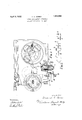
- Fig. 1 is an external view, partly in section, of a totally enclosed fuse cut-out equipped with the devices of my invention.
- Fig. 2 is a diagram of the electric equipment of a locomotive of approved design for use in the gas charged atmosphere of a coal mine.
- the battery 1 is connected with the cut-out 2 by two conductors 5 and 6 which are preferably encased in a iiexible conductor cable of the type common# ly used in coal mining apparatus, and the cutoutl 2 1s connected with ,the controller 3 and the motor 4 through the conductors 7 and 8 which are preferably a part of the permanent locomotive.
- the numeral 9 refers to an explosion proof casing within which is enclosed the cut-out and similar casings are provided for the controller 3 and the motor 4.
- conduits 10 extending from the casing 9 of the cut-out 2 to the gas tight casing of the controller 3 and the motor 4.
- These conduits 10 are preferably formed of flexible tubing suchgf15 for example as rubber and fabric hose, which is impervious to gas and affords desirable mechanical protection against abrasion of the insulation of the enclosed conductors.
- agsc coupling fitting Adjacent the end of the conduit 10 is placed agsc coupling fitting having a cylindrical sleeve 11 which closely fits the outside of the conduit, and a flange 12 which is faced to form a gas tight joint with a suitable finished surface surrounding an aperture 13 of the casing 9,535 and is securely clamped thereto b suitable machine screws.
- ther-e On the inner sur ace of the sleeve 11 ther-e are formed one or more annular ribs 14 adapted to be forced into the material of the conduit by the expansion of a-:Qo cylindrical thimble l5 which is rolled into the conduit when the parts are assembled, to securely hold the parts together and insure the joint against leakage.
- the casing aperture 1355 is bounded inwardly of the casing by a circumferential collar.
- A. projecting end 16 of the conduit extends through the aperture 13 to form a liner for the collar, this liner being designed to afford mechanical protection forg00 the insulation of the conductor, and also t0 provide additional protection against leakage between the casing and sleeve.
- connections of the conduit 8 with the casing of the controller, motor, or other elements of the apparatus may be made in the same manner as with the cut-out 2 thereby providing a complete unitary system of protection from explosion for the entire apparatus.
Landscapes
- Pipeline Systems (AREA)
Description
Apri15,1932. C, COSE-O 1,852,698
CASING FOR ELECTRIC APPARATUS Original Filed Dec. 16, 1925 WITNESSES:
@QM/@M WW Patented Apr. 5, 1932 UNITED STATES g'PA'rEN'lil OFFICE-- FREDERICK C. CosEo, on COLUMBUS, oIIIo, AssIeNoE To THE JEFFREY MANUFACTUR- ING COMPANY, or COLUMBUS, oIIIo, A CORPORATION or oHIo CASING FOR ELECTRIC APPARATUS Original application filed December 16, 1925, Serial No. l75,828. Divided and this application iiled October 19, 1928. Serial No. 313,627.
The present invention relates to certain new and useful improvements in casings for electric apparatus, and particularly to casings adapted to protect the electric equipment of locomotives, and other machinery especially designed for use in coal mines, and similar installations, from contact with the explosive gases encountered in the mine.
It is the especial object of this invention to provide eihcient and durable means for connecting the conduits through which the conductors of the circuits extend, with the explosion proof casings of the motors, controllers and the like.
The means whereby I attain this obj ect are fully set forth in the following specification and illustrated in the accompanying drawings of which Fig. 1 is an external view, partly in section, of a totally enclosed fuse cut-out equipped with the devices of my invention.
Fig. 2 is a diagram of the electric equipment of a locomotive of approved design for use in the gas charged atmosphere of a coal mine.
Like numerals refer to similar parts in both figures.
Many coal mines are so subject to accumulations of explosive gas that the use of electric apparatus therein is permissible only upon compliance with the most stringent precautions to prevent the ignition of the gaseous atmosphere by arcs formed incidental to the operation of the apparatus. To this end explosion proof casings have been devised for motors, and accessory appliances, and these casings when spaced from each other are connected by gas proof conduits through which extend the conductors of the electric locomotives.
In my co-pending application, Ser. No. 75,828, filed Dec. 16, 1925, of which this application is a division, I have shown an electric cut-out enclosed in an explosion proof case to which is connected two conduits equipped with the devices of my present invention. To facilitate the description of these devices I have provided, in Fig. 2 of the drawings, a diagrammatic illustration of the principal electric circuits of a locomotive adapted to the haulage of coal in a mine. In this diathe numeral 1 indicates a storage battery, or other suitable and convenient source of electric current supply. The numeral 2 indicates 'as an entirety a cut-out, the numeral 3a controller of the common and well known type whereby the flow of electric current may Abe regulated in the motor ,4. The battery 1 is connected with the cut-out 2 by two conductors 5 and 6 which are preferably encased in a iiexible conductor cable of the type common# ly used in coal mining apparatus, and the cutoutl 2 1s connected with ,the controller 3 and the motor 4 through the conductors 7 and 8 which are preferably a part of the permanent locomotive. In'Fig. 1 of the drawings the numeral 9 refers to an explosion proof casing within which is enclosed the cut-out and similar casings are provided for the controller 3 and the motor 4.
In order to compl-ete the gas proof endo-i610 sure of the apparat-us, I have provide conduits 10 extending from the casing 9 of the cut-out 2 to the gas tight casing of the controller 3 and the motor 4. These conduits 10 are preferably formed of flexible tubing suchgf15 for example as rubber and fabric hose, which is impervious to gas and affords desirable mechanical protection against abrasion of the insulation of the enclosed conductors. Adjacent the end of the conduit 10 is placed agsc coupling fitting having a cylindrical sleeve 11 which closely fits the outside of the conduit, and a flange 12 which is faced to form a gas tight joint with a suitable finished surface surrounding an aperture 13 of the casing 9,535 and is securely clamped thereto b suitable machine screws. On the inner sur ace of the sleeve 11 ther-e are formed one or more annular ribs 14 adapted to be forced into the material of the conduit by the expansion of a-:Qo cylindrical thimble l5 which is rolled into the conduit when the parts are assembled, to securely hold the parts together and insure the joint against leakage.
It will be noted that the casing aperture 1355 is bounded inwardly of the casing by a circumferential collar. A. projecting end 16 of the conduit extends through the aperture 13 to form a liner for the collar, this liner being designed to afford mechanical protection forg00 the insulation of the conductor, and also t0 provide additional protection against leakage between the casing and sleeve.
The connections of the conduit 8 with the casing of the controller, motor, or other elements of the apparatus, may be made in the same manner as with the cut-out 2 thereby providing a complete unitary system of protection from explosion for the entire apparatus.
What I claim is: n y i A In an apparatus of the class described, the combination with a casingv having` an aperture bounded inwardly of the casing by a cir cumferential collar, of a flexible tube, and means for securing said tube to said casing in communicating relation with the interior of the latter through said aperture, said means comprising a cylindrical sleeve closely surrounding said tubeadjacent an end thereof, a cylindrical thirnble within the tube expanded to force the walls of the latter against the inner surfaces'of said sleeve without distorting the end of the tube, and means to attach said sleeve to said casing, the end of the Vtube projecting inwardly of the casing to form a liner for said collar.
In testimony whereof I have hereunto set my' hand.
FREDERICK C. COSEO.
Priority Applications (1)
| Application Number | Priority Date | Filing Date | Title |
|---|---|---|---|
| US313627A US1852698A (en) | 1925-12-16 | 1928-10-19 | Casing for electric apparatus |
Applications Claiming Priority (2)
| Application Number | Priority Date | Filing Date | Title |
|---|---|---|---|
| US75828A US1852697A (en) | 1925-12-16 | 1925-12-16 | Cut-out |
| US313627A US1852698A (en) | 1925-12-16 | 1928-10-19 | Casing for electric apparatus |
Publications (1)
| Publication Number | Publication Date |
|---|---|
| US1852698A true US1852698A (en) | 1932-04-05 |
Family
ID=26757329
Family Applications (1)
| Application Number | Title | Priority Date | Filing Date |
|---|---|---|---|
| US313627A Expired - Lifetime US1852698A (en) | 1925-12-16 | 1928-10-19 | Casing for electric apparatus |
Country Status (1)
| Country | Link |
|---|---|
| US (1) | US1852698A (en) |
-
1928
- 1928-10-19 US US313627A patent/US1852698A/en not_active Expired - Lifetime
Similar Documents
| Publication | Publication Date | Title |
|---|---|---|
| US1890290A (en) | Fire hose coupling | |
| US2816949A (en) | Armoured cable mounting | |
| US807747A (en) | Insulating-casing for wire connections. | |
| US2209274A (en) | Insulating bushing | |
| US2309658A (en) | Packing device | |
| US3786170A (en) | Insulation gas filled encapsulated high voltage electrical conductor | |
| US1993984A (en) | Explosionproof flexible fitting | |
| US1852698A (en) | Casing for electric apparatus | |
| US2369413A (en) | Cable clamp | |
| US2712952A (en) | Means for holding together parts of machinery and joints, including such means | |
| US1565254A (en) | Pipe covering | |
| US2014288A (en) | Electrical coupling, swivel ring, and sleeve construction | |
| US1772536A (en) | of erie | |
| US2652445A (en) | Cable entrance for sealed enclosures | |
| US1947481A (en) | Cable joint | |
| US3778526A (en) | Insulation gas-filled tubular casing structure for high-voltage conductor | |
| US2076261A (en) | Electrical connecter | |
| US1097289A (en) | Cable-splice. | |
| US4255614A (en) | Method and apparatus for enclosing a cable splice | |
| US1871286A (en) | Oil seal for dynamo-electric machines | |
| US2106444A (en) | Explosionproof union | |
| US1808581A (en) | Conduit terminal | |
| US2615952A (en) | Stop for fluid filled cable systems | |
| US1829764A (en) | Conduit terminal | |
| US1725853A (en) | Conduit box |