US1852670A - Adjustable window screen - Google Patents
Adjustable window screen Download PDFInfo
- Publication number
- US1852670A US1852670A US427016A US42701630A US1852670A US 1852670 A US1852670 A US 1852670A US 427016 A US427016 A US 427016A US 42701630 A US42701630 A US 42701630A US 1852670 A US1852670 A US 1852670A
- Authority
- US
- United States
- Prior art keywords
- frame
- edges
- frames
- bars
- edge
- Prior art date
- Legal status (The legal status is an assumption and is not a legal conclusion. Google has not performed a legal analysis and makes no representation as to the accuracy of the status listed.)
- Expired - Lifetime
Links
- 239000002184 metal Substances 0.000 description 13
- 230000002093 peripheral effect Effects 0.000 description 4
- 230000003014 reinforcing effect Effects 0.000 description 4
- 210000002105 tongue Anatomy 0.000 description 3
- 238000010276 construction Methods 0.000 description 1
- 238000006073 displacement reaction Methods 0.000 description 1
- 239000000463 material Substances 0.000 description 1
- 230000002787 reinforcement Effects 0.000 description 1
Images

Classifications
-
- E—FIXED CONSTRUCTIONS
- E06—DOORS, WINDOWS, SHUTTERS, OR ROLLER BLINDS IN GENERAL; LADDERS
- E06B—FIXED OR MOVABLE CLOSURES FOR OPENINGS IN BUILDINGS, VEHICLES, FENCES OR LIKE ENCLOSURES IN GENERAL, e.g. DOORS, WINDOWS, BLINDS, GATES
- E06B9/00—Screening or protective devices for wall or similar openings, with or without operating or securing mechanisms; Closures of similar construction
- E06B9/52—Devices affording protection against insects, e.g. fly screens; Mesh windows for other purposes
- E06B9/522—Dimensionally adjustable fly screens
Definitions
- This invention relates to window screens and more particularly to that type which is made in two sections, the sections being adjustable one to another to fit a variety of '5 different width window openings.
- Another object of this invention is to provide a window screen that is rigid in design and construction and will not warp or get out of shape.
- Another object of this invention is to provide a window screen of two sections each section comprising a substantially rectangular metal frame which clamps the screen material and the upper and lower bars of the two sections interlocking in a manner to allow them to be slidably adjustable one to another.
- Another object of this invention is to provide a window screen that is adjustable for difl'erent width window openings, the vertical ends of the screen frames having flanges that project toward and in close proximity to the screen of the opposite frame to prevent bugs or flies from passing through the space between the two sections.
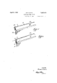
- Fig. 1 is an elevation of my improved screen.
- Fig. 2 is an enlarged horizontal section taken on line 22 of Fig. 1.
- Fig. 3 is an enlarged vertical section taken on line 38 of Fig. 1.
- Fig. 4 is a fragmentary top plan view.
- 5 is a sectional perspective view of one of the side bars of one of the frames.
- Fig. 6 is a sectionalperspective view of one of the corresponding bars of the other frame.
- the window screen comprises the two sections 1 and 2.
- the section 1 is approximately rectangular in shape and is made up of the top and bottom bars 3 and A and the end bars 5 and 6.
- the section 2 is approximately rectangular in shape and is made up of the top and bottom bars 7 and 8 and the ends bars 9 and 10.
- top and bottom bars 3 and 1- are approximately circular in cross section and are adapted to closely ene circle the reinforcing wire 11.
- the bars 3 and 4 have an. inwardly projecting flange 12 which is return bent as indicated at 13.
- the upper and lower edges of the wire mesh Ll are thus firmly gripped between the flange 12 and the return bent portion 13.
- the opposite edges of the bars 3 and 4- have an inturned flange 15. a horizontally disposed flange 16 and an outwardly projecting flange 17. This forms a U shaped guide and lock the purpose of which will be later described.
- the bars 7 and 8 are similar in design to the bars 3 and 4, are approximately circular in cross section and provided near one edge with the inturned flanges 18 and the return bent portion 19. Theupper and lower edges of the wire mesh 20 being firmly gripped therebetween.
- the opposite edge of the bars 7 and 8 have the intiirned flanges 21, the horizontally disposed flange 22 and the inwardly projecting flanges 23 which engage between the flanges 15 and 17 of the bars 3 and 4.
- Tongues 24 near the end bar 6 are punched out of the flanges 15 likewise tongues 25 near the end bar 10 are punched out of the flanges 21. These tongues 24 and 25 lie in the same horizontal plane and act as stops to limit the movement of the two sections 1 and 2 when they are expanded to their maximum width.
- the end bars 9 and 10 are likewise circular in cross section and closely encircle the reinforcing wire 27, which is similar in design to the reinforcing wire 11.
- the bars 9 and 10 are provided with inturned flanges 28 and return bent portions 29. The vertical edges of the wire mesh being held firmly between the flanges 28 and the portion 29.
- the inturned flange 30 of the bar 10 is further provided with the vertically disposed flange 31, the outer edge of which lies in close proximity to the wire mesh 1.4 of the section 1.
- the end bars 5 and 6 of the section 1 are similar in design to the bars 9 and 10 and have inturned flanges 32 and return bent portions 33.
- the vertical edges of the wire mesh 14 are held firmly between the flanges 32 and the return bentportions 33.
- the opposite edges of the bars 5 and 6 have the inturned flanges 34 and the flange 34: of the bar 6 is further provided with a vertically extending flange 35 the edge of which lies in close proximity to the wire mesh 20 of the section 2.
- the two sections 1 and 2 may be extended to their maximum width without becoming disassembled due to the stops 24 and 25 coming in contact.
- the two sections are also locked against transverse movement one to the other due to the fact that the flanges 23, of the section 2, engage between the flanges 15 and 17 of the section 1.
- the sections 1 and 2 are prevented from becoming accidentally disassembled when they are contracted to their minimum width due to the fact that the ends of the flanges 17 strike the closed ends 26 of the U shaped sections.
- An adjustable window screen comprising a pair of sheet metal frames slidably mounted in relation to each other, each frame consisting of a sheet of metal folded upon itself to provide a peripheral recess, a stiffening for each frame member in the said recess thereof, each frame member further having one of its edges folded upon itself to form a U channel, a screen member for each frame having its peripheral edges secured in the U channel, the opposite edge of each of the said frames lying over the said first edge and shaped to provide a rail complemental in form upon the respective frames providing for a sliding relationship.
- An adjustable window screen comprising a pair of sheet metal frame members of rectangular form in slidable relation one to the other, each side of each frame being formed of a metal sheet folded upon itself with the edges extending toward the enclosed space, one of said edges being bent to form a channel, a screen member having its peripheral edge clamped in place in the channels, the other edge of the opposite longitudinal portions of one of the frames being formed with an olfset lip portion, and the similar edge of the other of said frames having outwardly facing grooved portion to receive the offset lip portion of the first frame, and means limiting the extent to which the frames may be moved relatively longitudinally.
- An adjustable window screen comprising a pair of sheet metal frame members in slidable relation one to the other, the frames being of rectangular form each of the sides and ends of which is formed of a metal sheet folded upon itself with the edges extending toward the enclosed space, one of the edges of each of the side and end portions of the frame being bent upon itself to provide a screen receiving channel, a.
- each of the side portions of the frame having the opposite edge extending over the said first named edge in engagement with the screen member and having an outturned portion, the outturned portion of one frame being complemental to that of the other to provide for longitudinal sliding relationship of the two frames, one end portion of one frame and the opposite end portion of the other frame having an outturned port-ion of its edge extending to approximate contact with the screen member of the other frame for the purpose stated.
- An adjustable window screen comprising a pair of sheet metal frame members in slidable relation one to the other, each of the frames being formed of a metal sheet folded upon itself with the edges extending toward the enclosed space one of said edges being return bent and the other of said edges terminating substantially in the same plane, the said last named edge of the opposite side portions of one of the frames having a laterally outturned portion with an inturned terminal flange and the side portions of the other frame member having its terminal edge bent upon itself to form a channel opening toward the outer edge of the frame for receiving the said flange of the first frame permitting longitudinal adjustment of the two frames and preventing lateral displacement, the side portions of the frames of each frame member having lugs struck up therefrom at opposite ends of the respective frames providing abutments determining the limit of extension of the frames, the end portions at the respective opposite ends of each frame having an edge outturned to practical engagement with the screen of the respective opposite frame.
- a screen member consisting of a rectangular sheet metal frame, each of the side and end portions of which is folded upon itself, a rectangular metal reinforcing frame consisting of a rod about which the respective side and end portions of the frame are folded and providing a reinforcement for the frame, one edge of the side and end portions of the frame being returnbent upon itself, a screen member having its edges secured in place by the said return-bent portion, the other of said its edges of each of the said side and end por- I tions lying over the said channel portion of the first named edge in contact with the screen member secured thereby.
- An adjustable window screen comprising a pair of sheet metal frame members, each of the side and end portions of which are formed of a metal sheet folded upon itself with the edges extending toward the enclosed space, one of the edges of each of the side and end portions of the frame being return-bent to form a channel, a screen member for each frame, the peripheral edge of which is folded over into the said channel thereof and secured in place thereby, the other edges of the frame portions lying in contiguous relation, the two side portions of one of the frames having the terminal portion of the last named edge outwardly bent and formed with a flange and the similar contiguous edge of the other frame having its terminal portion return-bent to provide an out-facing channel to receive the flange of the first named frame portions, the opposite end portions of the two frames having the edge facing the opposite frame outwardly bent to practical contact with the screen member of the respective opposite frame, and means at opposite ends of the two frames providing an abutment limiting the distance to which the two frames may be extended.
Landscapes
- Engineering & Computer Science (AREA)
- Structural Engineering (AREA)
- Life Sciences & Earth Sciences (AREA)
- Insects & Arthropods (AREA)
- Pest Control & Pesticides (AREA)
- Architecture (AREA)
- Civil Engineering (AREA)
- Grates (AREA)
Description
l 1932- M. E. NOYES 1,852,670
ADJUSTABE WINDOW SCREEN Filed Feb. 8, 1930 2 SheetsSheet 1 Z J a 2 //5 INVENTOR.
BY Mifih Z4 22 2/ v ATTORNEY.
April 5, 1932. MOVES 1,852,650
ADJUSTABE WINDOW SCREEN Filed Feb. 8. 1,950 2 Sheets-Sheet 2 INVENTOR. /%r//h Z/Vorzs A TTORNE Y.
Patented Apr. 5, 1932 UNITED STATES PATENT 1 FFlCE ADJUSTABLE WINDOW SCREEN Application filed February 8, 1980. Serial No. 427,016.
This invention relates to window screens and more particularly to that type which is made in two sections, the sections being adjustable one to another to fit a variety of '5 different width window openings.
Another object of this invention is to provide a window screen that is rigid in design and construction and will not warp or get out of shape.
Another object of this invention is to provide a window screen of two sections each section comprising a substantially rectangular metal frame which clamps the screen material and the upper and lower bars of the two sections interlocking in a manner to allow them to be slidably adjustable one to another.
Another object of this invention is to provide a window screen that is adjustable for difl'erent width window openings, the vertical ends of the screen frames having flanges that project toward and in close proximity to the screen of the opposite frame to prevent bugs or flies from passing through the space between the two sections.
With these and other objects in view this invention comprises the principal features as described in the specification, claimed in the claims and shown in the accompanying drawings, wherein like reference characters indicate like parts throughout the several views, wherein Fig. 1 is an elevation of my improved screen.
Fig. 2 is an enlarged horizontal section taken on line 22 of Fig. 1.
Fig. 3 is an enlarged vertical section taken on line 38 of Fig. 1.
Fig. 4 is a fragmentary top plan view.
5 is a sectional perspective view of one of the side bars of one of the frames.
Fig. 6 is a sectionalperspective view of one of the corresponding bars of the other frame.
The window screen comprises the two sections 1 and 2. The section 1 is approximately rectangular in shape and is made up of the top and bottom bars 3 and A and the end bars 5 and 6. Likewise the section 2 is approximately rectangular in shape and is made up of the top and bottom bars 7 and 8 and the ends bars 9 and 10.
As best seen in Fig. 3 the top and bottom bars 3 and 1- are approximately circular in cross section and are adapted to closely ene circle the reinforcing wire 11. The bars 3 and 4 have an. inwardly projecting flange 12 which is return bent as indicated at 13. The upper and lower edges of the wire mesh Ll are thus firmly gripped between the flange 12 and the return bent portion 13.
The opposite edges of the bars 3 and 4- have an inturned flange 15. a horizontally disposed flange 16 and an outwardly projecting flange 17. This forms a U shaped guide and lock the purpose of which will be later described. The bars 7 and 8 are similar in design to the bars 3 and 4, are approximately circular in cross section and provided near one edge with the inturned flanges 18 and the return bent portion 19. Theupper and lower edges of the wire mesh 20 being firmly gripped therebetween.
The opposite edge of the bars 7 and 8 have the intiirned flanges 21, the horizontally disposed flange 22 and the inwardly projecting flanges 23 which engage between the flanges 15 and 17 of the bars 3 and 4.
Tongues 24: near the end bar 6 are punched out of the flanges 15 likewise tongues 25 near the end bar 10 are punched out of the flanges 21. These tongues 24 and 25 lie in the same horizontal plane and act as stops to limit the movement of the two sections 1 and 2 when they are expanded to their maximum width.
As best seen in Fig. 2 the ends 26 of the flanges 17 are bent in against the flanges 15, after the sections 1 and 2 are assembled to prevent said section from becoming accidentally disassembled.
The end bars 9 and 10 are likewise circular in cross section and closely encircle the reinforcing wire 27, which is similar in design to the reinforcing wire 11. The bars 9 and 10 are provided with inturned flanges 28 and return bent portions 29. The vertical edges of the wire mesh being held firmly between the flanges 28 and the portion 29.
The opposite edges of the bars 9 and 10 are provided with the inturned flanges 30, and
the inturned flange 30 of the bar 10 is further provided with the vertically disposed flange 31, the outer edge of which lies in close proximity to the wire mesh 1.4 of the section 1.
The end bars 5 and 6 of the section 1 are similar in design to the bars 9 and 10 and have inturned flanges 32 and return bent portions 33. The vertical edges of the wire mesh 14 are held firmly between the flanges 32 and the return bentportions 33.
The opposite edges of the bars 5 and 6 have the inturned flanges 34 and the flange 34: of the bar 6 is further provided with a vertically extending flange 35 the edge of which lies in close proximity to the wire mesh 20 of the section 2.
It will thus be seen that the two sections 1 and 2 may be extended to their maximum width without becoming disassembled due to the stops 24 and 25 coming in contact. The two sections are also locked against transverse movement one to the other due to the fact that the flanges 23, of the section 2, engage between the flanges 15 and 17 of the section 1. The sections 1 and 2 are prevented from becoming accidentally disassembled when they are contracted to their minimum width due to the fact that the ends of the flanges 17 strike the closed ends 26 of the U shaped sections.
Having thus fully described my invention, its utility and mode of operation, what I claim and desire to secure by Letters Patent of the United States is 1. An adjustable window screen comprising a pair of sheet metal frames slidably mounted in relation to each other, each frame consisting of a sheet of metal folded upon itself to provide a peripheral recess, a stiffening for each frame member in the said recess thereof, each frame member further having one of its edges folded upon itself to form a U channel, a screen member for each frame having its peripheral edges secured in the U channel, the opposite edge of each of the said frames lying over the said first edge and shaped to provide a rail complemental in form upon the respective frames providing for a sliding relationship.
2. An adjustable window screen comprising a pair of sheet metal frame members of rectangular form in slidable relation one to the other, each side of each frame being formed of a metal sheet folded upon itself with the edges extending toward the enclosed space, one of said edges being bent to form a channel, a screen member having its peripheral edge clamped in place in the channels, the other edge of the opposite longitudinal portions of one of the frames being formed with an olfset lip portion, and the similar edge of the other of said frames having outwardly facing grooved portion to receive the offset lip portion of the first frame, and means limiting the extent to which the frames may be moved relatively longitudinally.
3. An adjustable window screen comprising a pair of sheet metal frame members in slidable relation one to the other, the frames being of rectangular form each of the sides and ends of which is formed of a metal sheet folded upon itself with the edges extending toward the enclosed space, one of the edges of each of the side and end portions of the frame being bent upon itself to provide a screen receiving channel, a. screen member having its edges inturned therein and held in place thereby, each of the side portions of the frame having the opposite edge extending over the said first named edge in engagement with the screen member and having an outturned portion, the outturned portion of one frame being complemental to that of the other to provide for longitudinal sliding relationship of the two frames, one end portion of one frame and the opposite end portion of the other frame having an outturned port-ion of its edge extending to approximate contact with the screen member of the other frame for the purpose stated.
4. An adjustable window screen comprising a pair of sheet metal frame members in slidable relation one to the other, each of the frames being formed of a metal sheet folded upon itself with the edges extending toward the enclosed space one of said edges being return bent and the other of said edges terminating substantially in the same plane, the said last named edge of the opposite side portions of one of the frames having a laterally outturned portion with an inturned terminal flange and the side portions of the other frame member having its terminal edge bent upon itself to form a channel opening toward the outer edge of the frame for receiving the said flange of the first frame permitting longitudinal adjustment of the two frames and preventing lateral displacement, the side portions of the frames of each frame member having lugs struck up therefrom at opposite ends of the respective frames providing abutments determining the limit of extension of the frames, the end portions at the respective opposite ends of each frame having an edge outturned to practical engagement with the screen of the respective opposite frame.
5. A screen member consisting of a rectangular sheet metal frame, each of the side and end portions of which is folded upon itself, a rectangular metal reinforcing frame consisting of a rod about which the respective side and end portions of the frame are folded and providing a reinforcement for the frame, one edge of the side and end portions of the frame being returnbent upon itself, a screen member having its edges secured in place by the said return-bent portion, the other of said its edges of each of the said side and end por- I tions lying over the said channel portion of the first named edge in contact with the screen member secured thereby.
6. An adjustable window screen comprising a pair of sheet metal frame members, each of the side and end portions of which are formed of a metal sheet folded upon itself with the edges extending toward the enclosed space, one of the edges of each of the side and end portions of the frame being return-bent to form a channel, a screen member for each frame, the peripheral edge of which is folded over into the said channel thereof and secured in place thereby, the other edges of the frame portions lying in contiguous relation, the two side portions of one of the frames having the terminal portion of the last named edge outwardly bent and formed with a flange and the similar contiguous edge of the other frame having its terminal portion return-bent to provide an out-facing channel to receive the flange of the first named frame portions, the opposite end portions of the two frames having the edge facing the opposite frame outwardly bent to practical contact with the screen member of the respective opposite frame, and means at opposite ends of the two frames providing an abutment limiting the distance to which the two frames may be extended.
In testimony whereof, I sign this specification.
MAYHEW E. NOYES.
Priority Applications (1)
| Application Number | Priority Date | Filing Date | Title |
|---|---|---|---|
| US427016A US1852670A (en) | 1930-02-08 | 1930-02-08 | Adjustable window screen |
Applications Claiming Priority (1)
| Application Number | Priority Date | Filing Date | Title |
|---|---|---|---|
| US427016A US1852670A (en) | 1930-02-08 | 1930-02-08 | Adjustable window screen |
Publications (1)
| Publication Number | Publication Date |
|---|---|
| US1852670A true US1852670A (en) | 1932-04-05 |
Family
ID=23693135
Family Applications (1)
| Application Number | Title | Priority Date | Filing Date |
|---|---|---|---|
| US427016A Expired - Lifetime US1852670A (en) | 1930-02-08 | 1930-02-08 | Adjustable window screen |
Country Status (1)
| Country | Link |
|---|---|
| US (1) | US1852670A (en) |
-
1930
- 1930-02-08 US US427016A patent/US1852670A/en not_active Expired - Lifetime
Similar Documents
| Publication | Publication Date | Title |
|---|---|---|
| US2233412A (en) | Metallic window screen | |
| US1852866A (en) | Corner brace for window screens | |
| US1612261A (en) | Window screen | |
| US2742679A (en) | Spring loaded pressure clip for storm shutters | |
| US1852670A (en) | Adjustable window screen | |
| US2207381A (en) | Metallic window screen | |
| US1775717A (en) | Screen-frame construction | |
| US1674619A (en) | Curtain fixture | |
| US1344110A (en) | Hanger | |
| US2225167A (en) | Constant height adjustable grille | |
| US1496594A (en) | Metallic screen | |
| US2519998A (en) | Frameless window screen | |
| US1646049A (en) | Curtain rod | |
| US1507477A (en) | Adjustable window screen | |
| US1299016A (en) | Adjustable window-screen. | |
| US1583972A (en) | Metal-frame screen | |
| US1740960A (en) | Window-screen fixture | |
| DE102014009422A1 (en) | Clamping element for clamping a flat, flexible material and weighting element and gripping element and panel carriage | |
| US1281006A (en) | Window-shade. | |
| US1470658A (en) | Window screen | |
| US1599446A (en) | Filing-case construction | |
| US683307A (en) | Adjustable screen. | |
| US1084761A (en) | Folding shade. | |
| US1869786A (en) | Window screen and support therefor | |
| US1622598A (en) | Hinge support |