US1852643A - Fuel pump - Google Patents
Fuel pump Download PDFInfo
- Publication number
- US1852643A US1852643A US445158A US44515830A US1852643A US 1852643 A US1852643 A US 1852643A US 445158 A US445158 A US 445158A US 44515830 A US44515830 A US 44515830A US 1852643 A US1852643 A US 1852643A
- Authority
- US
- United States
- Prior art keywords
- chamber
- diaphragm
- fuel
- pressure
- valve
- Prior art date
- Legal status (The legal status is an assumption and is not a legal conclusion. Google has not performed a legal analysis and makes no representation as to the accuracy of the status listed.)
- Expired - Lifetime
Links
- 239000000446 fuel Substances 0.000 title description 39
- 238000005086 pumping Methods 0.000 description 24
- 239000013049 sediment Substances 0.000 description 11
- 230000001050 lubricating effect Effects 0.000 description 10
- 239000007788 liquid Substances 0.000 description 7
- 210000003811 finger Anatomy 0.000 description 4
- 238000002485 combustion reaction Methods 0.000 description 3
- 230000001419 dependent effect Effects 0.000 description 3
- 239000012530 fluid Substances 0.000 description 3
- 230000000717 retained effect Effects 0.000 description 3
- 238000004891 communication Methods 0.000 description 2
- 238000012423 maintenance Methods 0.000 description 2
- 230000037452 priming Effects 0.000 description 2
- OHYPPUOVSUINHM-UHFFFAOYSA-N 4-(methylamino)phenol;sulfuric acid Chemical compound OS(O)(=O)=O.CNC1=CC=C(O)C=C1 OHYPPUOVSUINHM-UHFFFAOYSA-N 0.000 description 1
- 101100168115 Neurospora crassa (strain ATCC 24698 / 74-OR23-1A / CBS 708.71 / DSM 1257 / FGSC 987) con-6 gene Proteins 0.000 description 1
- 230000004075 alteration Effects 0.000 description 1
- 230000000295 complement effect Effects 0.000 description 1
- 230000006835 compression Effects 0.000 description 1
- 238000007906 compression Methods 0.000 description 1
- 230000000694 effects Effects 0.000 description 1
- 239000000463 material Substances 0.000 description 1
- 230000000737 periodic effect Effects 0.000 description 1
- 238000007789 sealing Methods 0.000 description 1
- 210000003813 thumb Anatomy 0.000 description 1
Images
Classifications
-
- F—MECHANICAL ENGINEERING; LIGHTING; HEATING; WEAPONS; BLASTING
- F02—COMBUSTION ENGINES; HOT-GAS OR COMBUSTION-PRODUCT ENGINE PLANTS
- F02M—SUPPLYING COMBUSTION ENGINES IN GENERAL WITH COMBUSTIBLE MIXTURES OR CONSTITUENTS THEREOF
- F02M1/00—Carburettors with means for facilitating engine's starting or its idling below operational temperatures
-
- F—MECHANICAL ENGINEERING; LIGHTING; HEATING; WEAPONS; BLASTING
- F02—COMBUSTION ENGINES; HOT-GAS OR COMBUSTION-PRODUCT ENGINE PLANTS
- F02M—SUPPLYING COMBUSTION ENGINES IN GENERAL WITH COMBUSTIBLE MIXTURES OR CONSTITUENTS THEREOF
- F02M2700/00—Supplying, feeding or preparing air, fuel, fuel air mixtures or auxiliary fluids for a combustion engine; Use of exhaust gas; Compressors for piston engines
- F02M2700/43—Arrangements for supplying air, fuel or auxiliary fluids to a combustion space of mixture compressing engines working with liquid fuel
- F02M2700/4302—Arrangements for supplying air, fuel or auxiliary fluids to a combustion space of mixture compressing engines working with liquid fuel whereby air and fuel are sucked into the mixture conduit
- F02M2700/438—Supply of liquid to a carburettor reservoir with limitation of the liquid level; Aerating devices; Mounting of fuel filters
- F02M2700/4388—Supply of liquid to a carburettor reservoir with limitation of the liquid level; Aerating devices; Mounting of fuel filters with fuel displacement by a pump
- F02M2700/439—Supply of liquid to a carburettor reservoir with limitation of the liquid level; Aerating devices; Mounting of fuel filters with fuel displacement by a pump the pump being a membrane pump
Definitions
- 'Ihis invention relates to fuel pumps, and' has for an object the provision of a novel't 'of fuel pump, the operation of which is ependent upon the maintenance of a prede- 5 termined pressure in the lubricating system of the engine with which the fuel pump is associated, thereby insuring cessation of the' operation ofthe engine should failure of the oil pressure occur throughany cause.
- l5 -Anothersobject is to rovide a fuel ump in which the-pumping e ement is in t e form of a diaphragm having means associated therewith for reciprocating the center portion thereof, with respect to' the plane of i' 2o its periphery, and in which the reciprocating means are so arranged that the reciprocation lof the center portion of the diaphragm extends to'equal distances upon oppositesides of that plane.
- a further object is to providey positive means for. easily determining the development ⁇ of any leak in the reciprocable, diaphragm. )e
- This invention possesses other objects and 30 advantageous features, some of which, with those enumerated, will be set forth .in the following description of the inventions particular embodiment which is illustrated in the drawings accompanying and forming apart 35' of the specification.
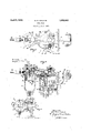
- Figure 1 is atop plan view of a fuel pump i embodying the principles of the present in vention. 4o
- Fig. 3 is a horizontal that portionof the housin which contains the pumping mechanism.. he plane of sece tion isjindicated by the line a-3 of Fig. 2,
- the fuel pumpof the present invention isl 5 -3 'designed primarily for use ⁇ in conjunction with an internal combustion. motor such as i that commonly employed'. for the propulsion by a plurality of cap screws 7, to any con- 6, into the interior of the motor base, an
- a short arm 19 of the Fig. 2 is a longitudinal, vertical, medial sectionall view of of anautomtive vehicle. II wish it to be un.
- the preferre em odiment of my improved fuel pump comprises a housing 6 adapted to be secured in any Aconvenient manner such as venient portion of the base 8 of the motor with which the fuel pump is associated.
- 'A preferably circular boss 9 n a side of the housing 6, is adapted to seat within a 'complementary recess 11 in the motor base 8, so ⁇ as to hold an aperture 12 in that side of the housing 6 in register with an aperture 13 in the motor'base,'so as to permit a rocker arm 14 to extend from the interior of the housing establish suitable connection with a cam 16 70 which is carried by a cam shaft 17 or any other' suitable cyclically-moving part of the motol, so as to effect periodic reciprocation of the rocker arm 14.
- the rocker arm 14 is pivotally mounted upon a preferably horizontally 'extendin stub shaft 18 which extendstransversely 0% the aperture 12, and which is preferably rigid rocker arm I4, extends beyond the stub shaftA 18 and ,carries a transversely extending bar 21 and a finger 22 extending downwards to be engaged by a lcap or 'ferrule 23 which is continually urged upwards by means of a coil sprin 24 which is retained in axial alignment with t e finger 22, by means of a central boss 26 rigid with the bottom 27'of the housing 6. Due to the presence of this spring 24, the finger 22 and arm 19I of the rocker arm 14, are continually urged upwards; with the result that-the opposite end 28 of the rocker arm 14, is at all times maintained in riding contact with the cam 16. 1
- crank arm 31 Also pivotally mounted upon the stub aft 18, is a crank arm 31. That end 32 fof the crank rm 31, which is pivoted upon the shaft 18, is bufurcated (see Fig. 3) and the -only connection between the crank arm 31 and the rocker arm 14, is through the exsurface of the bifurcated end 32 of the crank arm 31.
- movement of the bar 21 downwards causes corresponding downward pivotal movement of'the crank arm 31; but upward retraction of the bar 21 does not cause the return stroke of the crank arm 31.
- upward movement of the crank arm 3l is dependent upon a coil spring 33 which is interposed between a cap or ferrule 34 and the upper side of a piston 36.
- the cap 34 engages a finger 37 at the bottom end of a reciprocably mounted rod 38 to which the outer end of the crank arm 31 is joined.
- a reciprocably mounted rod 38 to which the outer end of the crank arm 31 is joined.
- Any convenient means may be employed' for joining the crank arm 31 to the rod 38-for example, the outer end 39 of the crank arm 31 may also be bifurcated t'o engage upon opposite sides of the rod 38 and to permit a pin 41 to extend through the bifurcated end 39 and through a .suitable aperture in the rod 38.
- a suitable conduit 47 leads from the inlet 48 of the chamber 46, to 'the pressure lubricating system of the engine with which the pump is associated; and the partsare so .proportioned and arranged that the piston 36 is adapted to be forced upwards by oil 49 within the chamber 46 when the pressure of the oil in the lubricating system is maintained at a predetermined value.
- Upward movement of the piston 36 is limited by means of a ferrule 51 threaded onto the upper end o'f an annular extension 52 of the side walls of the pressure chamber 46.
- I prefer to employ some suitable type of sealing means such as a piston ring 53 to establish a substantially leak-proof seal between the piston 36 and the boreof the chamber Y46, al-
- a diaphragm 59 eX- f tends transversely of the chamber' 58, being retained in operative position by having the periphery thereof,"compressed between the head 56 and the upper end of the chamber 6;
- the center portion of the diaphragm 59 is engaged between opposed plates 61 and 62 which are rigidly connected with the upper end of the rod 38 through the expedient of a nut 63 or its equivalent.
- reciprocation of the rod 38 produces corresponding reciprocation of the center portion of. the diaphragm 59; and in order to provide guiding means for the reciprocation of these parts, the rod 38 is slidably retained within a cylindrical guide 64 extending downwards from the top of the housin 6.
- a bleeder hole 66 establishes communication between the exterior of the housing 6 and the chamber 58 below the diaphragm 59.
- the outlet from the pump chamber 58 is by way of a conduit 67 which leads to the carburetor of the engine, or to whatever means for utilizing fuel are employed.
- This conduit 67 is connected by means of a conventional union fitting 68, to a valve chamber 69 above a valve plate 71 which is pressed downward upo'n its seat 72, by means of a spring 73 which is under com ression between the valve plate 71 and a p ug 74 which is threaded into the upper end of the valve chamber 69.
- Below the valve plate 71 the valve chamber 69 enters the pump chamber 58 above the diaphragm 59, i. e., upon the opposite side thereof from that with which the bleeder hole 66 communicates.
- a lateral extension 76 of the head 56 supports a supply reservoir 77 which preferably serves as a sediment trap.
- a bail 78 pivotally joined to the extension 76 extends around the b ottom end of the trap 77 and carries a threaded pin 79 upon which a thumb nut 81 is threaded. This nut 81 may be screwed upwards against the bottom of the trap 77, to press the trap upwards against a gasket 82 to establish a tight seal between the upper end of the trap 77 and the under face of the extension 76 of the head 56.
- Communication is established between the trap 77 and the pump chamber 58 through the expedient of a passage 83 and a second valve chamber 84.
- the passage 83 enters the chamber 84 above a valve plate 86 which is pressed downwards against its seat 87 by means of a spring 88 which is under compression between the valve plate 86 and a valve plug 89 which is threaded into the upper end of the valve chamber 84.
- a draught-tube 91 is threaded into the valve seat 87, this draught-tube 91 extending downwards into the trap 77 and preferably being provided at its lower end, with a strainer 92.
- the inlet to the sediment trap 77 is by way of a conduit 96 which leads from the asoline-tank or whatever source of liquid uel is employed, and isconnected to the extension 76 of the head 56, by means of a "v107, tovertical movement; and a stop conventional union fitting 97.
- the entrance 98 of the fitting 97 into the extension76 communicates with the interior/of the tra '77v preferably by means of a tube 99 whic Aextends downwards therefroml a'. material distance into the trap 77.
- a needle valve 107 is associated with the valve seat4 104, and is rigidly connected to a float 108 which is disposed inside thetra 77 adjal which in one directionis caused by the downward movement of the arm 31coincident with rotation of the cam l'againstthe-end 28 of the rocker arm 14,' an'd the return stroke of which is caused -by the spring 33, causes the center portion of the diaphragm 5'9'to move- -the same distance above the plane of the periphery of the diaphragm .upon the upstroke,
- a pumping member operable by reciprocation thereof, means for periodically moving said pumping member in one direction, a pressure chamber adapted to receive Huid under ressure, a wall of said chamber being movable and responsive to variation of pressure therebehind, and rneans supported on said movable wall for moving said member in the other direction.
- a pumping member operable by reciprocation thereof, a pressure chamber, means connecting said chamber to a pressure lubricating system, a will of said chamber being movable with respect to the remainder of said chamber and responsive to pressure changes-therein, spring means interposed between said movable wall and said pumping member for moving the pumping member in one direction, and means for periodically withdrawing said pumping mem- .ber against they action ofsaid spring means.
- a housing having a chamber, a diaphragm extendmg thereacross, valved inlet and outlet passages communicating with said chamber on one side of said dia hragm, a rod rigid with said diaphragm, sai housing having a pressure chamber therein, means connecting said pressure chamber to a source of fluid under ⁇ pressure, a piston reciprocable within said pressure chamber,I a s ring interposed between said piston and sai rod, and means for periodically movgsaid rod against the action of said spring.
- a housing having a chamber, a diaphragm extending thereacross, valved inlet and' outlet passages communieating with said chamber'on one side of said iaphragm, and means for reciprocati tion perpendicular to the normal plane therethe center portion of said diaphragm in a lrecof, the stroke of said center portion extending y vto equal distances upon the opposite sides of the plane of the periphery of the diaphragm.
- a housing having a chamber, a diaphragm extending thereacross, valved inlet Aand outlet passages communieating with said'chamber onone'side of said diaphragm, and means for reciprocating the center portion of said diaphragm, said housing having a bleeder holepextending from the exterior thereof to said chamber on the other side of said diaphragm.
- a fuel pump pumping means, a sediment trap, a passage leading from said sediment tra to said pumping means, a conduit leading rom said trap to a source of liquid fuel, and means for automatically priming said sediment trap to draw suicient fuel thereinto to fill the trap abovethe level of the entrance thereinto of said passage.
- valve associated therewith, a float connected to said valve and adapted-to close the valve when the level of the fuel within said trap reaches a predetermined height, and a con I A duit leading from said valve seat to an area of relatively low pressure.
- a pumping member operable by reciprocation thereof, means for periodically moving said member in one di- 15 rection, 'a pressure chamber adapted to receive fluid under pressuretand means operated by ressure within said chamber for moving sai lpumping means in the other direction.
- a pumping member op ⁇ erable by reciprocation thereof, vmeans for periodically moving said member in one di- A rection, a pressure chamber adapted to rep ceive fluid under pressure, means operated by pressure within id chamber formoving said pumpinganeansi the other direction, and re-v silient means interposed between said pressure-operated means and said pumpingmem-v ber' to permit movement of saidl pumping 39 member by said periodically moving means 'against the action of said pressure-operated means.- ⁇ je i3.
- an internal com ⁇ bustionv engine having an ⁇ intake manifold, a carburetor, and a fuel supply conduit, pump- 'f ing means, a supply reservoir ,communicating with said pumpin means and vwith said conduit, a valve seat 1n the to of Asaid “reservoir, a valve associated therewit ,a iioat connected 40 to said valve and adapted to close the valve v when the -level of the fuel within said reservoir reaches a predetermined height, and a conduit leading'from said valve seat to said manifold.
Landscapes
- Engineering & Computer Science (AREA)
- Chemical & Material Sciences (AREA)
- Combustion & Propulsion (AREA)
- Mechanical Engineering (AREA)
- General Engineering & Computer Science (AREA)
- Reciprocating Pumps (AREA)
Description
April 5 1932- o. o. COLLINS 1,852,643
FUEL PUMP Filed April 17'. 1930 Pleated .ap-r. s, 1932 onu: osoN COLLINS, or mvnnsmn, oamromvra,
' rum. Pour Application med April 17, 1930. Serial No. 445,158.l
'Ihis invention relates to fuel pumps, and' has for an object the provision of a novel't 'of fuel pump, the operation of which is ependent upon the maintenance of a prede- 5 termined pressure in the lubricating system of the engine with which the fuel pump is associated, thereby insuring cessation of the' operation ofthe engine should failure of the oil pressure occur throughany cause.
Another objectis to provide simple and efficient means for automaticall and quickly priming the pump in the event t at the source of supply thereto has been permitted to 'become dry., l5 -Anothersobject is to rovide a fuel ump in which the-pumping e ement is in t e form of a diaphragm having means associated therewith for reciprocating the center portion thereof, with respect to' the plane of i' 2o its periphery, and in which the reciprocating means are so arranged that the reciprocation lof the center portion of the diaphragm extends to'equal distances upon oppositesides of that plane. n
25 A further object is to providey positive means for. easily determining the development `of any leak in the reciprocable, diaphragm. )e This invention possesses other objects and 30 advantageous features, some of which, with those enumerated, will be set forth .in the following description of the inventions particular embodiment which is illustrated in the drawings accompanying and forming apart 35' of the specification.
Referring to the drawings: Figure 1 is atop plan view of a fuel pump i embodying the principles of the present in vention. 4o
r sectional view.I
Fig. 3 is a horizontal that portionof the housin which contains the pumping mechanism.. he plane of sece tion isjindicated by the line a-3 of Fig. 2,
:indthedirection of view by the arrows.
Y The fuel pumpof the present invention, isl 5 -3 'designed primarily for use `in conjunction with an internal combustion. motor such as i that commonly employed'. for the propulsion by a plurality of cap screws 7, to any con- 6, into the interior of the motor base, an
with the housing 6. A short arm 19 of the Fig. 2 is a longitudinal, vertical, medial sectionall view of of anautomtive vehicle. II wish it to be un.
of supplying fuel to substantially any type of engme usin li uid fuel.
The preferre em odiment of my improved fuel pump, comprises a housing 6 adapted to be secured in any Aconvenient manner such as venient portion of the base 8 of the motor with which the fuel pump is associated. 'A preferably circular boss 9 n a side of the housing 6, is adapted to seat within a 'complementary recess 11 in the motor base 8, so` as to hold an aperture 12 in that side of the housing 6 in register with an aperture 13 in the motor'base,'so as to permit a rocker arm 14 to extend from the interior of the housing establish suitable connection with a cam 16 70 which is carried by a cam shaft 17 or any other' suitable cyclically-moving part of the motol, so as to effect periodic reciprocation of the rocker arm 14.
The rocker arm 14 is pivotally mounted upon a preferably horizontally 'extendin stub shaft 18 which extendstransversely 0% the aperture 12, and which is preferably rigid rocker arm I4, extends beyond the stub shaftA 18 and ,carries a transversely extending bar 21 and a finger 22 extending downwards to be engaged by a lcap or 'ferrule 23 which is continually urged upwards by means of a coil sprin 24 which is retained in axial alignment with t e finger 22, by means of a central boss 26 rigid with the bottom 27'of the housing 6. Due to the presence of this spring 24, the finger 22 and arm 19I of the rocker arm 14, are continually urged upwards; with the result that-the opposite end 28 of the rocker arm 14, is at all times maintained in riding contact with the cam 16. 1
Also pivotally mounted upon the stub aft 18, is a crank arm 31. That end 32 fof the crank rm 31, which is pivoted upon the shaft 18, is bufurcated (see Fig. 3) and the -only connection between the crank arm 31 and the rocker arm 14, is through the exsurface of the bifurcated end 32 of the crank arm 31. Hence, movement of the bar 21 downwards, causes corresponding downward pivotal movement of'the crank arm 31; but upward retraction of the bar 21 does not cause the return stroke of the crank arm 31. Instead, upward movement of the crank arm 3l is dependent upon a coil spring 33 which is interposed between a cap or ferrule 34 and the upper side of a piston 36. The cap 34 engages a finger 37 at the bottom end of a reciprocably mounted rod 38 to which the outer end of the crank arm 31 is joined. Any convenient means may be employed' for joining the crank arm 31 to the rod 38-for example, the outer end 39 of the crank arm 31 may also be bifurcated t'o engage upon opposite sides of the rod 38 and to permit a pin 41 to extend through the bifurcated end 39 and through a .suitable aperture in the rod 38. In view of the rotary motion of the crank arm 31 during reciprocation thereof, it will be necessary when such connecting means are employed, tdenlarge laterally the aperture in the rod 38 and/0r the apertures in the bifurcated end' 39 of the crank arm 31, to permit that amount of lateral movement of the end 39 of the crank arm 31 with respect to the rod 38 which is coincident with the reciprocation of these two elements.
The piston- 36 upon which the spring 33 is supported, forms the upper wall of a pressure chamber 46 which is formed in the bottom 27 of the housing 6. A suitable conduit 47 leads from the inlet 48 of the chamber 46, to 'the pressure lubricating system of the engine with which the pump is associated; and the partsare so .proportioned and arranged that the piston 36 is adapted to be forced upwards by oil 49 within the chamber 46 when the pressure of the oil in the lubricating system is maintained at a predetermined value. Upward movement of the piston 36 is limited by means of a ferrule 51 threaded onto the upper end o'f an annular extension 52 of the side walls of the pressure chamber 46. I prefer to employ some suitable type of sealing means such as a piston ring 53 to establish a substantially leak-proof seal between the piston 36 and the boreof the chamber Y46, al-
' though no serious consequences will resultfroma limited amount of leakage of oil from the chamber 46 into the interior of the housing 6 of the pump, inasmuch as any oil which chamber 58 is formed. A diaphragm 59 eX- f tends transversely of the chamber' 58, being retained in operative position by having the periphery thereof,"compressed between the head 56 and the upper end of the chamber 6; The center portion of the diaphragm 59 is engaged between opposed plates 61 and 62 which are rigidly connected with the upper end of the rod 38 through the expedient of a nut 63 or its equivalent. Hence, reciprocation of the rod 38 produces corresponding reciprocation of the center portion of. the diaphragm 59; and in order to provide guiding means for the reciprocation of these parts, the rod 38 is slidably retained within a cylindrical guide 64 extending downwards from the top of the housin 6.
A bleeder hole 66 establishes communication between the exterior of the housing 6 and the chamber 58 below the diaphragm 59.
The outlet from the pump chamber 58 is by way of a conduit 67 which leads to the carburetor of the engine, or to whatever means for utilizing fuel are employed. This conduit 67 is connected by means of a conventional union fitting 68, to a valve chamber 69 above a valve plate 71 which is pressed downward upo'n its seat 72, by means of a spring 73 which is under com ression between the valve plate 71 and a p ug 74 which is threaded into the upper end of the valve chamber 69. Below the valve plate 71 the valve chamber 69 enters the pump chamber 58 above the diaphragm 59, i. e., upon the opposite side thereof from that with which the bleeder hole 66 communicates.
A lateral extension 76 of the head 56, supports a supply reservoir 77 which preferably serves as a sediment trap. A bail 78 pivotally joined to the extension 76, extends around the b ottom end of the trap 77 and carries a threaded pin 79 upon which a thumb nut 81 is threaded. This nut 81 may be screwed upwards against the bottom of the trap 77, to press the trap upwards against a gasket 82 to establish a tight seal between the upper end of the trap 77 and the under face of the extension 76 of the head 56.
Communication is established between the trap 77 and the pump chamber 58 through the expedient of a passage 83 and a second valve chamber 84. The passage 83 enters the chamber 84 above a valve plate 86 which is pressed downwards against its seat 87 by means of a spring 88 which is under compression between the valve plate 86 and a valve plug 89 which is threaded into the upper end of the valve chamber 84. Below the valve plate 86 a draught-tube 91 is threaded into the valve seat 87, this draught-tube 91 extending downwards into the trap 77 and preferably being provided at its lower end, with a strainer 92.
The inlet to the sediment trap 77 is by way of a conduit 96 which leads from the asoline-tank or whatever source of liquid uel is employed, and isconnected to the extension 76 of the head 56, by means of a "v107, tovertical movement; and a stop conventional union fitting 97. The entrance 98 of the fitting 97 into the extension76, communicates with the interior/of the tra '77v preferably by means of a tube 99 whic Aextends downwards therefroml a'. material distance into the trap 77. l i
. Means afre also provided for pri1ning`the fuel ump. A conduit 101 leading from any suifta le area of relatively low pressure, such for example, as the intake manifold of the engine with which the fuel pump-is asso-A ciated, is connected by means of a union fitting 102 to a passage 103' in the extension. 76. This passage 103'communi'ca-tes with a preferably removable valve seat 104 having a-relatively small aperture 106 extending therethrough into the passage 103. A needle valve 107 is associated with the valve seat4 104, and is rigidly connected to a float 108 which is disposed inside thetra 77 adjal which in one directionis caused by the downward movement of the arm 31coincident with rotation of the cam l'againstthe-end 28 of the rocker arm 14,' an'd the return stroke of which is caused -by the spring 33, causes the center portion of the diaphragm 5'9'to move- -the same distance above the plane of the periphery of the diaphragm .upon the upstroke,
f as the distance below that plane which this portion'ofthe diaphragm moves upon the `ldownstroke thereof. In' this manner, the
maximum stroke of thev centerportion of the diaphragm, is vattained with .a minimum amount of distortion thereof from trueplanar arrangement, as compared with the more usual manner of utilizing a diaphragm' pumping member whereinthe` diaphragm at one end of its stroke, lies substantially flat` and at the Aother end of its stroke 'is distorted v to permit the center portion of the diaphragm the bottom ofl itsl stroke, whereasthe dashed tially r theupperfextreme of its stro to lie in a plane spaced from the plane of the periphery, a distance equal to the maximum stroke. The full line position ofthe diaphra 59 upon Fig. 2, indicates the position of t ediaphragm when at substantlally line position indicated at 59', show'ssubstanthe position of the dia hragm when at Operation I' I Y. Iif, for lanjy'vreasonyth-e sediment .trap 77 filled or primed as soon* as the crankshaft -of the engine starts to turn, because of the vacuum developed in the intake manifold by the pumping action ofy the pistons of that engine.- Inasmuch as the conduit 101'communicates with the intake manifold or some f other part of the :mechanism wherein an area of low pressure exists, under such circumstances, air .will be drawn past the needle v valve 107 and through the conduit 101. However, the only inlet to the sediment trap 77, is through the conduit'96 which leads from the gasoline-tank because the spring- 'pressed valve plate 86r precludes the possibil- 1;1ty of entrance into the sediment trap 77 by way of the passage 83. `Accordingl gasoline or 'whatever liquid -fuel is beii'igemlployed, will be drawn through-the conduit 96 and into the sediment trap 77. This flow of' fuel intothe trap 77 will continue, provided rotation of the crankshaft is continued, until A the level of the liquid within the trap 77 has reachedthat height which results in floating the float 108 suiiiciently to bring the valve 107 into seatingengagement with the valve seat V 104. This is the normal position of the valve 107 and float 108, it being understood that these parts become displaced\fro1n this position only when the liquid within the trap 77 has fallen below a predetermined level.
In this manner, a sucient quantity of liquid fuel is automaticallymaintained within the trap 77, so. that the lower end of the vdraught-tube'91, is immersed therein. Con-v sequently, the downstroke ofthe diaphragm"l 59, will cause "a givcnquantity of this fue] to be drawn past the check valve 86, through.
the passage 83, and into that\p or tion ofthe'. f
pump chamber 58 which isabove the dia- 59. As soon as the downstroke of?l the diaphragm ceases, the check valve 86 will;` be seated vby its spring 88; with the resultV that the upstroke of the diaphragm 59, causes E the ejection of the same vamount ,of fueLas Y that which was previously drawn into the* chamber, this 'ejection occurring however, v past the check'valve 71, and thence intothe -fuel line 6 7. The parts areso pro ortioned* and arranged that the length of t e-stroke.-
of the diaphragm, is just suicient tosupply the'maximum amount of fuel which will'b'e. necessary for the satisfactory operation of the motor Vunder any circumstances.
ly,-thi s' reciprocation of the diaphragm, oc-g...
As wiuleadny be understand, reap-meal .ld-
curs `ati-all times that the crankshaft of the.'VU v motor is rotating, inasmuch as there is a suit-aV able interconnection (not shown) between, (j the erankshaftand the cam shaft 17. The v Y engagement of the end 28 of the rockerarm fl 14 with the cam 16, causes lateral tion of the end 28 and vertical reciprocation l 65j has been, emptied, it l.will automatically befpqfthe short arm 19 ',`andY thzt the.f'barg'21.
Inasmuch as the bar 21 rests upon the'A upper face of a portion of the crank arm 31, downward movement of the bar 21, will cause similar downward movement of the crank arm 31, resulting in drawing the center portion of the diaphragm 51, downwards. As soon as the crest of the cam 16 has passed its line of contact with the rocker arm 14, elevation of the bar 21 will commence, with the result that the spring 33 will then cause the return stroke of the rod 38 and the center ortion of the diaphragm 59,' provided a Su cient pressure is imposed upon the oil 49 within the chamber 46, to retain the piston 36 at its position of maximum elevation against the counterthrust of the spring 33. In the event that the pressure lubricating system of the engine has failed from any cause, the pressure imposed upon the oil 49 within the chamber 46, will be relieved, permitting the piston 36 to drop, whereupon the spring 33 will be unable to push the rod 38 upwards to cause the return stroke o f the diaphragm. Consequently,- the suppl of fuel to the motor, is dependent upon tli'e existence of .a predetermined pressure upon the oil 49 within the chamber' 46; and whenever such pressure fails, the motor will automatically be stopped through the failure of the delivery of a suffi- 'cient quantity of fuel to the carburetor.
It is to be understood that the details of the invention as herein disclosed, are subject to alteration within the spirit or scope of the appended claims.
I claim:
1. In a fuel pump, a pumping member operable by reciprocation thereof, means for periodically moving said pumping member in one direction, a pressure chamber adapted to receive Huid under ressure, a wall of said chamber being movable and responsive to variation of pressure therebehind, and rneans supported on said movable wall for moving said member in the other direction.
2. In a fuel pump, a pumping member operable by reciprocation thereof, a pressure chamber, means connecting said chamber to a pressure lubricating system, a will of said chamber being movable with respect to the remainder of said chamber and responsive to pressure changes-therein, spring means interposed between said movable wall and said pumping member for moving the pumping member in one direction, and means for periodically withdrawing said pumping mem- .ber against they action ofsaid spring means.
3. In combination with an internal combustion engine having a fuell intake and a pressure lubricating system; pumping means,
a conduit connecting said pumping means i a y f --wlth said fuel intake, a pressure chamber,
means connecting said pressure chamber to vsaid lubricating system, and means dependent upon the maintenance of a predetermined -pumping means, a pressure chamber, means connecting said chamber to said lubricating system, a wall of said chamber bein movable with respect to the remainder of sai chamber and responsive to pressure changes therein,
spring means interposed between said mova le wall and said umping means, and means actuated by a cyc cally-moving part of said engine for withdrawin said pumping means against'the action of said sprin means. v
5. In combination with an internal combustion engine having a fuel intake and a pressure lubricating system, reciprocable pumping means, a pressure chamber, means lconnecting said chamber to said lubricating system, a pistonreciprocable in said chamber, spring means interposed between said piston and said pumping means, and means actuated by a ciclically-moving part vof said engine for wit drawing said pumping means against the action of said sprlngmeans.
6. In a fuel pump a housing having a chamber, a diaphragm extendmg thereacross, valved inlet and outlet passages communicating with said chamber on one side of said dia hragm, a rod rigid with said diaphragm, sai housing having a pressure chamber therein, means connecting said pressure chamber to a source of fluid under` pressure, a piston reciprocable within said pressure chamber,I a s ring interposed between said piston and sai rod, and means for periodically movgsaid rod against the action of said spring.
In a fuel pump a housing having a chamber, a diaphragm extending thereacross, valved inlet and' outlet passages communieating with said chamber'on one side of said iaphragm, and means for reciprocati tion perpendicular to the normal plane therethe center portion of said diaphragm in a lrecof, the stroke of said center portion extending y vto equal distances upon the opposite sides of the plane of the periphery of the diaphragm.
. 8. In a fuel pump a housing having a chamber, a diaphragm extending thereacross, valved inlet Aand outlet passages communieating with said'chamber onone'side of said diaphragm, and means for reciprocating the center portion of said diaphragm, said housing having a bleeder holepextending from the exterior thereof to said chamber on the other side of said diaphragm. I
-9. In a fuel pump, pumping means, a sediment trap, a passage leading from said sediment tra to said pumping means, a conduit leading rom said trap to a source of liquid fuel, and means for automatically priming said sediment trap to draw suicient fuel thereinto to fill the trap abovethe level of the entrance thereinto of said passage.
10. In a fuel pump, pumping means, a sediment trap, a passage leading rom said sediment tra to said pumping means, a conduit leading rom said tra to a source of liquid 4 5 fuel, a valve seat in the top of said trap, a
valve associated therewith, a float connected to said valve and adapted-to close the valve when the level of the fuel within said trap reaches a predetermined height, and a con I A duit leading from said valve seat to an area of relatively low pressure. I
11. In a fuel pump, a pumping member operable by reciprocation thereof, means for periodically moving said member in one di- 15 rection, 'a pressure chamber adapted to receive fluid under pressuretand means operated by ressure within said chamber for moving sai lpumping means in the other direction. i f v l v12. In a fuel pump, a pumping member op` erable by reciprocation thereof, vmeans for periodically moving said member in one di- A rection, a pressure chamber adapted to rep ceive fluid under pressure, means operated by pressure within id chamber formoving said pumpinganeansi the other direction, and re-v silient means interposed between said pressure-operated means and said pumpingmem-v ber' to permit movement of saidl pumping 39 member by said periodically moving means 'against the action of said pressure-operated means.- \je i3. In combination'with an internal com` bustionv engine having an` intake manifold, a carburetor, anda fuel supply conduit, pump- 'f ing means, a supply reservoir ,communicating with said pumpin means and vwith said conduit, a valve seat 1n the to of Asaid "reservoir, a valve associated therewit ,a iioat connected 40 to said valve and adapted to close the valve v when the -level of the fuel within said reservoir reaches a predetermined height, and a conduit leading'from said valve seat to said manifold.
'45 In testimony whereof I have signed `my Y "name vto this specification.
oDIE osoN COLLINS.'
Priority Applications (1)
| Application Number | Priority Date | Filing Date | Title |
|---|---|---|---|
| US445158A US1852643A (en) | 1930-04-17 | 1930-04-17 | Fuel pump |
Applications Claiming Priority (1)
| Application Number | Priority Date | Filing Date | Title |
|---|---|---|---|
| US445158A US1852643A (en) | 1930-04-17 | 1930-04-17 | Fuel pump |
Publications (1)
| Publication Number | Publication Date |
|---|---|
| US1852643A true US1852643A (en) | 1932-04-05 |
Family
ID=23767823
Family Applications (1)
| Application Number | Title | Priority Date | Filing Date |
|---|---|---|---|
| US445158A Expired - Lifetime US1852643A (en) | 1930-04-17 | 1930-04-17 | Fuel pump |
Country Status (1)
| Country | Link |
|---|---|
| US (1) | US1852643A (en) |
Cited By (2)
| Publication number | Priority date | Publication date | Assignee | Title |
|---|---|---|---|---|
| US2496688A (en) * | 1945-05-02 | 1950-02-07 | Briggs & Stratton Corp | Pump |
| US2529204A (en) * | 1946-06-07 | 1950-11-07 | Ranst Van | Fuel pump |
-
1930
- 1930-04-17 US US445158A patent/US1852643A/en not_active Expired - Lifetime
Cited By (2)
| Publication number | Priority date | Publication date | Assignee | Title |
|---|---|---|---|---|
| US2496688A (en) * | 1945-05-02 | 1950-02-07 | Briggs & Stratton Corp | Pump |
| US2529204A (en) * | 1946-06-07 | 1950-11-07 | Ranst Van | Fuel pump |
Similar Documents
| Publication | Publication Date | Title |
|---|---|---|
| US2673522A (en) | Diaphragm pump | |
| US2242582A (en) | Fuel pump | |
| US3698368A (en) | Fuel feed device for an internal combustion engine | |
| US1852643A (en) | Fuel pump | |
| US2720782A (en) | stein | |
| US1696825A (en) | Fuel pump | |
| US2028371A (en) | Fuel pump | |
| US2317594A (en) | Fluid pressure device | |
| US1922121A (en) | Reciprocating pump | |
| US2389159A (en) | Fuel pump for internal-combustion engines | |
| US2171209A (en) | Fuel pump for supercharged engines | |
| US1348406A (en) | Fuel-feeding system | |
| US2617640A (en) | Economizer mechanism for carburetors | |
| US1783940A (en) | Fuel pump | |
| US1777891A (en) | Pressure-trapping chamber for fuel pumps | |
| SU100596A1 (en) | Diaphragm type gasoline pump | |
| US2136079A (en) | Device for feeding fluid to the motor portions of internal combustion engines | |
| US2269097A (en) | Transfer pump | |
| US1105298A (en) | Engine. | |
| US2104447A (en) | Vacuum pump | |
| GB442839A (en) | Improvements in or relating to fuel injection pumps | |
| US2291074A (en) | Fuel feed system | |
| US1418548A (en) | Fuel-feed system | |
| US1557878A (en) | Pump | |
| US1832589A (en) | Liquid fuel supply pump for internal combustion engines |