US1852641A - Tkssad peihtistg apparatus - Google Patents
Tkssad peihtistg apparatus Download PDFInfo
- Publication number
- US1852641A US1852641A US1852641DA US1852641A US 1852641 A US1852641 A US 1852641A US 1852641D A US1852641D A US 1852641DA US 1852641 A US1852641 A US 1852641A
- Authority
- US
- United States
- Prior art keywords
- drum
- thread
- printing
- clutch
- movement
- Prior art date
- Legal status (The legal status is an assumption and is not a legal conclusion. Google has not performed a legal analysis and makes no representation as to the accuracy of the status listed.)
- Expired - Lifetime
Links
- 230000007246 mechanism Effects 0.000 description 33
- 239000010410 layer Substances 0.000 description 29
- 239000003086 colorant Substances 0.000 description 15
- 230000001276 controlling effect Effects 0.000 description 15
- 239000011435 rock Substances 0.000 description 9
- 230000000694 effects Effects 0.000 description 5
- 239000002356 single layer Substances 0.000 description 4
- 238000004040 coloring Methods 0.000 description 3
- 239000007788 liquid Substances 0.000 description 3
- 230000000875 corresponding effect Effects 0.000 description 2
- 238000010276 construction Methods 0.000 description 1
- 230000002431 foraging effect Effects 0.000 description 1
- 239000000463 material Substances 0.000 description 1
- 230000007935 neutral effect Effects 0.000 description 1
- 238000009877 rendering Methods 0.000 description 1
- 230000000284 resting effect Effects 0.000 description 1
- 239000007787 solid Substances 0.000 description 1
- 238000004804 winding Methods 0.000 description 1
Images
Classifications
-
- D—TEXTILES; PAPER
- D06—TREATMENT OF TEXTILES OR THE LIKE; LAUNDERING; FLEXIBLE MATERIALS NOT OTHERWISE PROVIDED FOR
- D06B—TREATING TEXTILE MATERIALS USING LIQUIDS, GASES OR VAPOURS
- D06B3/00—Passing of textile materials through liquids, gases or vapours to effect treatment, e.g. washing, dyeing, bleaching, sizing, impregnating
- D06B3/04—Passing of textile materials through liquids, gases or vapours to effect treatment, e.g. washing, dyeing, bleaching, sizing, impregnating of yarns, threads or filaments
-
- A—HUMAN NECESSITIES
- A63—SPORTS; GAMES; AMUSEMENTS
- A63H—TOYS, e.g. TOPS, DOLLS, HOOPS OR BUILDING BLOCKS
- A63H13/00—Toy figures with self-moving parts, with or without movement of the toy as a whole
Definitions
- This invention relates to thread printing apparatus and is particularly useful for printing colors on yarn which is ultimately to be made into carpets.
- the apparatus is of a type in which the thread or yarn to be printed is wound on a large drum in a single layer and in which transverse stripes of different colors are printed on the layer of thread.
- the number m of different colors to be employed and the order in which the color stripes are to be printed on the layer of thread depends on the particular design to be produced in the finished carpet.
- the usual practice is for a de- 1 signer to provide a chart for the operation of the apparatus, giving the number of stripes desired of each color and the order in which it is desired to have them printed on the thread.
- each thread comprising the layer is wound on a spool.
- Thespools of printed thread are then employed in a carpet making machine in which the thread is withdrawn from the spoolsin a manner to produce the desired design.
- the thread was wound onto a drum having ratch et mechanism associated therewith for rotating the drum in a multiplicity of uniform steps.
- a printing device for printing transverse stripes of color on the thread was employed, which device cooperated with the ratchet mechanism so that a stripe of color was printed with each step movement of the drum.
- stripes of difi'erent colors were to be printed on the thread and since the apparatus only tool: care of printing stripes of one color at a time for the entire circumference of the drum, it was necessary when printing one color to skip certain spaces to leave room for the other colors, and, therefore, the printing device had to be idle during movement of the drum through the spaces. This was accomplished by disengaging the drive for the ratchet mechanism and printing device and by ratcheting the drum along by hand through the steps representing the spaces.
- a further object of'my invention is the provision of power mechanism for quickly ro tating the drum of the apparatus when skipping over a plurality of steps.
- Another object of my invention is the pro- T..- vision of apparatus of the character .described in which change from uniform step by step movement of the drum to rotative movement of greater amplitude than step movement is automatically brought about.
- Still another object resides in providing selector mechanism for determining the kind of rotative movement to mecanicparted ;to the drum.
- Another object resides in the provision of apparatus of the character described in which printing operations are automatically stopped during skipping rotative movement of the drum.
- a more specific object resides in the provision of power means for driving the drum in uniform step by step movement, power means for driving the .drum in rotative movement of greater amplitude than step 9 movement, power means for driving a printing device and associated means for selectively controlling said drives to effect printing during step by step movementuand rendering the printing device idle during rotative movement of greater amplitude than step movement.
- a further object resides in the provision of apparatus of the character described having selective means adapted to be set to cause rotation of the drum in steps of varying amplitude.
- a still further object is the provision of means for automatically stopping the drum rotating devices when the drum has made a complete revolution.
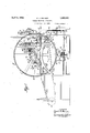
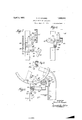
- FIG. 1 is a side elevation of an apparatus constructed in accordance with my invention, with certain parts which appear fully in other views either omitted or shown diagrammatically.
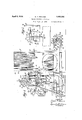
- Fig. 2 is a front elevation of the apparatus.
- Fig. 3 is an enlarged fragmentary elevational view of a printing device which I employ.
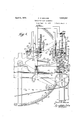
- Fig. 4 is an enlarged fragmentary view of a portion of the apparatus showing clearly certain parts which have been omitted in Fig. 1.
- Fig. 5 is a view drawn on the same scale as Fig. 4 and looking toward the left.
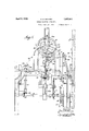
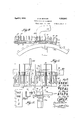
- Figs. 6,7, 8 and 9 are enlarged fragmentary views of clutch mechanism which I employ.
- Figs. 10, 11 and 12 are enlarged fragmentary views of certain parts of a selector device employed in the apparatus.-
- Figs. 13 to 16 are diagrammatic views illustrating the position of the selector members of the selector device for printing the thread in accordance with a simple example given hereinafter, and
- Fig. 17 is an enlarged view of a portion of a ratchet ring which is secured to the thread carrying drum.
- My improved thread printing apparatus comprises in general a drum A on which the thread is wound in a single layer, for example, a layer composed of say fifty threads in width; a printing carriage B adapted to travel back and forth in the axial direction of the drum and having a printing roll 20 contacting with the layer of thread on the drum to print transverse stripes of color thereon; driving mechanism 0 for rotating the drum to wind the thread thereon; driving mechanism D for operating the carriage in its back and forth travel; driving mechanism E for rotating the drum when the printing mechanism is outof operation; and
- the driving mechanism F for rotating the drum in steps when printing is being effected.
- the driving mechanism E may be referred to as a skipping mechanism or a mechanism for imparting rotative movement to the drum of greater amplitude than the step movement imparted to the drum by the driving mechanism F.
- the driving mechanism C comprises a drive shaft 21 controlled by any suitable means, such, for example, as the well known belt driven tight and loose pulley device indicated at 22, bevel gearing 23 for transmitting drive from the drive shaft 21 to the pinion shaft 24 carrying the pinion :25, and a gear 26 on the drum shaft 27 meshing with the pinion 25.
- any suitable means such as the well known belt driven tight and loose pulley device indicated at 22, bevel gearing 23 for transmitting drive from the drive shaft 21 to the pinion shaft 24 carrying the pinion :25, and a gear 26 on the drum shaft 27 meshing with the pinion 25.
- a ratchet ring is provided adjacent the periphery of the drum and at an edge thereof, which ratchet ring has a multiplicity of evenly spaced ratchet teeth 33, say, for example, six hundred and forty-eight.
- a ratchet pawl 34 is adapted to engage the teeth of the ratchet ring. The pawl 34: is operated to engage a tooth of the ring, rotate it with the drum a distance equal to the spacing of the teeth, then ratchet back to engage the next tooth, then advance the drum another notch and so on.
- the pawl is operated from a cam .35 which operates the pawl through suitable lover mechanism, in this instance comprising a lever 36 pivoted at 37 and having a cam roller 38 at one end contacting with the cam face and connected at its other end to an arm ill by means of link 40.
- the arm 89 is pivoted at 41 and has connected thereto a second arm 42 on which the pawl 34 is pivoted as indicated at 43.
- the link connection may be adjusted in the slots in the lever 36 and arm 39.
- the cam lever is maintained in engagement with the cam by means of a spring secured at one end to the lever and at the other end to the frame of the machine. Two oppositely disposed depressions are provided in the cam surface so that the pawl is operated twice for each revolution of the cam.
- the cam 35 is driven from a drive shaft 45 having a pinion 46 secured thereon meshing with a gear 47 secured on the cam shaft 35c.
- a clutch controls the pinion 46 for a purpose hereinafter appearing.
- the drive shaft 45 may be driven in any suitable manner as by means of a belt and pulley such as indicated at 48.
- the driving mechanism D for operating the printing carriage B and the structure of the carriage and its supports are as follows: A pair of rails 49 are supported from the frame of the machine below the drum and extend in the axial direction of the drum and the wheeled printing carriage E runs on the track thus provided.
- the carriage comprises a frame structure 50 adapted to support a well 51 for the coloring liquid, the well resting on a pair of supports 52 on the carriage frame.
- the printing roll 20 is supported in open top bearings 53 provided on the pivoted yoke-like member 54, which member is pivoted at 55 and spring pressed in an upward direction by means of springs 56.
- the member 54 is so located that the roll 20 dips into the liquid in the well 51.
- Back and forth movement of the carriage B is effected by means of an oscillating gear sector 57 engaging with a pinion 58 secured on a shaft 59.
- the shaft 59 carries a drum 60 around which a rope or cable 61 is wound for several. turns, the cable being secured at its end 62 to one end of the carriage frame and at its other end 63 to the other end of the carriage frame, the cable, however, first passing over a pulley 64 mounted in a fixed support, such as a bracket 65 secured to the rails.
- the gear sector 5'? is oscillated by means of a cranlr 57a and connecting rod 575, the crank in this instance being carried by the cam shaft 35a.
- the printing roll 20 is positively rotated as by means of a cable 66 passing around a pulley 67 having driving connection with the roll.
- the cable 66 is fastened both ends to a fixed part of the machine. pointed out that the cam 35, the crank 57a, and the length of travel. of the carriage relativ to'the width of the drum A are so callt is culated that the rotation of the drum by the mechanism F does not start until the roll 20 is out of contact with the thread and is completed before the roll again contacts with the thread.
- the apparatus as thus far described would only take care of printing a multiplicity of transverse stripes of the same color across the layer of threads, the spacing of which would correspond to the spacing of the teeth of the ratchet ring 32 and wits close spacing of the teeth would result in substantially solid coloring of the layer of thread.
- the layer of thread may be printed with a stripe of red followed by three stripes of I green, two stripes of black, three stripes of blue and so on.
- the selector mechanism just above referred to may comprise an endless chain G passing over end sprocket wheels 68 and 68a and over and intermediate driving sprocket wheel 68b. Suitable guides 69. 69a and 696 are provided for the chains.
- the sprocket wheel 68?) is driven from the shaft 30 through the medium of sprockets 71 and 72 over which a chain 73 passes.
- the chain G is only driven when the shaft 30 is rotating, and as the shaft 30 carries the pinion 28 which meshes with. the internal teeth 29 of the drum, it is apparent that the chain moves whenever the drum rotates, except, of course, when thread is being wound on the drum in which case the pinion 28 is out of mesh with the internal gear Referring now more particularly to Fi s.
- the endless chain J. is provided with a multiplicity of movable sel ctor plates 74, one for each tooth. 33 of the ratchet ring 32.
- the selector plates are numbered as indicated in 12 to correspond to the numbering on the ratchet ring ⁇ see Fig. 17), and they are mounted in slotted blocks 7 carried by the link plates 76 of the chain G.
- the se lector plates are movable in the blocks 75 from a position in which they do not project from the blocks to a position s iown at 7 5a in Figs. 11 and 12 in which they project from the blocks, the amount of the projection being determined by the stop shoulders 77 adapted to engage the blocks.
- Springs 78 may be employed to resiliently hold the selector plates in their selected positions.
- the lever 89 is pivoted at 91 on a plate 92 which is secured to a lever 93, as by means of a bolt 94.
- a rod 95 carrying a block 96 is connected to the lever 89 at 97 for operation thereby.
- a member 98 carried by the lever 93 is provided to guide the block 96 and rod 95 in their up and down movement.
- the lever 93 is secured at 99 to the rock shaft 100 of the clutch operating yoke 101, the rock shaft having its bearing in a bracket 102 secured to the main frame of the machine.
- the yoke 101 is provided with pins 103 operating in an annular groove 104 in the movable toothed clutch member 105. 7
- the clutch device just referred to is adapted to be thrown out, when the clutch device 105 and 106 of the mechanism F is thrown in, through means of a leverage system including a rock lever 112 having its lower end connected to the lever 93 by a link 113 and its upper end to a lever 114 by a link 115.
- the lever 114 is secured at 116 to the rock shaft 117 of the clutch operating yoke 118 having pins operating in a groove in the movable clutch member 108.
- the rock shaft 117 has its bearing in a bracket 119 which is secured to the frame of the machine.
- the printing device B With the clutch of the device E disengaged and the clutch of the device F engaged, the printing device B is operated to travel back and forth and the large thread carrying drum A is rotatedin a step by step movement, all as above fully described, it being noted that the drive shaft of the source of power is common to devices B and F.
- the skipping mechanism E which quickly rotates or advances the drum through the space or spaces where no print of the color being run is to occur, comprises the pinion 28 which meshes with the internal gear 29 of the drum, a bevel gear 120 on the pinion shaft 30, a vertically extending shaft 121 carrying a bevel gear 122 meshing with the bevel gear 120, a second bevel gear 123 on the shaft 121, a horizontally disposed shaft 124 carrying a bevel gear 125 meshing with the bevel gear 123 and also carrying a sprocket wheel 126, a sprocket wheel 127 secured on the shaft of gear 111 and a chain 129 passing over the sprocket wheels 126 and 127.
- the drive shaft 107 above referred to is driven by means of a belt driven pulley 133 having clutch connection with the shaft.
- the clutch connection comprises a movable clutch member 134 splined on the drive shaft 107 and a clutch member 135 carried by the pulley.
- a clutch yoke 136 and operating bar 137 are provided for operating the movable member 134.
- the clutch device 134 and 135 may be automatically thrown out when all prints for one revolution of the drum have been completed, as by means of a pin 138 carried by the gear 26 adapted to engage a lug 139 on the flexible arm 140 connected to the clutch operating yoke 136.
- a hand operated ratchet Wheel 141 may be provided on the pinion shaft 30 for the pur pose of rotating the drum by hand as this may be desirable when setting the machine up for operation.
- the operator is enabled to make his selections on the selector device well ahead of the time that the selected members actually perform their workwhich affords him opportunity to check the selections and thus avoid misprints.
- the apparatus is automat-ic in its operation, one operator may take care of a number of machines.
- Thread printing apparatus including a thread carrying drum, means for imparting uniform step by step rotative movement to the drum, means for imparting rotative movement to the drum of greater amplitude than step movement, selective means for determining which movement is to be imparted to the drum, means actuated by said selective means to etlect the selected drive, and a device for printing transverse stripes of color on the thread carried by the drum.
- Thread printing apparatus including a thread carrying drum, means for imparting uniform step by step rotative movement to the drum, means for imparting rotative movement to the drum of greater amplitude than step movement, a clutch device controlling said first mentioned means, a clutch device controlling said second mentioned means, a selector device for determining which movement is to be imparted to the drum, means for engaging and disengaging said clutches, means actuated by the selector device to engage one of the clutch devices and disengage the other in accordance with the selection made, and a device for printing transverse stripes of color on the thread carried by the drum.
- Thread printing apparatus including a thread carrying drum, means for rotating the drum in steps, means for rotating the drum in continuous movement of greater amplitude than step movement, selective means for determining which movement is to be imparted to the drum, means actuated by the selective means for controlling the two first mentioned means, and a device for printing transverse stripes of color on the thread carried by the drum.
- Thread printing apparatus including a thread carrying drum, pawl and ratchet means for rotating the drum in steps, gear means for rotating the drum in continuous movement of greater amplitude than step movement, selective means for determining which movement is to be imparted to the drum, means actuated by the selective means to effect drive to the drum through either the pawl and ratchet means or the gear means in accordance with the selection made, and a device for printing transverse stripes of color on the thread carried by the drum.
- thread printing apparatus including a drum carrying a layer of thread to be printed, a printing device for printing transverse stripes of color on said layer and means for rotating the drum in steps correspond ing in number to the number of stripes to be printed, the combination of power means for rotating the drum in continuous movement of greater amplitude than step movement, and means for efiecting either step by step or continuous movement of the drum.
- thread printing apparatus including a drum carrying a layer of thread to be printed, a printing device for printing transverse stripes of color on said layer and means for rotating the drum in steps corresponding in number to the number of stripes to be printed, the combination of power means for rotating the drum in continuous movement of greater amplitude than step movement, and selective means operating to select either step by step or continuous movement for the drum.
- Thread printing apparatus comprising in combination, a drum on which the thread to be printed is wound in a single layer, a printing device movable axially of the drum and having a printing roll adapted to contact with the thread on the drum, power means for rotating the drum in steps, power means for rotating the drum in continuous movement greater than step movement, a driving member for the first power means, a driving member for the second power means, and means for connecting and disconnecting said driving members to their respective power means, said connecting and disconnecting means being interconnected so that only one of the power means receives drive at a time.
- Thread printing apparatus comprising in combination, a drum on which the thread to be printed is wound in a single layer, a
- Thread printing apparatus including a thread carrying drum; power means for imparting uniform step by step rotative movement to the drum; power means for imparting rotative movement to the drum of greater amplitude than step movement; a clutch device controlling the first mentioned power means; a clutch device controlling the second mentioned power means; means connecting said clutch devices for operation in unison so that one clutch is engaged when the other is disengaged; actuating means for said interconnected clutch devices; a selector device operatively associated with said actuating means for governing the actuation of the clutches including an endless chain, means for driving the chain, and selector members movably mounted on the chain, said members being movable to positions in which they operate on said actuating means to cause engagement or" one clutch and disengagentient of the other and to positions in which they permit said actuating means to cause disengagement of the first mentioned clutch and engagement of the second mentioned clutch; and'a device for printing transverse stripes of color on the thread carried by the drum.
- Thread printing apparatus including a thread carrying drum; power means for imparting uniform step by step rotative movement to the drum; power means for imparting rotative movem nt to the drum of greater amplitude than step movement; a clutch device controlling the first mentioned pow means; a clutch device controlling the secomentioned power means; means connecti g said clutch devices for operation in unison so that one clutch is engaged when the other is disengaged; actuating means for said interconnected clutch devices; a selector device operatively associated with said actuating means for governing the actuation oi the clutches including an endless chain, means driven from the rotatable drum for driving the chain, and selector members movably mounted on the chain, said members being movable to positions in which they operate on said actuating means to cause engagement of one clutch and disengagement of the other and to positions in which they permit said actuating means to cause disengagement of the first mentioned clutch and engagement of the second mentioned clutch; and a device for printing transverse stripes of color on the thread carried by the
- Thread printing apparatus including a drum on which a layer of thread to be printed is wound, a printing device adapted to travel back and forth axially of the drum to print transverse stripes 01"" color on the layer of thread, drive means for said printing device, drive means for ir a iiig uni form step by step rotative movement to th/ drum, a common source of power for both of said drive means, drive means for imparting rotative movement to the drum of greater amplitude than step movement, a source of power for the last mentioned drive means.
- clutch means controlling th first source of power, clutch means contro the second source of power, a selector device operativelv associated with said clutch means having a plurality of selector members and means operated thereby for actuating the clutches,
- selector members being adapted to be placed in positions whereby the clutches will be actuated to effect uniform step by step rotation of the drum at times and rotative movement of greater amplitude than step movement at other times.
- lhread printing apparatus including a drum on which a layer of thread to be printed is wound, drive means for rotating the drum to wind the thread thereon, a source of power for said drive means, a printing device adapted to travel back and forth are ially oi the drum to print transverse stripes of color on the layer of thread, drive means for said printing device, drive means for imparting uniform step by step rotative movement to the drum, a common source of power for both oi saic drive means, drive means for imparting rotative movement to the drum or greater amplitude than step movement, source of power for the last mentioned drive means, means controlling each of said three sources of power whereby two may be rendered idle and the other active and selector means including selector plates operatively associated with the control means of the second and third mentioned sources of power, said plates being adapted to be set in positions to operate the control means to effect rotation of the drum in successive steps certain of which are of greater amplitude than others.
- Thread printing apparatus including a drum on which a layer of thread to be printed is wound, said dr m1 having a ratchet ring, a pawl device engaging the teeth of said ring to impart rotative step by step movement to the drum, cam and lever mechanism for actuating the pawl device, drive means for said cam, a printing device adapted to travel back and forth axially of the drum to print transverse stripes of color on the layer of thread, means driven from the cam drive means for imparting such movement to the printing device, a clutch for throwing said drive means into and out of driving engagement, shift means for the clutch, cam means for actuating said shift means, said cam means being rotatable with the mentioned earn, a stop member fixedly associated with said cam means, a movable stop member carried by the clutch shift means, a selector device for moving said movable member into a position in which it is engaged by said cam means to disengage the clutch and in which is engaged by the tired stop member to stop said pawl and printing devices, and into a
- Thread printing apparatus including a thread carrying drum, means for imparting uniform step by step rotative movement to the drum, means for imparting rotative movement to the drum of greater amplitude than step mo 'ement, selective means for determining which movement is to be imparted to the drum, means actuated by said selective means to effect the selected drive, a device for printing transverse stripes of color on the thread carriet, by the drum, and means for automatically stopping the drum when the drum has made a complete revolution.
- Thread printing apparatus including a thread carrying drum, a printing device for printing transverse stripes of color on the thread carried by the d um, power means for driving the drum in uniform step by step rotative movement, power means for driving said printing device, power means for driving the drum in rotative movement of greater amplitude than step movement, a drive shaft common to the first two power means, a clutch for establishing and discstablishing driving connection between said shaft and said power means, a drive shaft for the last mentioned power means, a clutch for establishing and disestablishing driving connection between said last mentioned shaft and power means, means interconnecting said clutches so that one is in when the other is out, means for driving the first shaft, means driving said second shaft, actuating means for said clutches, a selector device governing the actuation of the clutches, and means for establishing and disestablishing driving connection between said last mentioned driving means and said second shaft.
- Thread printing apparatus including a thread carrying drum, a printing device for printing transverse stripes of color on the thread carried by the drum, power means for driving the drum in uniform step by step rotative movement, power means for driving said printing device, power means for driving the drum in rotative movement of greater amplitude than step movement, a drive shaft common to the first two power means, a clutch for establishing and disestablishing driving connection between said last mentioned shaft and power means, means interconnecting said clutches so that one is in when the other is out, means for driving the first shaft, means driving said second shaft, actuating means for said clutches, a selector device governing the actuation of the clutches, and means for establishing and disestablishing driving connection between said last mentioned driving means and said second shaft, together with means automatically disestablishing said last mentioned driving connection when said drum has made a complete revolution.
- Thread printing apparatus comprising a drum carrying a layer of thread to be printed, means for rotating said drum, movable means provided with spaced controlling devices, means for imparting movement to said movable means from the drum, means operated by said devices for intermittently turning said drum to prescribed different printing positions, and a device for printing transverse stripes of color on the layer of thread carried by the drum.
- Thread printing apparatus comprising a drum carrying a layer of thread to be printed, means for rotating said drum, an endless chain provided with spaced controlling devices, means for driving said chain from the drum, means operated by said devices for intermittently turning said drum to prescribe different printing positions, and a device for printing transverse stripes of color on the layer of thread carried by the drum.
- Thread printing apparatus comprising a drum carrying a layer of thread to be printed, means for rotating said drum, movable means provided with spaced selective controlling devices, means for imparting movement to said movable means from the drum, means operated by said devices for intermittently turning said drum to prescribed different printing positions, and a device for printing transverse stripes of color on the layer of thread carried by the drum.
- Thread printing apparatus comprising a thread carrying drum, means for selectively imparting rotative movement to the drum in steps of predetermined amplitude including a chain connected to said drum to be rotated thereby, selector means carried by said chain, and means operated by the selector means to rotate the drum in steps, the amplitudes of which are determined by the setting of the selector means.
Landscapes
- Engineering & Computer Science (AREA)
- Textile Engineering (AREA)
- Inking, Control Or Cleaning Of Printing Machines (AREA)
Description
April 5, 1932. B BONNER 7 1,852,641
THREAD PRINTING APPARATUS {filed Sept. 18, 1929 e Sheets-Sheet 1 INVENTOR 00M 61M BY WYMW ATTORNEYS April 1932'- D. B. BONNER 1,852,641
THREAD PRINTING APPARATUS Filed Sept. 18, 1929 6 Sheets-Sheet 2 INVENTOR 10M [1.
W MM
ORNEYS April 5, 1932. D. B. BONNER 1,852,641
THREAD PRINTING APPARATUS Filed Sept. 18. 1929 a Sheets-Shegt s llil IIIIIIHIIHIII llllll E;
.III I IIIIIIIIHIIIIIIHIIII INVENTOR ATTORNEYS April 1932- V D. B. BONN ERV 1,852,641
THREAD PRINTING APPARATUS Filed Sept. l8, 1929 6 Sheets-Sheet 4 INVENTOR April 5, 1932.
THREAD PRINTING APPARATUS Filed Sept. 18, 1929 6 Sheets-Sheet 5 Jaw "HIWIWIHIIHHII' INVENTOR fim-Jflmw vPMa I ATTORNEYS April 1932- D. BONNER 1,852,641
THREAD PRINTING APPARATUS Filed Sept. 18, 1929 6 Sheets-Sheet 6 74 79 A r J .L L k LI 1 a0 lbENT OR ATTORNEY5 Patented Apr. 5, 1932 DANIEL BUTLER BONNER, OF PHILADELPHIA, PENNSYLVANIA THREAD EPBINTING APPARATUS Application filed September 18, 1929. Serial No. 393,544.
This invention relates to thread printing apparatus and is particularly useful for printing colors on yarn which is ultimately to be made into carpets.
The apparatus is of a type in which the thread or yarn to be printed is wound on a large drum in a single layer and in which transverse stripes of different colors are printed on the layer of thread. The number m of different colors to be employed and the order in which the color stripes are to be printed on the layer of thread depends on the particular design to be produced in the finished carpet. The usual practice is for a de- 1 signer to provide a chart for the operation of the apparatus, giving the number of stripes desired of each color and the order in which it is desired to have them printed on the thread.
After printing is completed the layer of thread is removed from the drum, treated to make the colors fast, and finally each thread comprising the layer is wound on a spool. Thespools of printed thread are then employed in a carpet making machine in which the thread is withdrawn from the spoolsin a manner to produce the desired design.
I am aware that apparatus of the type above mentioned has heretofore been employed, but has not been altogether satisfactory, with the result that the demand for such apparatus has almost entirely dropped off.
in the known apparatus referred to, the thread was wound onto a drum having ratch et mechanism associated therewith for rotating the drum in a multiplicity of uniform steps. A printing device for printing transverse stripes of color on the thread was employed, which device cooperated with the ratchet mechanism so that a stripe of color was printed with each step movement of the drum. However, since stripes of difi'erent colors were to be printed on the thread and since the apparatus only tool: care of printing stripes of one color at a time for the entire circumference of the drum, it was necessary when printing one color to skip certain spaces to leave room for the other colors, and, therefore, the printing device had to be idle during movement of the drum through the spaces. This was accomplished by disengaging the drive for the ratchet mechanism and printing device and by ratcheting the drum along by hand through the steps representing the spaces.
The above operation was not only veryti-me consuming because of the slow step by step movement, but also was uncertain for the reason that the provision of the proper number of skips between prints depended entirel on the watchfulness of the opera-tor, and is was not uncommon for an operator to lose count and thereby skip the wrong number of spaces, thus causing the print to occur at the wrong place on the thread.
One of the primary objects of my invention is the provision of apparatus of the character described in which serious drawbacks, such as pointed out above, are overcome. i w
A further object of'my invention is the provision of power mechanism for quickly ro tating the drum of the apparatus when skipping over a plurality of steps.
Another object of my invention is the pro- T..- vision of apparatus of the character .described in which change from uniform step by step movement of the drum to rotative movement of greater amplitude than step movement is automatically brought about.
Still another object resides in providing selector mechanism for determining the kind of rotative movement to beimparted ;to the drum.
Another object resides in the provision of apparatus of the character described in which printing operations are automatically stopped during skipping rotative movement of the drum.
A more specific object resides in the provision of power means for driving the drum in uniform step by step movement, power means for driving the .drum in rotative movement of greater amplitude than step 9 movement, power means for driving a printing device and associated means for selectively controlling said drives to effect printing during step by step movementuand rendering the printing device idle during rotative movement of greater amplitude than step movement.
A further object resides in the provision of apparatus of the character described having selective means adapted to be set to cause rotation of the drum in steps of varying amplitude.
A still further object is the provision of means for automatically stopping the drum rotating devices when the drum has made a complete revolution.
Other objects relate to certain details of construction which will appear fully hereinafter.
How the foregoing, together with such other objects and advantages as may hereinafter appear, or are incident to the invention, are realized is illustrated in preferred form in the accompanying drawings, in which Fig. 1 is a side elevation of an apparatus constructed in accordance with my invention, with certain parts which appear fully in other views either omitted or shown diagrammatically.
Fig. 2 is a front elevation of the apparatus.
Fig. 3 is an enlarged fragmentary elevational view of a printing device which I employ.
Fig. 4 is an enlarged fragmentary view of a portion of the apparatus showing clearly certain parts which have been omitted in Fig. 1.
Fig. 5 is a view drawn on the same scale as Fig. 4 and looking toward the left.
Figs. 6,7, 8 and 9 are enlarged fragmentary views of clutch mechanism which I employ.
Figs. 10, 11 and 12 are enlarged fragmentary views of certain parts of a selector device employed in the apparatus.-
Figs. 13 to 16 are diagrammatic views illustrating the position of the selector members of the selector device for printing the thread in accordance with a simple example given hereinafter, and
Fig. 17 is an enlarged view of a portion of a ratchet ring which is secured to the thread carrying drum.
My improved thread printing apparatus comprises in general a drum A on which the thread is wound in a single layer, for example, a layer composed of say fifty threads in width; a printing carriage B adapted to travel back and forth in the axial direction of the drum and having a printing roll 20 contacting with the layer of thread on the drum to print transverse stripes of color thereon; driving mechanism 0 for rotating the drum to wind the thread thereon; driving mechanism D for operating the carriage in its back and forth travel; driving mechanism E for rotating the drum when the printing mechanism is outof operation; and
driving mechanism F for rotating the drum in steps when printing is being effected. The driving mechanism E may be referred to as a skipping mechanism or a mechanism for imparting rotative movement to the drum of greater amplitude than the step movement imparted to the drum by the driving mechanism F.
The driving mechanism C comprises a drive shaft 21 controlled by any suitable means, such, for example, as the well known belt driven tight and loose pulley device indicated at 22, bevel gearing 23 for transmitting drive from the drive shaft 21 to the pinion shaft 24 carrying the pinion :25, and a gear 26 on the drum shaft 27 meshing with the pinion 25. Thus it will be seen that when the belt is shifted to the tight pulley, drive is transmitted from the drive shaft 21 to the drum through the gearing just described. As soon as a layer of thread is wound across the face of the drum the driving mechanism C is thrown out of operation by shifting the belt to the loose pulley. It is pointed out that when thread is being wound onto the drum the other mechanisms of the apparatus above referred to are put into their neutral positions through the medium of suitable clutch arrangements to be fully described hereinafter. In particular reference to the pinion 28 shown in Figures 1, 2, i and 5, this pinion is shifted out of mesh with the internal gear 29 of the drum when the thread winding operation is taking place by moving it with its shaft 30 to the left as viewed in Figures 2 and 5. A handle 31 is provided for this purpose, which handle may be detachably secured to the frame of the machine when the pinion is in meshed position.
The various mechanisms for accomplishing the printing of transverse stripes of various colors in proper order across the layer of thread on the drum will now be described.
Referring first to the driving mechanism F for rotating the drum in uniform steps, i. e., in a plurality of intermittent rotative movements, it will be seen that a ratchet ring is provided adjacent the periphery of the drum and at an edge thereof, which ratchet ring has a multiplicity of evenly spaced ratchet teeth 33, say, for example, six hundred and forty-eight. A ratchet pawl 34 is adapted to engage the teeth of the ratchet ring. The pawl 34: is operated to engage a tooth of the ring, rotate it with the drum a distance equal to the spacing of the teeth, then ratchet back to engage the next tooth, then advance the drum another notch and so on.
The pawl is operated from a cam .35 which operates the pawl through suitable lover mechanism, in this instance comprising a lever 36 pivoted at 37 and having a cam roller 38 at one end contacting with the cam face and connected at its other end to an arm ill by means of link 40. The arm 89 is pivoted at 41 and has connected thereto a second arm 42 on which the pawl 34 is pivoted as indicated at 43. The link connection may be adjusted in the slots in the lever 36 and arm 39. The cam lever is maintained in engagement with the cam by means of a spring secured at one end to the lever and at the other end to the frame of the machine. Two oppositely disposed depressions are provided in the cam surface so that the pawl is operated twice for each revolution of the cam.
The cam 35 is driven from a drive shaft 45 having a pinion 46 secured thereon meshing with a gear 47 secured on the cam shaft 35c. A clutch controls the pinion 46 for a purpose hereinafter appearing. The drive shaft 45 may be driven in any suitable manner as by means of a belt and pulley such as indicated at 48.
The driving mechanism D for operating the printing carriage B and the structure of the carriage and its supports are as follows: A pair of rails 49 are supported from the frame of the machine below the drum and extend in the axial direction of the drum and the wheeled printing carriage E runs on the track thus provided. The carriage comprises a frame structure 50 adapted to support a well 51 for the coloring liquid, the well resting on a pair of supports 52 on the carriage frame.
The printing roll 20 is supported in open top bearings 53 provided on the pivoted yoke-like member 54, which member is pivoted at 55 and spring pressed in an upward direction by means of springs 56. The member 54 is so located that the roll 20 dips into the liquid in the well 51.
Back and forth movement of the carriage B is effected by means of an oscillating gear sector 57 engaging with a pinion 58 secured on a shaft 59. The shaft 59 carries a drum 60 around which a rope or cable 61 is wound for several. turns, the cable being secured at its end 62 to one end of the carriage frame and at its other end 63 to the other end of the carriage frame, the cable, however, first passing over a pulley 64 mounted in a fixed support, such as a bracket 65 secured to the rails.
The gear sector 5'? is oscillated by means of a cranlr 57a and connecting rod 575, the crank in this instance being carried by the cam shaft 35a. Thus it will be seen that when the cam shaft rotates, the printing carriage with its printing roll traverses the face of the large drum A so that stripes of color are deposited on the thread by the printing roll which is in spring pressed contact with the thread. The printing roll 20 is positively rotated as by means of a cable 66 passing around a pulley 67 having driving connection with the roll. The cable 66 is fastened both ends to a fixed part of the machine. pointed out that the cam 35, the crank 57a, and the length of travel. of the carriage relativ to'the width of the drum A are so callt is culated that the rotation of the drum by the mechanism F does not start until the roll 20 is out of contact with the thread and is completed before the roll again contacts with the thread.
The apparatus as thus far described would only take care of printing a multiplicity of transverse stripes of the same color across the layer of threads, the spacing of which would correspond to the spacing of the teeth of the ratchet ring 32 and wits close spacing of the teeth would result in substantially solid coloring of the layer of thread. However, since propose to print stripes of different colors on the layer of thread in various arrangements according to the requirements for producing a desired design in the material into which the thread is ultimately to be fabricated, I have provided mechanisms cooperating with the above to make this possible. For example, it may be desired to employ four different colorsred, green, black, and blue' -and the ultimate design to he produced may require that the layer of thread be printed with a stripe of red followed by three stripes of I green, two stripes of black, three stripes of blue and so on.
In order to accomplish this I print all of the stripes of one color in their proper spacing for the entire circumference of the drum. This, of course, means that spaces must be left between the stripes to accommodate the remaining colors. The means for selecting the points where stripes are to be printed and for causing skipping where spaces are to be left will be described presently. After having printed one color I lift out the removable well 51 and its printing roll and insert a well and roll containing coloring liquid of the next color and then resume printing stripes of this color in proper spacing re -tive to the first stripes, and so on until all of the colors have been printed.
The selector mechanism just above referred to may comprise an endless chain G passing over end sprocket wheels 68 and 68a and over and intermediate driving sprocket wheel 68b. Suitable guides 69. 69a and 696 are provided for the chains. The sprocket wheel 68?) is driven from the shaft 30 through the medium of sprockets 71 and 72 over which a chain 73 passes. Thus the chain G is only driven when the shaft 30 is rotating, and as the shaft 30 carries the pinion 28 which meshes with. the internal teeth 29 of the drum, it is apparent that the chain moves whenever the drum rotates, except, of course, when thread is being wound on the drum in which case the pinion 28 is out of mesh with the internal gear Referring now more particularly to Fi s. 10, 11 and 12, the endless chain J. is provided with a multiplicity of movable sel ctor plates 74, one for each tooth. 33 of the ratchet ring 32. The selector plates are numbered as indicated in 12 to correspond to the numbering on the ratchet ring {see Fig. 17), and they are mounted in slotted blocks 7 carried by the link plates 76 of the chain G. The se lector plates are movable in the blocks 75 from a position in which they do not project from the blocks to a position s iown at 7 5a in Figs. 11 and 12 in which they project from the blocks, the amount of the projection being determined by the stop shoulders 77 adapted to engage the blocks. Springs 78 (see Fig. 11) may be employed to resiliently hold the selector plates in their selected positions.
Assuming now that it is desired to print the thread in four colors in accordance with the example given above, then the operator, starting with selector plate marked #1, will push this plate out so that it projects from the block, he will then push out plate marked #10, then #19, and so on until plate # 1 again comes around which completes the operation for the first color. In Figures 10, 11 and 12 T have shown plate marked #1 pushed out, and in Figures 13 to 16 inclusive 1 have diagrammatically illustrated the position of the plates for printing the red, green, black and blue colors respectively. ihe operator may be provded with a chart for convenience in selecting the plates to be moved and he may push the plates out as the plates come over the front sprocket wheel 68a;
Referring now more particularly to Figures 4 to 12 inclusive, it will be seen that as the chain revolves the projecting portion of plate marked #1 engages the free or hooked end 79 of the lever 80, causing it to rock on its pivot 81 so that a downward pull is given to the link 82. The link 82 is connected to a lever 83 pivoted at 84 and having an arcuate rack 85 at its free end, the are of the rack being struck from the center of pivot of the lever. The rack 85 meshes with teeth 86 on a lever 87 which is pivoted at 88 and from the center of which pivot the teeth 86 are located. The toothed lever 87 is connected with another lever 89 by means of a link 90. The lever 89 is pivoted at 91 on a plate 92 which is secured to a lever 93, as by means of a bolt 94. A rod 95 carrying a block 96 is connected to the lever 89 at 97 for operation thereby. A member 98 carried by the lever 93 is provided to guide the block 96 and rod 95 in their up and down movement.
The lever 93 is secured at 99 to the rock shaft 100 of the clutch operating yoke 101, the rock shaft having its bearing in a bracket 102 secured to the main frame of the machine. The yoke 101 is provided with pins 103 operating in an annular groove 104 in the movable toothed clutch member 105. 7
Following through the lever system just described, it will be see that when a projecting selector plate engages the hooked end O 79 of the lever 80, the link 82 is pulled downwardly to operate the toothed portions of the levers 83 and, 87 in a manner to move the lever 87 downwardly. This causes a downward pull on link 90 and consequently the lever 89 is caused to rock downwardly, pulling the block 96 downwardly in its guide.
.Vith the block 96 in its down position a pair of cams 106a carried by the cam shaft gear 47 and positioned 180 apart will clear the block as the gear rotates and this permits the lever 93 to assume a position in which the teeth of the movable clutch member 105 are engaged with the teeth of a clutch member 106 formed as part of the pinion 46, and since the movable clutch member 105 is splined to the shaft 45, drive will be effected to the gear 47. The lever is kept in this position as long as projecting selector plates engage the lever 80.
It is pointed out that when the cam shaft 35 is being rotated from the shaft 45, it is important that the drive shaft 107 of the mechanism E is running idle, and to accomplish this I provide a movable toothed clutch member 108 splined on the shaft 107 and adapted to be moved into and out of engagement with a clutch member .109 carried by a pinion 110 meshing with a gear 111. The operation of the skipping mechanism will be described hereinafter.
The clutch device just referred to is adapted to be thrown out, when the clutch device 105 and 106 of the mechanism F is thrown in, through means of a leverage system including a rock lever 112 having its lower end connected to the lever 93 by a link 113 and its upper end to a lever 114 by a link 115. The lever 114 is secured at 116 to the rock shaft 117 of the clutch operating yoke 118 having pins operating in a groove in the movable clutch member 108. The rock shaft 117 has its bearing in a bracket 119 which is secured to the frame of the machine.
From the foraging it will be seen that any movement transmitted to the lever 93 will be transmitted to the lever 114 to move said lever in the opposite direction, and consequently when the lever 93 moves in a direction to engage the clutch 105, 106, the lever 118 is moved in the opposite direction to disengage the clutch 108.
With the clutch of the device E disengaged and the clutch of the device F engaged, the printing device B is operated to travel back and forth and the large thread carrying drum A is rotatedin a step by step movement, all as above fully described, it being noted that the drive shaft of the source of power is common to devices B and F.
The skipping mechanism E, which quickly rotates or advances the drum through the space or spaces where no print of the color being run is to occur, comprises the pinion 28 which meshes with the internal gear 29 of the drum, a bevel gear 120 on the pinion shaft 30, a vertically extending shaft 121 carrying a bevel gear 122 meshing with the bevel gear 120, a second bevel gear 123 on the shaft 121, a horizontally disposed shaft 124 carrying a bevel gear 125 meshing with the bevel gear 123 and also carrying a sprocket wheel 126, a sprocket wheel 127 secured on the shaft of gear 111 and a chain 129 passing over the sprocket wheels 126 and 127. 'While the above gearing is driven by the drum when step by step operation of the drum is taking place, it is to be observed that such drive is merely idle because the clutch device 108 and 109 is disengaged at that time.
Drive of the drum through means of the skipping mechanism occurs only when the clutch device 105 and 106 is disengaged and the clutch device 108 and 109 engaged and the manner in which such drive takes place is as follows:
Assuming now the selector chain G has moved so that the projecting plate marked #1 has passed the hooked lever 80, then the hooked end of the lever will drop, under in fluence of a spring 130 (see Fig. 4), causing the block 96 to be moved upwardly through the medium of leverage above fully described. With this hlock in its upper position it will lie in the path of the cams 106 and 106a and as soon as the cam surface 131 of the nearest cam comes around, it engages the projecting portion of the block and rocks the lever 93, rock shaft 100 and clutch yoke 101 in a direction to disengage the clutch member 105 from the member 106 and at the same time causes tie clutch member 108 to engage the clutch member 109 because of lever and linkage 112, 113, 114 and 115. The cams 106a are also provided with stop shoulders 132 adapted to be engaged by the block 96 to stop the wheel 47.
With the stopping of the wheel 47 the back and forth motion of the printing carriage is stopped as is also the intermittent or step by step movement of the drum A. The drum A, however, continues to rotate because of the engagement of the clutch device 108 and 109, the drive for the drum being from shaft 107 to pinion 28 and internal gear 29 through the chain and gear drive above fully described. Thus, it will be seen that a great saving in time is provided through means of the skipping mechanism which causes the drum to rotate relatively fast from one point of print to the next. In the particular printing example above given eight spaces are skipped between prints of red color, siX between prints of green, seven between prints of black and six between prints of blue. lVith sir: hundred and forty-eight total spaces it will be seen that considerable time would be consumed if step by step movement of the drum were employed throughout the operation.
From the foregoing it will be seen that whenever there is a projecting selector plate presented to the hooked lever 80 the block 96 is retracted, the clutch device'105 and 106 engaged and the clutch device 108 and 109 disengaged, thus causing printing to be effected, and then whenever retracted selector plates are presented to the lever 80, the block 96 is projected into the path of the cams 106a, causing the clutch device 105 and 106 to be disengaged and the clutch device 108 and 109 to be engaged, thus stopping the printing operation and step by step movement of the drum and causing the drum to rotate by pinion drive. In pinion drive the pawl 34 merely ratchets past the ratchet teeth 33.
The drive shaft 107 above referred to is driven by means of a belt driven pulley 133 having clutch connection with the shaft. The clutch connection comprises a movable clutch member 134 splined on the drive shaft 107 and a clutch member 135 carried by the pulley. A clutch yoke 136 and operating bar 137 are provided for operating the movable member 134. Thus, if it is desired to stop all operations for example, as would be the case at the end of all the prints, the operating'bar 137 is moved in a direction to disengage the clutch member 134 from the clutch member 135 which causes the pulley 133 to run idle. In starting up operations again the operating bar 137 is moved to cause engagement of this clutch device.
If desired the clutch device 134 and 135 may be automatically thrown out when all prints for one revolution of the drum have been completed, as by means of a pin 138 carried by the gear 26 adapted to engage a lug 139 on the flexible arm 140 connected to the clutch operating yoke 136.
A hand operated ratchet Wheel 141 may be provided on the pinion shaft 30 for the pur pose of rotating the drum by hand as this may be desirable when setting the machine up for operation. An operating handle 142 pivoted on the shaft 30 and carrying a pawl 143 engaging the ratchet Wheel is provided for effecting said hand operation.
Reverting now to the selector mechanism it Will be seen that as the chain G rotates the projecting selector plates may be returned to their retracted positions as by means of a spring pressed bar 144 located in their path and at a point beyond the hooked lever 80.
Through the practice of my invention the operator is enabled to make his selections on the selector device well ahead of the time that the selected members actually perform their workwhich affords him opportunity to check the selections and thus avoid misprints. By virtue of the fact that the apparatus is automat-ic in its operation, one operator may take care of a number of machines.
Although I have given. an example in which four colors are employed and in which the colors would be printed in a certain order, it is to be understood that a greater number of colors may be employed and printed in any order desired in accordance with the setting of the selector members of the selector device, for the device is capable of being set to impart steps of varying amplitude to the drum in any predetermined arrangement or successive order.
I claim 1. Thread printing apparatus including a thread carrying drum, means for imparting uniform step by step rotative movement to the drum, means for imparting rotative movement to the drum of greater amplitude than step movement, selective means for determining which movement is to be imparted to the drum, means actuated by said selective means to etlect the selected drive, and a device for printing transverse stripes of color on the thread carried by the drum.
2. Thread printing apparatus including a thread carrying drum, means for imparting uniform step by step rotative movement to the drum, means for imparting rotative movement to the drum of greater amplitude than step movement, a clutch device controlling said first mentioned means, a clutch device controlling said second mentioned means, a selector device for determining which movement is to be imparted to the drum, means for engaging and disengaging said clutches, means actuated by the selector device to engage one of the clutch devices and disengage the other in accordance with the selection made, and a device for printing transverse stripes of color on the thread carried by the drum.
3. Thread printing apparatus including a thread carrying drum, means for rotating the drum in steps, means for rotating the drum in continuous movement of greater amplitude than step movement, selective means for determining which movement is to be imparted to the drum, means actuated by the selective means for controlling the two first mentioned means, and a device for printing transverse stripes of color on the thread carried by the drum.
4. Thread printing apparatus including a thread carrying drum, pawl and ratchet means for rotating the drum in steps, gear means for rotating the drum in continuous movement of greater amplitude than step movement, selective means for determining which movement is to be imparted to the drum, means actuated by the selective means to effect drive to the drum through either the pawl and ratchet means or the gear means in accordance with the selection made, and a device for printing transverse stripes of color on the thread carried by the drum.
5. In thread printing apparatus including a drum carrying a layer of thread to be printed, a printing device for printing transverse stripes of color on said layer and means for rotating the drum in steps correspond ing in number to the number of stripes to be printed, the combination of power means for rotating the drum in continuous movement of greater amplitude than step movement, and means for efiecting either step by step or continuous movement of the drum.
6. In thread printing apparatus including a drum carrying a layer of thread to be printed, a printing device for printing transverse stripes of color on said layer and means for rotating the drum in steps corresponding in number to the number of stripes to be printed, the combination of power means for rotating the drum in continuous movement of greater amplitude than step movement, and selective means operating to select either step by step or continuous movement for the drum.
7. Thread printing apparatus comprising in combination, a drum on which the thread to be printed is wound in a single layer, a printing device movable axially of the drum and having a printing roll adapted to contact with the thread on the drum, power means for rotating the drum in steps, power means for rotating the drum in continuous movement greater than step movement, a driving member for the first power means, a driving member for the second power means, and means for connecting and disconnecting said driving members to their respective power means, said connecting and disconnecting means being interconnected so that only one of the power means receives drive at a time.
8. Thread printing apparatus comprising in combination, a drum on which the thread to be printed is wound in a single layer, a
printing device movable back and forth a:&-
ially of the drum and having a printing roll adapted to contact with the layer of thread on the drum to print transverse stripes of color thereon, means for rotating the drum in steps, means for imparting back and forth stroke to the printing device, drive means common to the two last mentioned means, drive means for rotating the drum in continuous movement greater than step movement, clutch means controlling said first mentioned drive means, clutch means controlling said second mentioned drive means, means interconnecting said clutch means to hold one clutch means out when the other is in, and means for operating said clutch means through the medium of the interconnecting means.
9. Thread printing apparatus including a thread carrying drum; power means for imparting uniform step by step rotative movement to the drum; power means for imparting rotative movement to the drum of greater amplitude than step movement; a clutch device controlling the first mentioned power means; a clutch device controlling the second mentioned power means; means connecting said clutch devices for operation in unison so that one clutch is engaged when the other is disengaged; actuating means for said interconnected clutch devices; a selector device operatively associated with said actuating means for governing the actuation of the clutches including an endless chain, means for driving the chain, and selector members movably mounted on the chain, said members being movable to positions in which they operate on said actuating means to cause engagement or" one clutch and disengagentient of the other and to positions in which they permit said actuating means to cause disengagement of the first mentioned clutch and engagement of the second mentioned clutch; and'a device for printing transverse stripes of color on the thread carried by the drum.
10. Thread printing apparatus including a thread carrying drum; power means for imparting uniform step by step rotative movement to the drum; power means for imparting rotative movem nt to the drum of greater amplitude than step movement; a clutch device controlling the first mentioned pow means; a clutch device controlling the secomentioned power means; means connecti g said clutch devices for operation in unison so that one clutch is engaged when the other is disengaged; actuating means for said interconnected clutch devices; a selector device operatively associated with said actuating means for governing the actuation oi the clutches including an endless chain, means driven from the rotatable drum for driving the chain, and selector members movably mounted on the chain, said members being movable to positions in which they operate on said actuating means to cause engagement of one clutch and disengagement of the other and to positions in which they permit said actuating means to cause disengagement of the first mentioned clutch and engagement of the second mentioned clutch; and a device for printing transverse stripes of color on the thread carried by the drum.
11. Thread printing apparatus including a drum on which a layer of thread to be printed is wound, a printing device adapted to travel back and forth axially of the drum to print transverse stripes 01"" color on the layer of thread, drive means for said printing device, drive means for ir a iiig uni form step by step rotative movement to th/ drum, a common source of power for both of said drive means, drive means for imparting rotative movement to the drum of greater amplitude than step movement, a source of power for the last mentioned drive means. clutch means controlling th first source of power, clutch means contro the second source of power, a selector device operativelv associated with said clutch means having a plurality of selector members and means operated thereby for actuating the clutches,
said selector members being adapted to be placed in positions whereby the clutches will be actuated to effect uniform step by step rotation of the drum at times and rotative movement of greater amplitude than step movement at other times. a
12. lhread printing apparatus including a drum on which a layer of thread to be printed is wound, drive means for rotating the drum to wind the thread thereon, a source of power for said drive means, a printing device adapted to travel back and forth are ially oi the drum to print transverse stripes of color on the layer of thread, drive means for said printing device, drive means for imparting uniform step by step rotative movement to the drum, a common source of power for both oi saic drive means, drive means for imparting rotative movement to the drum or greater amplitude than step movement, source of power for the last mentioned drive means, means controlling each of said three sources of power whereby two may be rendered idle and the other active and selector means including selector plates operatively associated with the control means of the second and third mentioned sources of power, said plates being adapted to be set in positions to operate the control means to effect rotation of the drum in successive steps certain of which are of greater amplitude than others.
13. Thread printing apparatus including a drum on which a layer of thread to be printed is wound, said dr m1 having a ratchet ring, a pawl device engaging the teeth of said ring to impart rotative step by step movement to the drum, cam and lever mechanism for actuating the pawl device, drive means for said cam, a printing device adapted to travel back and forth axially of the drum to print transverse stripes of color on the layer of thread, means driven from the cam drive means for imparting such movement to the printing device, a clutch for throwing said drive means into and out of driving engagement, shift means for the clutch, cam means for actuating said shift means, said cam means being rotatable with the mentioned earn, a stop member fixedly associated with said cam means, a movable stop member carried by the clutch shift means, a selector device for moving said movable member into a position in which it is engaged by said cam means to disengage the clutch and in which is engaged by the tired stop member to stop said pawl and printing devices, and into a position in which said movable mem'ier is clear of the cam means and fixed stop member to permit or engagement of the clutch drive means for imparting rotative movement to the drum of greater amplitude than step movement, a clutch for throwing said last mentioned drive means into and out of driving engagement, shift means for said clutch and means connecting said shift means with the shift means of the first mentioned clutch whereby one clutch is thrown in when tne other is thrown out.
l i. Thread printing apparatus including a thread carrying drum, means for imparting uniform step by step rotative movement to the drum, means for imparting rotative movement to the drum of greater amplitude than step mo 'ement, selective means for determining which movement is to be imparted to the drum, means actuated by said selective means to effect the selected drive, a device for printing transverse stripes of color on the thread carriet, by the drum, and means for automatically stopping the drum when the drum has made a complete revolution.
15. Thread printing apparatus including a thread carrying drum, a printing device for printing transverse stripes of color on the thread carried by the d um, power means for driving the drum in uniform step by step rotative movement, power means for driving said printing device, power means for driving the drum in rotative movement of greater amplitude than step movement, a drive shaft common to the first two power means, a clutch for establishing and discstablishing driving connection between said shaft and said power means, a drive shaft for the last mentioned power means, a clutch for establishing and disestablishing driving connection between said last mentioned shaft and power means, means interconnecting said clutches so that one is in when the other is out, means for driving the first shaft, means driving said second shaft, actuating means for said clutches, a selector device governing the actuation of the clutches, and means for establishing and disestablishing driving connection between said last mentioned driving means and said second shaft.
16. Thread printing apparatus including a thread carrying drum, a printing device for printing transverse stripes of color on the thread carried by the drum, power means for driving the drum in uniform step by step rotative movement, power means for driving said printing device, power means for driving the drum in rotative movement of greater amplitude than step movement, a drive shaft common to the first two power means, a clutch for establishing and disestablishing driving connection between said last mentioned shaft and power means, means interconnecting said clutches so that one is in when the other is out, means for driving the first shaft, means driving said second shaft, actuating means for said clutches, a selector device governing the actuation of the clutches, and means for establishing and disestablishing driving connection between said last mentioned driving means and said second shaft, together with means automatically disestablishing said last mentioned driving connection when said drum has made a complete revolution.
17. Thread printing apparatus comprising a drum carrying a layer of thread to be printed, means for rotating said drum, movable means provided with spaced controlling devices, means for imparting movement to said movable means from the drum, means operated by said devices for intermittently turning said drum to prescribed different printing positions, and a device for printing transverse stripes of color on the layer of thread carried by the drum.
18. Thread printing apparatus comprising a drum carrying a layer of thread to be printed, means for rotating said drum, an endless chain provided with spaced controlling devices, means for driving said chain from the drum, means operated by said devices for intermittently turning said drum to prescribe different printing positions, and a device for printing transverse stripes of color on the layer of thread carried by the drum.
19. Thread printing apparatus comprising a drum carrying a layer of thread to be printed, means for rotating said drum, movable means provided with spaced selective controlling devices, means for imparting movement to said movable means from the drum, means operated by said devices for intermittently turning said drum to prescribed different printing positions, and a device for printing transverse stripes of color on the layer of thread carried by the drum.
20. Thread printing apparatus comprising a thread carrying drum, means for selectively imparting rotative movement to the drum in steps of predetermined amplitude including a chain connected to said drum to be rotated thereby, selector means carried by said chain, and means operated by the selector means to rotate the drum in steps, the amplitudes of which are determined by the setting of the selector means.
In testimony whereof I have hereunto signed my name.
DANIEL BUTLER BONNER.
Publications (1)
| Publication Number | Publication Date |
|---|---|
| US1852641A true US1852641A (en) | 1932-04-05 |
Family
ID=3423636
Family Applications (1)
| Application Number | Title | Priority Date | Filing Date |
|---|---|---|---|
| US1852641D Expired - Lifetime US1852641A (en) | Tkssad peihtistg apparatus |
Country Status (1)
| Country | Link |
|---|---|
| US (1) | US1852641A (en) |
-
0
- US US1852641D patent/US1852641A/en not_active Expired - Lifetime
Similar Documents
| Publication | Publication Date | Title |
|---|---|---|
| US1852641A (en) | Tkssad peihtistg apparatus | |
| US1358173A (en) | Braiding-machine | |
| US1854366A (en) | Thread printing apparatus | |
| US1905138A (en) | Thread printing apparatus | |
| US2841949A (en) | Spinning machines including a ring rail | |
| US2032043A (en) | Thread printing apparatus selector | |
| DE2242086A1 (en) | A DEVICE FOR A PRINTER | |
| GB968001A (en) | Improved draw-down mechanism for a flat knitting machine | |
| US1535036A (en) | Spinning machine | |
| USRE20458E (en) | Inking apparatus and method of op | |
| US1997498A (en) | Warp printing machine | |
| US3473496A (en) | Drive assembly to drive an automatic pattern-stitch sewing machine | |
| US1889998A (en) | Clutch | |
| US1975431A (en) | Net making machine | |
| US1784188A (en) | Operating mechanism for net-making machines | |
| US1858389A (en) | Control device | |
| US1366757A (en) | Automatic lathe | |
| US1841517A (en) | Transmission mechanism | |
| US2680958A (en) | Control mechanism | |
| US1668319A (en) | Automatic controller for gas-making apparatus | |
| SU36022A1 (en) | Fixture for laying boot boots | |
| US288236A (en) | hedtm ann | |
| US2167478A (en) | Carrier operating mechanism for flat knitting machines | |
| US2395819A (en) | Knitting machine | |
| US1167720A (en) | Machine for winding coils. |