US1852640A - Condenser - Google Patents
Condenser Download PDFInfo
- Publication number
- US1852640A US1852640A US705646A US70564624A US1852640A US 1852640 A US1852640 A US 1852640A US 705646 A US705646 A US 705646A US 70564624 A US70564624 A US 70564624A US 1852640 A US1852640 A US 1852640A
- Authority
- US
- United States
- Prior art keywords
- steam
- heater
- evaporator
- turbine
- water
- Prior art date
- Legal status (The legal status is an assumption and is not a legal conclusion. Google has not performed a legal analysis and makes no representation as to the accuracy of the status listed.)
- Expired - Lifetime
Links
Images

Classifications
-
- F—MECHANICAL ENGINEERING; LIGHTING; HEATING; WEAPONS; BLASTING
- F28—HEAT EXCHANGE IN GENERAL
- F28B—STEAM OR VAPOUR CONDENSERS
- F28B9/00—Auxiliary systems, arrangements, or devices
Definitions
- This invention relates to condensing steam turbine plants in which the make-up water for the boilers is passed through an evaporator before admission to the circulatory system of the plant.
- the object of the present invention is to provide a power plant of the aforesaid type in Which the final temperature of the feed water will not be directly dependent upon the supply of steam from the evaporator.
- a separate feed water heater is provided for condensing and utilizing the heat contained in the steam generated in the evaporator. 7
- the feed water heater is disposed either before any heater which is supplied with steam from an operative stage of the turbine or is arranged to constitute the rimary heater of a progressive feed Water eating system.
- Fig. 1 is a diagrammatic representation of a condensing steam turbine plant equipped with a feed water heating system in accordance with the invention
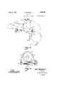
- Fig. 2 is a view in section through the turbine and associated heater
- Fig. 1 is a diagrammatic representation of a condensing steam turbine plant equipped with a feed water heating system in accordance with the invention
- Fig. 2 is a view in section through the turbine and associated heater
- Fig. 1 is a diagrammatic representation of a condensing steam turbine plant equipped with a feed water heating system in accordance with the invention
- Fig. 2 is a view in section through the turbine and associated heater
- Fig. 1 is a diagrammatic representation of a condensing steam turbine plant equipped with a feed water heating system in accordance with the invention
- Fig. 2 is a view in section through the turbine and associated heater
- Fig. 1 is a diagrammatic representation of a condensing steam turbine plant equipped with a feed water heating system in accordance with the invention
- FIG. 3 is aview in section on line IIIIII of Fig.2; and Fig. 4 is a diagrammatic representation of a condensing steam turbine plant illustrating a modified form of my invention.
- the plant illustrated comprises a turblne 1, condenser 2, hot-well 3, extraction pump 4, feed water heaters 5, 6, 7 and '8, and an evaporator 9.
- steam is supplied to the turbine 1 through a condult 71 by a boiler 72.
- the feed water heaters 5, 6, 7 and 8 are connected in series in the order named between the extraction pump 4 and the feed pump (not shown) by pipes 10, 11, 12, 13 and 14 and on the steam side the first mentioned feed water heater is connected with the steam space of the evaporator 9 by a pipe 15 and with the hot well by a drain 16 controlled by a valve 17, while the remainder are connected with operative stages of the turbine 1 by bleeder connections, illustrated in connection with the heaters 7 and 8 only where they are designated by the numerals 18 and 19, and with the condenser by drain pipes shown in connection with the heaters 6, 7 and 8 and designated by the numeral 20.
- the steam space of the heater 6 is further connected by a pipe 21 controlled by a valve 22 with the steam space of the evaporator 9, this latter being also connected with the hot well by a drain pipe 23.
- a make-up water supply pipe 25 leads to the evaporator 9, the supply being suitably controlled by a valve 26 operated by a fioat27.
- the heater 6 as illustrated is of a type disclosed in my Patent No. 1,342,841, granted June 8, 1920, and assigned to the Westinghouse Electric and Manufacturing Company.
- a steam chest or belt 33 surrounds the turbine cylinder and communicates with the latter through a series of slots 34 through which a portion of the steam flowing through an operatiye low pressure stage of the turbine passes into the belt 33.
- the lower half of the steam chest or belt is extended to form a compartment 35 for the reception of the feed heater 6 which is of the surface type.
- the heater tubes are indi cated at 37 and are provided at either end with water boxes 38, 39 to form a multiple pass heater of well known construction.
- water boxes 38 and 39 are attached to the facings 40 and 41, respectively, formed in the lower portion of the extension 35 of the steam chest or belt 33.
- the pipes for conducting the condensate to be heated to and from the heater 6 are shown at 11 and 12, respectively.
- the drain 20 leads from the bottom and the conduit 21 for conveying steam to the evaporator 9 leads from the side of the heater com- .partment 35.
- Condensate from the extraction pump passes through the heaters 5, 6, 7 and 8 in the order stated where it is heated progressively first by steam generated from the make-up water in the evaporator and then by steam at different degrees of expansion tapped from operative stages of the turbine, water condensed in the evaporator and in the several feed water heaters being drained away to the hot well in the usual manner.
- the plant illustrated in Fig. 4 comprises a boiler 72, a steam turbine 1, condenser 2,
- the heaters 44 and 45 are connected in parallel between the extraction pump 4 and the boiler feed pump (not shown) by pipes 46, 47 48, 49, 50 and 51 and on their steam sides they are connected with an operative stage of the turbine 1 and the water space of the evaporator 52 by pipes 53 and 54, respectively.
- Valves 55 and 56 are provi-ded in the pipes 48 and 50, respectively; the steam space of the evaporator 52 is connected with a higher pressure operative stage of the turbine 1 by a pipe 57 controlled by avalve 58, anddrains "59 and 60, the latter controlled by a valve 61, connect the steam spaces ofthe feed water heaters 44 and 45 and the condenser 2.
- a power plant the combination with a multi-stage steam turbine and a condenser for receiving the exhaust steam therefrom, first and second heaters, an evaporator, means for extracting steam from the turbine and for utilizing said steam as a heating agent in the first heater and then as a heating agent in the evaporator, a second heater, means for conveying the vapor generated in the evaporator as a heating agent to the second heater, and means for conveying feed water to be heated to the second heater and thence to the first heater.
Landscapes
- Engineering & Computer Science (AREA)
- Mechanical Engineering (AREA)
- General Engineering & Computer Science (AREA)
- Engine Equipment That Uses Special Cycles (AREA)
Description
K. BAUMANN April 5, 1932.
CONDENSER Filed April 10, 1924 '2 Sheets-Sheet l For! Bavmann INVENTOR v ATTORNEY April 5, 1932. K, BAUMANN 1,852,640
CONDENSER Filed April 10 1924 2 Sheets-Sheet 2 F I I lfar/ Baumann WITNESS INVENTOR ATTORN EY Patented Apr. 5, 1932 UNITED STATES I KARL BAUMANN, OF URMSTON, ENGLAND, ASSIGNOR TO WESTINGHOUSE ELECTRIC & r
PATENT OFFICE MANUFACTURING COMPANY, A CORPORATION OF PENNSYLVANIA CONDENSER Application filed April 10, 1924, Serial No. 705,646, and in Great Britain Apri1 11, 1923.
This invention relates to condensing steam turbine plants in which the make-up water for the boilers is passed through an evaporator before admission to the circulatory system of the plant. I
The object of the present invention is to provide a power plant of the aforesaid type in Which the final temperature of the feed water will not be directly dependent upon the supply of steam from the evaporator. To this end, in accordance with the invention, a separate feed water heater is provided for condensing and utilizing the heat contained in the steam generated in the evaporator. 7 The feed water heater is disposed either before any heater which is supplied with steam from an operative stage of the turbine or is arranged to constitute the rimary heater of a progressive feed Water eating system. By this means the final temperature of the feed water is dependent upon the last heater of the system; Consequently it is only necessary to provide one feed water heater after the heater which is supplied with steam from Q." the evaporator and, when this heater is supplied withsteam from an operative stage of the turbine, only one tapping from the turbine, although of course any number of heaters may be employed depending upon the usual considerations for any particular plant. 1 In order that the invention may be more clearly understood and readily carried into practice reference will now be made to the accompanying drawings in which Fig. 1 is a diagrammatic representation of a condensing steam turbine plant equipped with a feed water heating system in accordance with the invention; Fig. 2 is a view in section through the turbine and associated heater; Fig. 3 is aview in section on line IIIIII of Fig.2; and Fig. 4 is a diagrammatic representation of a condensing steam turbine plant illustrating a modified form of my invention. v The plant illustrated comprises a turblne 1, condenser 2, hot-well 3, extraction pump 4, feed water heaters 5, 6, 7 and '8, and an evaporator 9. As is customary, steam is supplied to the turbine 1 through a condult 71 by a boiler 72. On the water side the feed water heaters 5, 6, 7 and 8 are connected in series in the order named between the extraction pump 4 and the feed pump (not shown) by pipes 10, 11, 12, 13 and 14 and on the steam side the first mentioned feed water heater is connected with the steam space of the evaporator 9 by a pipe 15 and with the hot well by a drain 16 controlled by a valve 17, while the remainder are connected with operative stages of the turbine 1 by bleeder connections, illustrated in connection with the heaters 7 and 8 only where they are designated by the numerals 18 and 19, and with the condenser by drain pipes shown in connection with the heaters 6, 7 and 8 and designated by the numeral 20. The steam space of the heater 6 is further connected by a pipe 21 controlled by a valve 22 with the steam space of the evaporator 9, this latter being also connected with the hot well by a drain pipe 23. A make-up water supply pipe 25 leads to the evaporator 9, the supply being suitably controlled by a valve 26 operated by a fioat27.
The heater 6 as illustrated is of a type disclosed in my Patent No. 1,342,841, granted June 8, 1920, and assigned to the Westinghouse Electric and Manufacturing Company. As shown in Figs. 2 and 3, a steam chest or belt 33 surrounds the turbine cylinder and communicates with the latter through a series of slots 34 through which a portion of the steam flowing through an operatiye low pressure stage of the turbine passes into the belt 33. The lower half of the steam chest or belt is extended to form a compartment 35 for the reception of the feed heater 6 which is of the surface type. The heater tubes are indi cated at 37 and are provided at either end with water boxes 38, 39 to form a multiple pass heater of well known construction. The
to the plant by Way of the evaporator 9 through the connection 25. Condensate from the extraction pump passes through the heaters 5, 6, 7 and 8 in the order stated where it is heated progressively first by steam generated from the make-up water in the evaporator and then by steam at different degrees of expansion tapped from operative stages of the turbine, water condensed in the evaporator and in the several feed water heaters being drained away to the hot well in the usual manner.
With this arrangement a relatively high vacuum will be created in the feed water heat er 5 owing to the relatively low temperature of the water admittedthereto and as a result of this the evaporation of the'inake-up water in the evaporator 9 will be effected at a relatively low temperature and any scale formed in the latter will be softer and more readily removed than if evaporation were effected at a higher temperature. Furthermore, the steam used for effecting evaporation is itself at a relatively low temperature, having been utilized both for the production of mechanical work in the turbine 1 and for feed water heating in the heater 6 before its admission to the evaporator 9. Consequently a relatively high thermal efficiency is obtainable. Should priming take place in the evaporator 9 no water therefrom can enter the turbine and when it is desired to isolate the evaporator from the plant it is only necessary to close one relatively large valve 22 and one relatively small valve 17.
It will also be apparent that with this arrangement the final temperature of the feed water is not directl dependent upon the steam supply from the evaporator and that although any number of heaters may be provided, as may be determined by the usual considerations, satisfactory operation can be obtained if only a single heater is installed after the heater (5) which is supplied with steam from the evaporator.
The plant illustrated in Fig. 4 comprises a boiler 72, a steam turbine 1, condenser 2,
hot well 3 and extraction pump 4, as in Fig. 1, and feed water heaters 44 and 45, and evaporator 52. On their water sides the heaters 44 and 45 are connected in parallel between the extraction pump 4 and the boiler feed pump (not shown) by pipes 46, 47 48, 49, 50 and 51 and on their steam sides they are connected with an operative stage of the turbine 1 and the water space of the evaporator 52 by pipes 53 and 54, respectively. Valves 55 and 56 are provi-ded in the pipes 48 and 50, respectively; the steam space of the evaporator 52 is connected with a higher pressure operative stage of the turbine 1 by a pipe 57 controlled by avalve 58, anddrains "59 and 60, the latter controlled by a valve 61, connect the steam spaces ofthe feed water heaters 44 and 45 and the condenser 2.
-water space of the evaporator 52, respectively, and from thence to the feed pump by way of pipe 51.
This arrangement, in addition to affording the advantages of the previously described arrangement as regards the provision of only one large air tight valveand the prevention of access to the turbine of any water which may pass over from the evaporator due to priming, readily permits of the complete isolation of the evaporator 52 and the feed heater 45, which can be effected by simply closing the valves 55, 56, 58 and 61. When the evaporator 52 and feed water heater 45 are isolated from the plant the whole of the feed water will flow through the heater 44 the heat transference in which will automatically increase in proportion to the quantity of Water flowing therethrou 'gh.
Although in the plant illustrated in this figure only two feed water heaters are shown it will be apparent that any desired number may be provided, it being only necessary that the heater which is heated by the evaporator be connected on its water sidein parallel with a heater which is heated from any other source. 7
While I have shown my invention in but two forms, it will be obvious to those skilled in the art that it is not so limited, but is susceptible of various other changes and modifications, without departing from the -spirit thereof, and I desire, therefore, that only such limitations shall be placed thereupon as are imposed by the prior art or as are specifically set forth in the appended claims.
What I claim is: y W
1. In a power plant, the combination with a multi-stage steam turbine and a condenser for receiving the exhaust steam therefrom, first and second heaters, an evaporator, means for extracting steam from the turbine and for utilizing said steam as a heating agent in the first heater and then as a heating agent in the evaporator, a second heater, means for conveying the vapor generated in the evaporator as a heating agent to the second heater, and means for conveying feed water to be heated to the second heater and thence to the first heater. V
2. In a power plant,'the=c'ombination with a multi-stage steam turbine and a condenser for receiving the exhaust steam therefrom, of first and second heaters, an' evaporat'or, means for extracting steam at a sub atmospher'ic pressure from the turbine and for supplyin said steam as a heating agent to 'the'first heater and thence as a heating agent to the evaporator, means for conveymg the vapor generated in the evaporator as a heating agent to the second heater, and means for conveying feed water to be heated to the second heater and thence to the first heater.
3. In a power plant, the combination with a multi-stage steam turbine and a condenser for receiving the exhaust steam therefrom, of first, second and third heaters, an evaporator, means for extracting relatively high pres sure steam from the turbine and for supplying said steam as a heating agent to the first heater, means for extracting relatively low pressure steam from the turbine and for supplying said steam as a heating agent to the second heater and thence as a heating agent to the evaporator, means for supplying vapor generated in the evaporator as a heating agent to the third heater, and means for conveying feed water to be heated through the third, second and first heaters in series.
In testimony whereof, I have hereunto subscribed my name this 27th day of February,
KARL BAUMANN.
Applications Claiming Priority (1)
| Application Number | Priority Date | Filing Date | Title |
|---|---|---|---|
| GB1852640X | 1923-04-11 |
Publications (1)
| Publication Number | Publication Date |
|---|---|
| US1852640A true US1852640A (en) | 1932-04-05 |
Family
ID=10891999
Family Applications (1)
| Application Number | Title | Priority Date | Filing Date |
|---|---|---|---|
| US705646A Expired - Lifetime US1852640A (en) | 1923-04-11 | 1924-04-10 | Condenser |
Country Status (1)
| Country | Link |
|---|---|
| US (1) | US1852640A (en) |
Cited By (2)
| Publication number | Priority date | Publication date | Assignee | Title |
|---|---|---|---|---|
| US2707239A (en) * | 1948-12-20 | 1955-04-26 | Frederick W Richl | Apparatus for utilizing waste heat |
| US2982102A (en) * | 1958-05-12 | 1961-05-02 | Sulzer Ag | Steam power system |
-
1924
- 1924-04-10 US US705646A patent/US1852640A/en not_active Expired - Lifetime
Cited By (2)
| Publication number | Priority date | Publication date | Assignee | Title |
|---|---|---|---|---|
| US2707239A (en) * | 1948-12-20 | 1955-04-26 | Frederick W Richl | Apparatus for utilizing waste heat |
| US2982102A (en) * | 1958-05-12 | 1961-05-02 | Sulzer Ag | Steam power system |
Similar Documents
| Publication | Publication Date | Title |
|---|---|---|
| US2982864A (en) | Improved heat cycle for power plants | |
| US2900792A (en) | Steam power plant having a forced flow steam generator | |
| US3016711A (en) | Steam turbine power plant | |
| US3183896A (en) | Separating heater | |
| US3537265A (en) | Apparatus for condensing sealing fluid from gland structures | |
| US3032999A (en) | Steam turbine power plants | |
| US1852640A (en) | Condenser | |
| US1781368A (en) | Power plant | |
| US3173267A (en) | Steam cycle in which more than two stages of feed water heating are carried out by one exhaust steam system from auxiliary turbine | |
| US1732009A (en) | Method and apparatus for development of power | |
| US1509782A (en) | Feed-water heater | |
| US1889307A (en) | System of reheating in a power plant | |
| US1712992A (en) | Turbine locomotive | |
| US1703093A (en) | Evaporator and preheater system | |
| US2924074A (en) | chambadal etal | |
| US1954823A (en) | Steam turbine system | |
| US1897815A (en) | Power plant | |
| US1895220A (en) | Method of vaporizing | |
| US1400935A (en) | High-heat-level evaporator system | |
| US1846047A (en) | Evaporator system | |
| US2086781A (en) | Power plant | |
| US1945581A (en) | Oil refining | |
| US1804616A (en) | Multistage feed water heating | |
| US3504495A (en) | Multiple reheating apparatus for steam turbines | |
| US1304144A (en) | Karl baumann |