US1852601A - Expanding internal milling machine - Google Patents
Expanding internal milling machine Download PDFInfo
- Publication number
- US1852601A US1852601A US429487A US42948730A US1852601A US 1852601 A US1852601 A US 1852601A US 429487 A US429487 A US 429487A US 42948730 A US42948730 A US 42948730A US 1852601 A US1852601 A US 1852601A
- Authority
- US
- United States
- Prior art keywords
- shaft
- cutters
- pipe
- milling machine
- expanding internal
- Prior art date
- Legal status (The legal status is an assumption and is not a legal conclusion. Google has not performed a legal analysis and makes no representation as to the accuracy of the status listed.)
- Expired - Lifetime
Links
- 238000003801 milling Methods 0.000 title description 11
- 238000006073 displacement reaction Methods 0.000 description 3
- 238000010276 construction Methods 0.000 description 1
- 230000003247 decreasing effect Effects 0.000 description 1
- 239000012530 fluid Substances 0.000 description 1
- 230000008520 organization Effects 0.000 description 1
- XLYOFNOQVPJJNP-UHFFFAOYSA-N water Substances O XLYOFNOQVPJJNP-UHFFFAOYSA-N 0.000 description 1
Images


Classifications
-
- B—PERFORMING OPERATIONS; TRANSPORTING
- B23—MACHINE TOOLS; METAL-WORKING NOT OTHERWISE PROVIDED FOR
- B23C—MILLING
- B23C3/00—Milling particular work; Special milling operations; Machines therefor
- B23C3/28—Grooving workpieces
- B23C3/34—Milling grooves of other forms, e.g. circumferential
-
- Y—GENERAL TAGGING OF NEW TECHNOLOGICAL DEVELOPMENTS; GENERAL TAGGING OF CROSS-SECTIONAL TECHNOLOGIES SPANNING OVER SEVERAL SECTIONS OF THE IPC; TECHNICAL SUBJECTS COVERED BY FORMER USPC CROSS-REFERENCE ART COLLECTIONS [XRACs] AND DIGESTS
- Y10—TECHNICAL SUBJECTS COVERED BY FORMER USPC
- Y10T—TECHNICAL SUBJECTS COVERED BY FORMER US CLASSIFICATION
- Y10T29/00—Metal working
- Y10T29/49—Method of mechanical manufacture
- Y10T29/496—Multiperforated metal article making
-
- Y—GENERAL TAGGING OF NEW TECHNOLOGICAL DEVELOPMENTS; GENERAL TAGGING OF CROSS-SECTIONAL TECHNOLOGIES SPANNING OVER SEVERAL SECTIONS OF THE IPC; TECHNICAL SUBJECTS COVERED BY FORMER USPC CROSS-REFERENCE ART COLLECTIONS [XRACs] AND DIGESTS
- Y10—TECHNICAL SUBJECTS COVERED BY FORMER USPC
- Y10T—TECHNICAL SUBJECTS COVERED BY FORMER US CLASSIFICATION
- Y10T409/00—Gear cutting, milling, or planing
- Y10T409/30—Milling
- Y10T409/304424—Means for internal milling
-
- Y—GENERAL TAGGING OF NEW TECHNOLOGICAL DEVELOPMENTS; GENERAL TAGGING OF CROSS-SECTIONAL TECHNOLOGIES SPANNING OVER SEVERAL SECTIONS OF THE IPC; TECHNICAL SUBJECTS COVERED BY FORMER USPC CROSS-REFERENCE ART COLLECTIONS [XRACs] AND DIGESTS
- Y10—TECHNICAL SUBJECTS COVERED BY FORMER USPC
- Y10T—TECHNICAL SUBJECTS COVERED BY FORMER US CLASSIFICATION
- Y10T409/00—Gear cutting, milling, or planing
- Y10T409/30—Milling
- Y10T409/306664—Milling including means to infeed rotary cutter toward work
- Y10T409/306776—Axially
- Y10T409/307168—Plural cutters
Definitions
- My invention relates to an expanding internalmilling machin-e of the type particularly adapted for cutting a plurality of lon. gitudinal, staggered, outwardly tapering A 5 Slots in a pipe to form a strainer for use in wells.
- pipe strainers for wells should have longitudinal', preferably staggered, and necessarily outry, wardlyV tapering slots therein so as to permit maximum flow of water or other fluid without clogging of the slots.
- a further obj ect of the invention is to produce a milling device of this general character which will cut a plurality of longitudinal, outwardly tapering slots simultaneously and in any desired arrangement.
- a still further object ofmy invention is to produce a novel expanding internal mill-V ing machine which can be operated at a dis#V tance regardless of the length of the pipe being slotted, and whereby slotted pipe strainers in lengths not heretofore obtainable may be produced by a single continuous op eration and without any necessity of transversely cutting the pipe being slotted into smaller sections, which after being internal-v ly slotted by machines heretofore known. and used are subsequently joined together to form the necessary length.
- my invention consists of a. shaft of any desiredlength, means for driving said shaft, a driving gear carried by the front free end of the shaft, a plurality ⁇ of jaws or frame members carried by the front end of said shaft, sets of cutters carried by said jaws, driving connections from said "9* shaft to said cutters, means for actuating said jaws and cutters radially towards and away from said shaft, and driving connections for said last mentioned means extending longitudinally of said shaft.
- My invention further consists of the varions novel features of construction and advantage which are illustrated in the annexed drawings and which are. hereinafter Vdescribed and finally claimed.
- Fig. l represents a perspective view of an expanding internal milling machine embodying my invention.
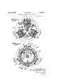
- l ⁇ Fig. 2 represents a section on line 2 2 of Fig. 3 represents a section on line 3 3 of Fig. 2.
- a Fig. 4 represents a section on line 4 4 of Fig. 3.
- Fig. 5 represents a section on line 5 5 of Fig. 3.
- Fig. 6 represents a section von line 6 6 of Fig 3. Y
- Fig. 7 represents a fragmentary cross-sectional view of a pipe slotted by means ofthe machine shown in Fig. l. y
- Fig'. 8 represents the inside plan view of Fig. 7
- the fast cog wheel 5 is in mesh with or engages the cog wheel or gear 8 on the vertical shaft 9 to revolve the latter when the shaft 1 is driven or revolved.
- the cog wheel 8 is loose on tl e shaft 9 and .is keyed thereto as at 9m, thereby serving to rotate the shaft 9 without preventing the vertical displacement thereof;
- the shaft 9 is provided with the worm 10 which engages the gear 12 fast on the transverse shaft 13 to revolve the latter.
- the shaft 13 carries a pair of parallel, spaced, bevelled cutters 15 which are revolved by the rotation of the shaft 9 which in turn is actuated by the rotation of the shaft 1-
- the shaft 9 is provided with anti-friction means 11, best seen in Fig. 3.
- I employ threevshafts 13 each carrying a pair of parallel, spaced, bevelled cutters 15, each of said shafts 13 being actuated by a corresponding shaft 9 having a worm 10 which engages a gear 12, and a gear 8 which engages the driving gear 5 on the front end of the shaft 1, so that six cutters are simultaneously actuated from the single shaft 1.
- the cog wheel 21 is provided on the opposite face thereof withthe spiral rib 22 which engages the'toothed racks 24'.
- ⁇ 'Each rack '24 is carried by or for-ms part of the frame or jaw 25, which carries a shaft 9, a shaft 18, a pair of cutters 15, and their adjuncts so that by rotation of the pinions 20 (or any of them) and the rotation of the cog wheel 21, the various pairs of cutters 15 are actuated radially with respect to the shaft 1.
- I provide suitable anti-friction means 26, best seen in Fig. 3-
- the pinions 2O may be actuated by any suitable socket wrench engaging the stems 27 thereof, as will be understood from Fig. 1.
- the shaft 30 which carries the worm 31 which engages one of the pinions 20, whereby the cog wheel 21 may be revolved to actuate the racks 24 radially towards or away from the shaft l.
- the shaft 30 may be manually operated at its rear or outer end, or it may be geared to the shaft 1 or to any other driving means or connection.
- the expansible or radially movable cutters 15, together with their movable supports, driving means and other adjuncts, are enclosed or assembled between front and rear plates 32 and 33 which are engaged by the bolts 34, as will be understood from the drawings.
- the entire milling machine With the cutters 15 in their innermost positions, that is, when the cutters are nearest to the reduced portion 2 of the shaft 1, the entire milling machine is inserted into the pipe 18 to be slotted.
- the shaft 1 is then revolved to revolve the cutters 15 and the pinions 20 are manipulated by the shaft 30 or manually by a socket Wrench to raise or move the cutters 15 radially away from the longitudinal median line ofthe milling machine, thereby bringing the edges of the cutters linto effective contact with the surface of the pipe 18.
- the pinions 20 are gradually turned further to raise the cutters 15 until a through ⁇ slot of the desired dimensions has been cut in the pipe.
- An internal pipe milling machine for cutting outwardly tapering longitudinal slots, comprising a main driving shaft adapted to extend within the pipe to be slotted, a plurality of intermediate shafts disposed radially with respect to said main driving shaft, driving connections intermediate said main CII
Landscapes
- Engineering & Computer Science (AREA)
- Mechanical Engineering (AREA)
- Turning (AREA)
Description
April 5, 1932. E, G. BOYER EXPANDING INTERNAL MILLING MACHINE Filed Feb. 19, 1930 5 Sheets-Sheet /ZVVE/VTOR. {AWM-50 ATTORNEY April 5, 1932. E. G. BOYER 1,852,601
EXPANDING INTERNAL MILLING MACHINE V Filed Feb. 19, 1930 s sheets-sheet 2 ATTORNEY 1930 3 Sheets-Sheet 5 ..nn\n
E. G. BOYER EXPANDING INTERNAL MILLlING MACHINE` Filed Feb. 19,
April 5; 1932.
ATTORNEY Patented Apr. 5, 1932 PATENT OFFICE EARL-E G. ZBOYR, OF PHILADELPHIA,PENNSYLVANIA nx'rANDING' INTERNAL MILLING MACHINE Application filed February 19, 1930. YSerial No. 429,487. i
My invention relates to an expanding internalmilling machin-e of the type particularly adapted for cutting a plurality of lon. gitudinal, staggered, outwardly tapering A 5 Slots in a pipe to form a strainer for use in wells.
As is well lmown, it is desirable that pipe strainers for wells should have longitudinal', preferably staggered, and necessarily outry, wardlyV tapering slots therein so as to permit maximum flow of water or other fluid without clogging of the slots.
It is therefore the object of my invention to produce a novel expanding internal milling machine wherebyv pipe strainers of any desired length may be cut orslotted efficiently, economically, and exeditiously, from the inside of the pipe being cut, and whereby the slots thus produced are of an outwardly tapering character and extend longitudinally of the pipe.
A further obj ect of the invention is to produce a milling device of this general character which will cut a plurality of longitudinal, outwardly tapering slots simultaneously and in any desired arrangement.
A still further object ofmy invention is to produce a novel expanding internal mill-V ing machine which can be operated at a dis#V tance regardless of the length of the pipe being slotted, and whereby slotted pipe strainers in lengths not heretofore obtainable may be produced by a single continuous op eration and without any necessity of transversely cutting the pipe being slotted into smaller sections, which after being internal-v ly slotted by machines heretofore known. and used are subsequently joined together to form the necessary length. I
To the above ends, my invention consists of a. shaft of any desiredlength, means for driving said shaft, a driving gear carried by the front free end of the shaft, a plurality `of jaws or frame members carried by the front end of said shaft, sets of cutters carried by said jaws, driving connections from said "9* shaft to said cutters, means for actuating said jaws and cutters radially towards and away from said shaft, and driving connections for said last mentioned means extending longitudinally of said shaft.
My invention further consists of the varions novel features of construction and advantage which are illustrated in the annexed drawings and which are. hereinafter Vdescribed and finally claimed.
In the accompanying drawings:
Fig. l represents a perspective view of an expanding internal milling machine embodying my invention. l`Fig. 2 represents a section on line 2 2 of Fig. 3 represents a section on line 3 3 of Fig. 2. A Fig. 4 represents a section on line 4 4 of Fig. 3. l
Fig. 5 represents a section on line 5 5 of Fig. 3.
Fig. 6 represents a section von line 6 6 of Fig 3. Y
Fig. 7 represents a fragmentary cross-sectional view of a pipe slotted by means ofthe machine shown in Fig. l. y
Fig'. 8 represents the inside plan view of Fig. 7
For the purpose, of illustrating my invention I have shown in the accompanying ldrawings one form thereof which is at present preferred by me, since the same has been found in practice to give satisfactory and reliable results, although Ait is to be understood that the various instrumentalities of which my invention consists can be variously arranged and organized and that my invention is not limited to the precise arrangement and organization of the instrumenta-Eties as herein shown and described.
Referringto` the drawings, in which similar niunerals of reference indicate corres ending parts, and referring particularly to ig. 3, 1
carries the front fast cog wheel or gear 5, and
the rear loose cog wheel or gear 6. The fast cog wheel 5 is in mesh with or engages the cog wheel or gear 8 on the vertical shaft 9 to revolve the latter when the shaft 1 is driven or revolved. The cog wheel 8 is loose on tl e shaft 9 and .is keyed thereto as at 9m, thereby serving to rotate the shaft 9 without preventing the vertical displacement thereof; The shaft 9 is provided with the worm 10 which engages the gear 12 fast on the transverse shaft 13 to revolve the latter. The shaft 13 carries a pair of parallel, spaced, bevelled cutters 15 which are revolved by the rotation of the shaft 9 which in turn is actuated by the rotation of the shaft 1- The shaft 9 is provided with anti-friction means 11, best seen in Fig. 3.
By reference to Figs. 1, 2,5, and 6, it will be seen that I employ threevshafts 13 each carrying a pair of parallel, spaced, bevelled cutters 15, each of said shafts 13 being actuated by a corresponding shaft 9 having a worm 10 which engages a gear 12, and a gear 8 which engages the driving gear 5 on the front end of the shaft 1, so that six cutters are simultaneously actuated from the single shaft 1.
While I have shown three pairs of cutters and the means to actuate the same simultaneously, it is to be understood that the number of cutters may be increased or decreased as desired. v In order to bring the cutters 15 into gradual effective contact with the inside surface of the pipe 18 (see Figs. 5, 6, 7, and`8) to be slotted, I provide the bevelled pinions 20 (preferably three in number) which engage the cog wheel 21, which is loose on the shaft 1. The cog wheel 21 is provided on the opposite face thereof withthe spiral rib 22 which engages the'toothed racks 24'.` 'Each rack '24 is carried by or for-ms part of the frame or jaw 25, which carries a shaft 9, a shaft 18, a pair of cutters 15, and their adjuncts so that by rotation of the pinions 20 (or any of them) and the rotation of the cog wheel 21, the various pairs of cutters 15 are actuated radially with respect to the shaft 1. To facilitate the radial displacement of the jaws or frames 25, I provide suitable anti-friction means 26, best seen in Fig. 3- The pinions 2O may be actuated by any suitable socket wrench engaging the stems 27 thereof, as will be understood from Fig. 1.
In order to actuate the cutters 15, when the cutting machine has advanced considerably within a relatively longpipe 18, and the stems 27` of the pinions 20 are no longer accessible for manual operation, I provide the shaft 30, which carries the worm 31 which engages one of the pinions 20, whereby the cog wheel 21 may be revolved to actuate the racks 24 radially towards or away from the shaft l. The shaft 30 may be manually operated at its rear or outer end, or it may be geared to the shaft 1 or to any other driving means or connection. To insure lateral alignment of the cutters 15 I provide the cog wheel 6 which is loose on the reduced portion 2 of the shaft 1 and which engages the cogs or gears 8 loose on the bottom of the shafts 9, thereby preventing the lateral displacement of the shafts 9 and their adjuncts.
yIn Figs. 6 and 7 I have shown samples of a pipe 18 slotted by a machine embodying my invention, illustrating the outwardly tapering characterof the slots formed by the cutters 15, it being understood that the length, arrangement, and number of slots in any given length of pipe may be varied at will without departing from the spirit or scope of the invention.
The expansible or radially movable cutters 15, together with their movable supports, driving means and other adjuncts, are enclosed or assembled between front and rear plates 32 and 33 which are engaged by the bolts 34, as will be understood from the drawings.
The operation is as follows:
With the cutters 15 in their innermost positions, that is, when the cutters are nearest to the reduced portion 2 of the shaft 1, the entire milling machine is inserted into the pipe 18 to be slotted. The shaft 1 is then revolved to revolve the cutters 15 and the pinions 20 are manipulated by the shaft 30 or manually by a socket Wrench to raise or move the cutters 15 radially away from the longitudinal median line ofthe milling machine, thereby bringing the edges of the cutters linto effective contact with the surface of the pipe 18. As the cutting progresses, the pinions 20 are gradually turned further to raise the cutters 15 until a through `slot of the desired dimensions has been cut in the pipe. The pinions 2O are then turned in the reverse direction to withdraw or retract the cutters 15 until they clear the inside surface of the pipe 18, whereupon the milling machine is turned around, advanced, or retarded to cutv additional slots 31 at any desired point in the surface of the pipe. Having thus described my invention, what I claim as new, and desire to secure by Letters Patent,"is: Y
An internal pipe milling machine for cutting outwardly tapering longitudinal slots, comprising a main driving shaft adapted to extend within the pipe to be slotted, a plurality of intermediate shafts disposed radially with respect to said main driving shaft, driving connections intermediate said main CII
Priority Applications (1)
| Application Number | Priority Date | Filing Date | Title |
|---|---|---|---|
| US429487A US1852601A (en) | 1930-02-19 | 1930-02-19 | Expanding internal milling machine |
Applications Claiming Priority (1)
| Application Number | Priority Date | Filing Date | Title |
|---|---|---|---|
| US429487A US1852601A (en) | 1930-02-19 | 1930-02-19 | Expanding internal milling machine |
Publications (1)
| Publication Number | Publication Date |
|---|---|
| US1852601A true US1852601A (en) | 1932-04-05 |
Family
ID=23703456
Family Applications (1)
| Application Number | Title | Priority Date | Filing Date |
|---|---|---|---|
| US429487A Expired - Lifetime US1852601A (en) | 1930-02-19 | 1930-02-19 | Expanding internal milling machine |
Country Status (1)
| Country | Link |
|---|---|
| US (1) | US1852601A (en) |
Cited By (3)
| Publication number | Priority date | Publication date | Assignee | Title |
|---|---|---|---|---|
| US3568568A (en) * | 1966-08-15 | 1971-03-09 | Euratom | Apparatus for milling and drilling grooves or radial holes into the internal walls of tubes |
| US4826369A (en) * | 1984-11-17 | 1989-05-02 | Mactaggart Scott (Holdings) Ltd. | Apparatus for machining splines on a tubular member |
| US20140014381A1 (en) * | 2011-01-27 | 2014-01-16 | Roger Anda | Machining apparatus |
-
1930
- 1930-02-19 US US429487A patent/US1852601A/en not_active Expired - Lifetime
Cited By (3)
| Publication number | Priority date | Publication date | Assignee | Title |
|---|---|---|---|---|
| US3568568A (en) * | 1966-08-15 | 1971-03-09 | Euratom | Apparatus for milling and drilling grooves or radial holes into the internal walls of tubes |
| US4826369A (en) * | 1984-11-17 | 1989-05-02 | Mactaggart Scott (Holdings) Ltd. | Apparatus for machining splines on a tubular member |
| US20140014381A1 (en) * | 2011-01-27 | 2014-01-16 | Roger Anda | Machining apparatus |
Similar Documents
| Publication | Publication Date | Title |
|---|---|---|
| US2464390A (en) | Oil well casing scraper | |
| US1852601A (en) | Expanding internal milling machine | |
| US2049336A (en) | Strainer | |
| US1490493A (en) | Peeling machine | |
| US1457193A (en) | Device for perforating oil-well casings | |
| US1427064A (en) | Drill bit | |
| DE2458238A1 (en) | DRILLING PROCEDURES AND TOOL HOLDERS FOR USING SUCH PROCEDURE | |
| US412626A (en) | Machine for forming axle-journals | |
| US2070780A (en) | Slotting, perforating, and splining of tubes and the like | |
| US2248278A (en) | Method of forming conical shells | |
| US1391624A (en) | Trench-wall-supporting machine | |
| US2467030A (en) | Cutting tool | |
| US1245238A (en) | Cutter-head. | |
| US2312459A (en) | Method of making deep well screens | |
| DE432967C (en) | Process for connecting the cooling plate fins to the tubes of automobile radiators | |
| US2582521A (en) | Machine for mining tender stones or other mineral substances | |
| AT87166B (en) | Machine for removing layers of earth. | |
| US2041894A (en) | Broaching machine | |
| DE729738C (en) | Device for cutting glass rings from vertically positioned glass tubes | |
| US1529576A (en) | Screen pipe-cutting machine | |
| DE622749C (en) | Rock drill for underwater drilling | |
| DE414588C (en) | Bohrerfuehrung for the production of angular drill holes for blasting rock and Like. According to previously determined blasting directions | |
| DE601093C (en) | Fitting with sharp teeth to be driven into the base | |
| AT138666B (en) | Machine for folding and interleaving pre-folded strips of paper or papers. | |
| US1695513A (en) | Pipe-slotting machine |