US1852546A - Partition and the like - Google Patents
Partition and the like Download PDFInfo
- Publication number
- US1852546A US1852546A US361288A US36128829A US1852546A US 1852546 A US1852546 A US 1852546A US 361288 A US361288 A US 361288A US 36128829 A US36128829 A US 36128829A US 1852546 A US1852546 A US 1852546A
- Authority
- US
- United States
- Prior art keywords
- stud
- portions
- ears
- panels
- metal
- Prior art date
- Legal status (The legal status is an assumption and is not a legal conclusion. Google has not performed a legal analysis and makes no representation as to the accuracy of the status listed.)
- Expired - Lifetime
Links
- 238000005192 partition Methods 0.000 title description 21
- 108091006146 Channels Proteins 0.000 description 41
- 239000002184 metal Substances 0.000 description 35
- 210000005069 ears Anatomy 0.000 description 30
- 239000011505 plaster Substances 0.000 description 16
- 238000009435 building construction Methods 0.000 description 13
- 238000010276 construction Methods 0.000 description 12
- 238000004519 manufacturing process Methods 0.000 description 7
- 230000004308 accommodation Effects 0.000 description 5
- 239000000463 material Substances 0.000 description 5
- 101100460844 Mus musculus Nr2f6 gene Proteins 0.000 description 1
- 239000002131 composite material Substances 0.000 description 1
- 238000006073 displacement reaction Methods 0.000 description 1
- 210000003027 ear inner Anatomy 0.000 description 1
- PXUQTDZNOHRWLI-OXUVVOBNSA-O malvidin 3-O-beta-D-glucoside Chemical compound COC1=C(O)C(OC)=CC(C=2C(=CC=3C(O)=CC(O)=CC=3[O+]=2)O[C@H]2[C@@H]([C@@H](O)[C@H](O)[C@@H](CO)O2)O)=C1 PXUQTDZNOHRWLI-OXUVVOBNSA-O 0.000 description 1
- 239000004570 mortar (masonry) Substances 0.000 description 1
- 108010085990 projectin Proteins 0.000 description 1
- 125000006850 spacer group Chemical group 0.000 description 1
Images
Classifications
-
- E—FIXED CONSTRUCTIONS
- E04—BUILDING
- E04B—GENERAL BUILDING CONSTRUCTIONS; WALLS, e.g. PARTITIONS; ROOFS; FLOORS; CEILINGS; INSULATION OR OTHER PROTECTION OF BUILDINGS
- E04B2/00—Walls, e.g. partitions, for buildings; Wall construction with regard to insulation; Connections specially adapted to walls
- E04B2/84—Walls made by casting, pouring, or tamping in situ
- E04B2/842—Walls made by casting, pouring, or tamping in situ by projecting or otherwise applying hardenable masses to the exterior of a form leaf
- E04B2/845—Walls made by casting, pouring, or tamping in situ by projecting or otherwise applying hardenable masses to the exterior of a form leaf the form leaf comprising a wire netting, lattice or the like
-
- E—FIXED CONSTRUCTIONS
- E04—BUILDING
- E04F—FINISHING WORK ON BUILDINGS, e.g. STAIRS, FLOORS
- E04F13/00—Coverings or linings, e.g. for walls or ceilings
- E04F13/02—Coverings or linings, e.g. for walls or ceilings of plastic materials hardening after applying, e.g. plaster
- E04F13/04—Bases for plaster
-
- E—FIXED CONSTRUCTIONS
- E04—BUILDING
- E04B—GENERAL BUILDING CONSTRUCTIONS; WALLS, e.g. PARTITIONS; ROOFS; FLOORS; CEILINGS; INSULATION OR OTHER PROTECTION OF BUILDINGS
- E04B2/00—Walls, e.g. partitions, for buildings; Wall construction with regard to insulation; Connections specially adapted to walls
- E04B2/72—Non-load-bearing walls of elements of relatively thin form with respect to the thickness of the wall
- E04B2/723—Non-load-bearing walls of elements of relatively thin form with respect to the thickness of the wall constituted of gypsum elements
Definitions
- This invention has to do with certain improvements in partitions and the like for building construction.
- the invention relates to improvements in the means of bonding or 5 joining together the contiguous edges of partition sections, as well as improvements in means for insuring proper bond of the plaster or finished surface to the body of the partition itself.
- the features of the invention may also be used in connection with other portions of building construction, as, for example, the construction of the ceilings, and the construction of the furring for the inside finish of the outside walls. Therefore, I do not intend to limit myself to the use of the features of invention to partitions strictly speaking, but the features of the invention may also be used in connection with building construction generally.
- the main object of the invention is to provide an improved trussed metal stud for joining together the adjacent edge portions of the partition sheets, fin-ring, or other build ing constructions to be joined.
- This improved metal stud is of such construct-ion that the adjacent edges of the partition or the like may be easily set into the stud whereupon they will be brought to proper alignment with each other and firmly and accurately supported in such position.
- Another featiiire in connection with the foregoing is to form the stud of sheet metal which can be stamped out into the desired shape to receive the adjoining edges of the building panels.
- a feature of the invention relates to the provision of a stud having projecting portions together with openings in the body of the stud itself, so that the plaster or other surfacing material will penetrate into the openings and take hold of the projections and thus be very firmly and permanently held in place.
- the result will be that the entire structure will be reinforced and held together largely after the fashion of a trussed bridge structure, embedded in mortar.
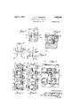
- FIG. 1 shows an edge view of a section of studding embodying the features of the present invention
- Figure 2 shows a view Figure 1
- Figure 3 shows a cross section on the line 33 of Figure 2, looking in the direction of the arrows;
- Figure 4 shows a cross section on the line l-4 of Figure 1, looking in the direction of the arrows; V
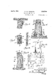
- Figure 5 shows a fragmentary face view of the lower portion of a completed partition embodying the features of the present invention, the base-board not being in place, and this figure shows how the portions of the base sections may be joined together by the studding;
- Figure 6 shows a fragmentary section of the upper portion of a wall and the adjacent portion of the ceiling, the face of the wall being cut away, and the figure shows the manner in which the upper end of the stud may be connected into the ceiling by means of a special clip;
- Figure 7 shows a detail enlarged view taken on the line 7-7 of Figure 6, looking in the direction of the arrows, to better illustrate the form of clip;
- Figure 8 shows a cross section on the line at right-angles to 88 of Figure 6, looking in the direction of the arrows;
- Figure 9 shows a horizontal section through a partition having the panels joined together by the stud of the present invention, the partition having been finished by plastering both faces;
- Figure 10 shows a cross section on the line 1010 of Figure 5, looking in the direction of the arrows;
- Figure 11 shows a' fragmentary face view of a section of lath partition having the lathe woven together by tie-wires
- Figure 12 shows a fragmentary section on the line 1212 of Figure '11, looking in the direction of the arrows;
- Figure 13 shows aface view .of a spreader for the base board construction; and I 1 Figure .14 shows across section through the-lower portion of a partition provided with. a metal base-board, the companion sheets or plates of which are spaced apart by Spreaders such as that shown. in Fig .u-re 13.
- the studding of the. present invention comprises a sheet of metal which is folded or bent into a channel shape as particularly shown in Figure 4. .
- the base portion itself is. regularly stamped out on both sides of the center or medial line so as to establish the relatively large openings 18 on one said-and 19 on the otherside.
- These openings reach around .partway-into the flanges 16 and 17 asbest shown in Figures 2 and 3,.but the edge portions of theflanges are left unsevered 111M. continuous. 1
- a certain amount of springiness or flexibility is present in'theseearsso that by proper design and form they may be caused to engage the edges of the partition sections with a gripping action.
- the ears can be bent or forced over against the panel so as to increase the gripping action.
- the ears can-be readil r bent in to en a e the o enin 's there- 5 b 7 D of in a definite manner.
- extensions 25 and 6 also facilitate the sliding of the panels into place and serve to more efiectively guide and support the panels with respect to the stud.
- edge portions 16 and 17 of the stud project somewhat beyond the surfaces of the panels when assembled as-shown in Fig. 9. These edge portions therefore serve to establish projections to which the plaster 28 may adhere. They also perform other functions which will be presently explained.
- the ears 20 and 21 as well as the projections 25 and 26' also reach outwardly and into the body of the plaster so as to establish other and numerousprojections to which the plaster will adhere.
- Figures 1 and 2 in particular shows the fact that the openings 18 and 10 are of an oval or elliptical form. opeuings are of similar form. The result is that the extensions .25 and 26 are wider-at iii-30 their extreme edges than at the points where they connect to the cars 20 and E21. Consequently, said extensions will much more e1"?- t'ectively adhere to the plaster because of their dove-tailing form. This fact readily apparent from a study of Figures 1 and 6.
- the projections and 26 may also be perforated as shown at 25).
- I provide a base strip 3.
- ct suitable composition material the lower edge of which rests upon the .tloor Ti upper edge of this has trip 32 is preferably grooved as show at 3stto receive the lower edge ol' he panel such as 31.
- the strip 32 has its upper portion of full width ot the partition including the plastering 28. As a consequencev the plaster maybe brought down flush with the surfaces thereof.
- the base strips 32 are of reduced or tapered thickness in alignment with the positions of the studding strips. These reduced thicknes s are shown at 35 in Figure 5. These portions 35 are thus brought down to the same thickness as the panels 30 and 31. By this means the studding can be carried down low enough to join together the end portions of the base strips 32 as shown in Figure 5.
- the faces of the base strips are recessed or grooved shown at 35. This will establish longitudinal extending: channels tor the accommodation of electric wires or other utilities to be placed therein.
- the base-boards 37 when in place will cover over these channels and any wires or utilities contained therein.
- stl'lddingrs may he surmorted in any convenient manner.
- a clip such as 38 may be provided, the lower portion of which enga the upper end of the stud, the upper portion of said clip being: embedded within the ceiling 39, as shown in Figure 6 for example.
- lt is of U shape to coi'rtorm generally to the channel portion of the stud.
- the lower portion of the clip is provided with a central downwardly depending; prong 40 which enters into the space such as 23 at the 1 l or convex side of the stud, and the extreme edges of the clip are provided withears 41 and 42 which reach down at the sides of the stud.
- the clip is also provided with other cars 4:3 and all; which extend down within the concave portion of the stud and adjacent to the flanges 16 and 17 thereof.
- the upper end of the clip 38 is preferably corrugated or pointed as shown at 45 in Figures 6 and 7.
- FIGs 11 and 12 show another form of panel which can be conveniently used in conjunction with studs of the present invention.
- This panel comprises the laths l5 and 46 which are woven together by the Wires l? on one side and 48 on the other side. These wires are periodically interlooped together as shown in Figure 12 at points between the lathe. In this way the panel is of open work construction so that the plaster can extend clear through between the laths.
- Figure 14 l have shown a modified con struction of the base.
- the base comprises a pair of companion sheet metal strips 49.
- the upper portions of these strips are folded inwardly towards each other and downwardly on a slight slant as shown at 50, and the extreme inner edges of these portions are then turned up to parallel flanges 51.
- the strips 4C9 and 50 are set into place they are "so spaced that the flanges 50 and 51 may accommodate the lower ed go of the panel such as 31 between them.
- the portions 50 establish grounds for the lower edges of the plastering 28 which can be finished oil flush therewith.
- the lower edges of the strips 49 are also turned inwardly towards each other and up wardly on a slight slant as shown at 52, and the extreme edges of these portions are then carried straight up and folded backwards slightly as shown at 53 to establish hook portions.
- Spacing plates such as 54 are periodically located throughout the length of this base s ructure.
- the upper corners 55 and 56 of these plates 5 are formed to correspond with the portions 50 of the strips 49 so as to engage and support said portions.
- the plates 54 are provided with central out-Ward projections 57 and 58 which serve to contact and properly space the strips 49.
- the lower portions of the plates 54 are provided with upwardly extending notches 59, the extreme. upper ends of which are enlarged as shown in l ia'ure 13 so as to receive the hooked edges 53 already referred to. Tie result is that by proper manipulation the strips ll) may be first engaged with and hooked into the lower portions of the plates 54-, after which the upper portions of the strips 4:9 may be torced over and engaged with the upper corner portions 55 and 56 of plates When the plates 54% are thus set into place their lower portions 60 will coo-perateaviththeir upper corner portions'55 and, 56 to maintain the spacer plates 54 firmlyin place.
- the lower corners 61 of the plates'5t may be cut-away if desired seas to'accommodate wooden. strips 62 set along: the lower corner portions of the plates 49 as shown: in Figure 14.
- This'wooden strip (32 when used will receive the inner ends of nails driven through theiquarter rouncs 63 and through the relatively thin metal of the strip 49.
- a stud for the purpose specified comprising a strip of sheetinetal of'channel shaped cross section, said strip being periodically and regularly semi-perforated to establish companion pairs of cars located at regular spacing throughout its length, said ears being uns-evered from the strip at their inner ends,-and the ears of each pair being formedin opposite directions with respect to said channel, one ear of each pairbeing formed into the concave side and one ear of each pairbeing formed into the convex side of the channel, and the ears 'of consecutive pairs being formed in reversed positions, each car being semi-perforated, with the unperforated portion located at the outer end of the ear to thereby establish an extension projection on the ear, said projections being folded outwardly to establish elongations oft-he ears, and said projections being of greater width at their extreme ends than at their folded ends, whereby there is provided a trussed stud; and whereby the ears atthe two sides thereof establish longitudinally extending channels for the accommodation of the edge portions of successive
- a trussedmetal stud comprising a strip of sheet metal of channel shaped cross section, the web, portion thereof being provided with successive pairs of s mi-perforations establishing cars which are integral with the unperforated web portion at their inner ends, one ear of each pair being folded inwardly into the concave side of the channel and the companion ear of each pair being folded outwardly to the convex side of the channel,
- a trussed metal stud comprising a sheet metal strip of channel shaped cross section having its web portion provided with semi-perforations located in pairs throughout its length, the inner ends of said semi-perforations being integral with the central portion .ofthe web, and the semi-perforations being bent alternately towards the concaveside of the channel and towards the convex side of the channel when passing lengthwise of the stud, to thereby establish channel shaped pockets for the reception of the adjacent edge portions of consecutive panels, substantially as described.
- a trussed metal stud comprising astrip ofsheet metal of angle shaped cross section and includin a central web together with a pair of edge flanges, the central web being provided with semi-perforations in pairs, the inner ends of said semi-perforations being integral with the web. and the semi-perforations being bent alternately to the opposite faces of the strip to thereby establish ears outwardly projecting from the strip at opposite sides, and to establish a longitudinally extending channel at each face of the strip, saidchannels being for the accommodation of'the adjacent edge portions of successive panels, substantially as described.
- a trussed metal stud comprising a strip of sheetmetal of-angular-cross section including a central web together with edge flanges.
- the central web being provided with pairs of semi-perforations, the web being unsevered at the inner ends of said perforations to thereby establish pairs of ears, the inner ears of which-are integral with the central portion of the web, selected ears being turned away from one face oftheweb and selectedears being turned away from the other face of said semi-perforations, and the semi-perforations being folded away from the body of the strip alternately to the two sides thereof to thereby establish a pair of longitudinally extending channels in alignment with each other for the accommodation of the adjacent portions of successive panels, substantially as described. 1
- trussedmetal stud comprising a strip of sheet metal having a series of pairs of semi-perforations, with the edge portions of the strip unsevered and continuous to establish a truss of continuous mechanical tensile strength, the semi-perforations being folded alternately to opposite sides of the strip to thereby establish a lon gitudinaliy extending channel at each face of the strip for the accommodation of the edge portion of a panel, substantially as described.
- a trussed metal stud comprising a longitudinally extending sheet metal body member having a central web portion together with a series of ears projecting from each face of said metal body member, each said series establishing a longitudinally extending channel, the two channels being in alignment with each other, together with a panel at each side of the stud having its edge portion entered into one of said channels, substantially as described.
- a trussed. stud comprising a longitudinally extending strip having a continuous flange port-i on at each edge thereof, and a serice of cars projecting from each face of said strip in groups to thereby establish a longitudinally extending channel along each face of the stud, the extreme end portions of said ears being flared outwardly and of dove-tail form, and a panel having its portion uted into the channel at each face of the c d, together with a facing of plaster or the like on each face of the structure and between the adjacent edge portions of the panels and around the dove-tailed ear portions aforemid, substantially described.
- av trussed metal stud comprising a body strip of sheet metal, provided with a series of cars projecting from each face of said metal body member in alignment with on ll other, said cars at the two faces establis ii longitudinally extending panel edge supper 'ng channels, together with a panel at each side of the stud with its edge portion rug and with the channel at that side, a series of projections on the ears aforesaid, and a surfacing of plaster or the like on each face of the stri'lctnre overlying the panels and the ultimatelylding and surrounding the projections and cars for firm attachment thereto, substantially as described.
- a trussed metal. stud comprising a body portion lying transversely of the structure and provided with a series of through openings, cars at the sides of said openings projecting from opposite faces of the stud to establish a longitudinally extending panel edge channel at each face of the stud, the lower portions of said channels receiving the end portions of the base strips, panels above the base strips and having their edge portions in engagement with the stud channels aforesaid, and a facing of material overlying the faces of the panels entering into the openings of the stud and between the adjacent edges of the panels, substantially as described.
- a trussed metal stud having a series of through openings together with cars at both sides of said openings reaching outwardly from the faces of the stud to establish a longitudinally extending panel edge supporting channel at each faceof the stud, panels having their edge portions in said chan nels, and means for supporting the upper end of the stud against displacement comprising a clip member having a series of downwardly extending ears on its lower end for engagement with the opposite faces of the upper end portion of the stud, and having the upper end of said clip suitably serrated for embedment in the ceiling structure or the like, substantially as described.
- the combi nationof a trussed metal stud provided with aseries of cars projecting from each face thereof in alignment with each other, said ears at the two faces establishing longitudi nally-extending panel edge supporting channels, together with a panel of metal lath at each face of the stud, the edge portions of the said panels being entered into the panel edge supporting channels aforesaid, the ears of the stud being entered into engagement with openings or corrugations of the panels, and a facing of material on the panels and overlying the metal stud and in engagement with the ears, substantially as described.
- a trussed metal in alignment with each other, said ears at the two faces establishing longitudinally extending panel edge supporting channels at the opposite faces of the stud, together with a lath panel at each face of the stud, the edge portions of said panels being engaged with the channels of the stud, said panels comprising horizontally extending laths together with pairs of transverse strand wires being suitably joined together at positions between the lathe, substantially as described.
- a metal stud having a series of loop shaped ears projecting at each-side thereof in pairs, the loops ofeach pair being curved outwardly'from the medial plane of the stud and being opposite to each-other to receive the edge. of the panel between them, and each loop lying in a direction substantially parallel to the length of the stud, substantially as described.
- a metal stud having two groups of loop shaped ears pro jecting from one face thereof, the loops of each group being in substantial alignment with each other lengthwise of the stud andthe two groups being separated 'from'each other a distance to receive and support the" edge portion of the panel between them,'substantially as described.
Landscapes
- Engineering & Computer Science (AREA)
- Architecture (AREA)
- Civil Engineering (AREA)
- Structural Engineering (AREA)
- Physics & Mathematics (AREA)
- Electromagnetism (AREA)
- Joining Of Building Structures In Genera (AREA)
Description
April 1932- A. G. w. WEDBERG 1,852,546
PARTITION AND THE LIKE Filed May 8, 1929 2 Sheets-Sheet J April 1932- A. G. w. WEDBERG 1,852,546
PARTITION AND THE LIKE Filed May 8, 1929 2 Sheets-Sheet 2 H fine/W 967192;? cawa Patented Apr. 5, 1932 UNITED STATES AXEL G. W. WEDBERG, OF CHICAGO, ILLINOIS PARTITION AND THE LIKE Application filed May 8, 1929. Serial No. 361,288.
This invention has to do with certain improvements in partitions and the like for building construction. The invention relates to improvements in the means of bonding or 5 joining together the contiguous edges of partition sections, as well as improvements in means for insuring proper bond of the plaster or finished surface to the body of the partition itself.
The features of the invention may also be used in connection with other portions of building construction, as, for example, the construction of the ceilings, and the construction of the furring for the inside finish of the outside walls. Therefore, I do not intend to limit myself to the use of the features of invention to partitions strictly speaking, but the features of the invention may also be used in connection with building construction generally.
The main object of the invention is to provide an improved trussed metal stud for joining together the adjacent edge portions of the partition sheets, fin-ring, or other build ing constructions to be joined. This improved metal stud is of such construct-ion that the adjacent edges of the partition or the like may be easily set into the stud whereupon they will be brought to proper alignment with each other and firmly and accurately supported in such position. In this connection it is a further object to provide a consti'uction whereby the foregoing results may be secured without the necessity of using any special attaching means and without the use of any special tools for joining the parts tonether.
further feature in connection with the invention relates to the provision of a stud of such construction that it will be extremely rigid and firm and will be able to sustain and resist the forces to which it will be subjected; and at the same time to make said stud Very light and therefore easily handled and transported an d at the same time correspondingly reduce the costs of manufacturing, and erection.
Another featiiire in connection with the foregoing is to form the stud of sheet metal which can be stamped out into the desired shape to receive the adjoining edges of the building panels.
A feature of the invention relates to the provision of a stud having projecting portions together with openings in the body of the stud itself, so that the plaster or other surfacing material will penetrate into the openings and take hold of the projections and thus be very firmly and permanently held in place. The result will be that the entire structure will be reinforced and held together largely after the fashion of a trussed bridge structure, embedded in mortar.
Other objects and uses of the invention will appear from a detailed description of the same which consists in the features of con struction and combinations of parts hereinafter described and claimed.
In the drawings:
o I I h Figure 1 shows an edge view of a section of studding embodying the features of the present invention;
Figure 2 shows a view Figure 1;
Figure 3 shows a cross section on the line 33 of Figure 2, looking in the direction of the arrows;
Figure 4 shows a cross section on the line l-4 of Figure 1, looking in the direction of the arrows; V
Figure 5 shows a fragmentary face view of the lower portion of a completed partition embodying the features of the present invention, the base-board not being in place, and this figure shows how the portions of the base sections may be joined together by the studding;
Figure 6 shows a fragmentary section of the upper portion of a wall and the adjacent portion of the ceiling, the face of the wall being cut away, and the figure shows the manner in which the upper end of the stud may be connected into the ceiling by means of a special clip;
Figure 7 shows a detail enlarged view taken on the line 7-7 of Figure 6, looking in the direction of the arrows, to better illustrate the form of clip;
Figure 8 shows a cross section on the line at right-angles to 88 of Figure 6, looking in the direction of the arrows; V
Figure 9 shows a horizontal section through a partition having the panels joined together by the stud of the present invention, the partition having been finished by plastering both faces;
Figure 10 shows a cross section on the line 1010 of Figure 5, looking in the direction of the arrows;
Figure 11 shows a' fragmentary face view of a section of lath partition having the lathe woven together by tie-wires;
Figure 12 shows a fragmentary section on the line 1212 of Figure '11, looking in the direction of the arrows;
Figure 13 shows aface view .of a spreader for the base board construction; and I 1 Figure .14 shows across section through the-lower portion of a partition provided with. a metal base-board, the companion sheets or plates of which are spaced apart by Spreaders such as that shown. in Fig .u-re 13.
-TRefer1'ing-to the drawings, the studding of the. present invention comprises a sheet of metal which is folded or bent into a channel shape as particularly shown in Figure 4. .This channel-lncludes the base or web portion 15, together withthe flanges 16 and 17. The base portion itself is. regularly stamped out on both sides of the center or medial line so as to establish the relatively large openings 18 on one said-and 19 on the otherside. These openings reach around .partway-into the flanges 16 and 17 asbest shown in Figures 2 and 3,.but the edge portions of theflanges are left unsevered 111M. continuous. 1
- The ears 20' and 21 which-arevstamped out =fro1n; theopenings 18 and 19, are folded alternately in one lirection and the other Thus, for example, comparison of Figures 1, 2,.and 3 will show that the ear 21 at the position of the cross section of Figure 3- is turned towards the left or convexv side of the channel, the ear 20Lat the position of said section being turned towardsthe right or concave portion of the channel. At the next lower section the ears are folded in reverse direction, the ear 20'being folded towards the leftor convex side and the ear 2 towards the right or concave side.
By reason of the above system of alternating, a cross sectional-view such as that of Figure 4. will reveal :the prese cc of companion pairs of ears bothat the concave and convex-sides of the stud,-theears 20' and 21 complementing each other alternately throughout the length of the stud.
- The resultis that there are established'the U-shaped openings 22 and 23 which accommodate the adjacent edges of the partition sections so as to maintain the same in alignment and afford the ample edge support.
web of the channel.
Examination of Figures 3 and l in particular shows that the ears are so formed as to establish slightly tapered openings wider at their outer edges than close to the The result is that the partition boards aremore easily set into place and they are brought to an exact alignment with great facility. 7
In addition to the foregoing, a certain amount of springiness or flexibility is present in'theseearsso that by proper design and form they may be caused to engage the edges of the partition sections with a gripping action. In any case the ears can be bent or forced over against the panel so as to increase the gripping action. For example in a structure using metal lath panels the ears can-be readil r bent in to en a e the o enin 's there- 5 b 7 D of in a definite manner.
I prefer to stamp out the companion ea s and 21 so as to establish openingsQel in them, the metal from these openings notbeing completely severed, but being divided and folded out again in the form of extensions 25 and 26 as shown in Figures 1, 2, 3, and 4:. By folding these extensions inwardly and then outwardly as best shown in Figure 3, there are established the dove-tail portions 27 which will 'ive an additional contact and 1 support to the surface of the panel. In the case of the use of metal lath, these parts will also engage the openings thereof more offectively.
These extensions 25 and 6 also facilitate the sliding of the panels into place and serve to more efiectively guide and support the panels with respect to the stud.
The edge portions 16 and 17 of the stud project somewhat beyond the surfaces of the panels when assembled as-shown in Fig. 9. These edge portions therefore serve to establish projections to which the plaster 28 may adhere. They also perform other functions which will be presently explained.
The ears 20 and 21 as well as the projections 25 and 26'also reach outwardly and into the body of the plaster so as to establish other and numerousprojections to which the plaster will adhere.
- Reference to'Figures 1 and 2 in particular shows the fact that the openings 18 and 10 are of an oval or elliptical form. opeuings are of similar form. The result is that the extensions .25 and 26 are wider-at iii-30 their extreme edges than at the points where they connect to the cars 20 and E21. Consequently, said extensions will much more e1"?- t'ectively adhere to the plaster because of their dove-tailing form. This fact readily apparent from a study of Figures 1 and 6.
Til desired, the projections and 26 may also be perforated as shown at 25).
The presence of the studdine' between the panel scct' 30 and 31 in l igurc ll, for example, will produce a certain amount of spaciiu;- between the edges of the panels. Through this spacing extends the Stlltltlll' f, but on account of the open form of the studd ng, which is in a sense an expanded metal structure. the plaster will exteiul clear through the body of the studding and between the adjacent edges of the panels so that the plaster finishes on both. sides of the partition will be directly joined. together practically throughout the length of their joining edges. This feature is readily ap parent from Figure 9.
Referring to Figures 5 and 1G in part cular, in some cases I provide a base strip 3. ct suitable composition material, the lower edge of which rests upon the .tloor Ti upper edge of this has trip 32 is preferably grooved as show at 3stto receive the lower edge ol' he panel such as 31.
lt will be noted that the strip 32 has its upper portion of full width ot the partition including the plastering 28. As a consequencev the plaster maybe brought down flush with the surfaces thereof.
The base strips 32 are of reduced or tapered thickness in alignment with the positions of the studding strips. These reduced thicknes s are shown at 35 in Figure 5. These portions 35 are thus brought down to the same thickness as the panels 30 and 31. By this means the studding can be carried down low enough to join together the end portions of the base strips 32 as shown in Figure 5.
Prater-ably also the faces of the base strips are recessed or grooved shown at 35. This will establish longitudinal extending: channels tor the accommodation of electric wires or other utilities to be placed therein. The base-boards 37 when in place will cover over these channels and any wires or utilities contained therein.
'llhe upper ends of the stl'lddingrs may he surmorted in any convenient manner. example. a clip such as 38 may be provided, the lower portion of which enga the upper end of the stud, the upper portion of said clip being: embedded within the ceiling 39, as shown in Figure 6 for example.
A convenient form of such clip is that illustrated. lt is of U shape to coi'rtorm generally to the channel portion of the stud. The lower portion of the clip is provided with a central downwardly depending; prong 40 which enters into the space such as 23 at the 1 l or convex side of the stud, and the extreme edges of the clip are provided withears 41 and 42 which reach down at the sides of the stud. The clip is also provided with other cars 4:3 and all; which extend down within the concave portion of the stud and adjacent to the flanges 16 and 17 thereof.
The upper end of the clip 38 is preferably corrugated or pointed as shown at 45 in Figures 6 and 7.
The Figures 11 and 12 show another form of panel which can be conveniently used in conjunction with studs of the present invention. This panel comprises the laths l5 and 46 which are woven together by the Wires l? on one side and 48 on the other side. These wires are periodically interlooped together as shown in Figure 12 at points between the lathe. In this way the panel is of open work construction so that the plaster can extend clear through between the laths.
In Figure 14 l have shown a modified con struction of the base. In this construction the base comprises a pair of companion sheet metal strips 49. The upper portions of these strips are folded inwardly towards each other and downwardly on a slight slant as shown at 50, and the extreme inner edges of these portions are then turned up to parallel flanges 51. When the strips 4C9 and 50 are set into place they are "so spaced that the flanges 50 and 51 may accommodate the lower ed go of the panel such as 31 between them.
The portions 50 establish grounds for the lower edges of the plastering 28 which can be finished oil flush therewith.
The lower edges of the strips 49 are also turned inwardly towards each other and up wardly on a slight slant as shown at 52, and the extreme edges of these portions are then carried straight up and folded backwards slightly as shown at 53 to establish hook portions.
Spacing plates such as 54 are periodically located throughout the length of this base s ructure. The upper corners 55 and 56 of these plates 5 are formed to correspond with the portions 50 of the strips 49 so as to engage and support said portions. The plates 54 are provided with central out- Ward projections 57 and 58 which serve to contact and properly space the strips 49.
The lower portions of the plates 54 are provided with upwardly extending notches 59, the extreme. upper ends of which are enlarged as shown in l ia'ure 13 so as to receive the hooked edges 53 already referred to. Tie result is that by proper manipulation the strips ll) may be first engaged with and hooked into the lower portions of the plates 54-, after which the upper portions of the strips 4:9 may be torced over and engaged with the upper corner portions 55 and 56 of plates When the plates 54% are thus set into place their lower portions 60 will coo-perateaviththeir upper corner portions'55 and, 56 to maintain the spacer plates 54 firmlyin place.
. The lower corners 61 of the plates'5t may be cut-away if desired seas to'accommodate wooden. strips 62 set along: the lower corner portions of the plates 49 as shown: in Figure 14.
This'wooden strip (32 when used will receive the inner ends of nails driven through theiquarter rouncs 63 and through the relatively thin metal of the strip 49.
lt will be-noted that the upper central portion '64 'of the plate 54 is notched so as to receive if desired the lower edge of the panel 31.
WVhile I have herein shown and described only certain embodiments of the. features of my present invention, still I do not intend to limit myself thereto except as I may do so in the claims. 7
1. As a new article of manufacture, a stud for the purpose specified comprising a strip of sheetinetal of'channel shaped cross section, said strip being periodically and regularly semi-perforated to establish companion pairs of cars located at regular spacing throughout its length, said ears being uns-evered from the strip at their inner ends,-and the ears of each pair being formedin opposite directions with respect to said channel, one ear of each pairbeing formed into the concave side and one ear of each pairbeing formed into the convex side of the channel, and the ears 'of consecutive pairs being formed in reversed positions, each car being semi-perforated, with the unperforated portion located at the outer end of the ear to thereby establish an extension projection on the ear, said projections being folded outwardly to establish elongations oft-he ears, and said projections being of greater width at their extreme ends than at their folded ends, whereby there is provided a trussed stud; and whereby the ears atthe two sides thereof establish longitudinally extending channels for the accommodation of the edge portions of successive panels, substantially as described.
2. As a new article of manufacture, a trussedmetal stud comprising a strip of sheet metal of channel shaped cross section, the web, portion thereof being provided with successive pairs of s mi-perforations establishing cars which are integral with the unperforated web portion at their inner ends, one ear of each pair being folded inwardly into the concave side of the channel and the companion ear of each pair being folded outwardly to the convex side of the channel,
tion'ofthe adjacent edgeportions of successive panels, substantially as described.
3. As a new article of manufacture, a trussed metal stud comprising a sheet metal strip of channel shaped cross section having its web portion provided with semi-perforations located in pairs throughout its length, the inner ends of said semi-perforations being integral with the central portion .ofthe web, and the semi-perforations being bent alternately towards the concaveside of the channel and towards the convex side of the channel when passing lengthwise of the stud, to thereby establish channel shaped pockets for the reception of the adjacent edge portions of consecutive panels, substantially as described.
4. As a new article of manufacture, a trussed metal stud comprising astrip ofsheet metal of angle shaped cross section and includin a central web together with a pair of edge flanges, the central web being provided with semi-perforations in pairs, the inner ends of said semi-perforations being integral with the web. and the semi-perforations being bent alternately to the opposite faces of the strip to thereby establish ears outwardly projecting from the strip at opposite sides, and to establish a longitudinally extending channel at each face of the strip, saidchannels being for the accommodation of'the adjacent edge portions of successive panels, substantially as described.
5. As a new article of manufacture, a trussed metal stud comprising a strip of sheetmetal of-angular-cross section including a central web together with edge flanges. the central web being provided with pairs of semi-perforations, the web being unsevered at the inner ends of said perforations to thereby establish pairs of ears, the inner ears of which-are integral with the central portion of the web, selected ears being turned away from one face oftheweb and selectedears being turned away from the other face of said semi-perforations, and the semi-perforations being folded away from the body of the strip alternately to the two sides thereof to thereby establish a pair of longitudinally extending channels in alignment with each other for the accommodation of the adjacent portions of successive panels, substantially as described. 1
7. As a new article of manufacture, a
trussedmetal stud comprising a strip of sheet metal having a series of pairs of semi-perforations, with the edge portions of the strip unsevered and continuous to establish a truss of continuous mechanical tensile strength, the semi-perforations being folded alternately to opposite sides of the strip to thereby establish a lon gitudinaliy extending channel at each face of the strip for the accommodation of the edge portion of a panel, substantially as described.
8. in a. wall construction, the combination of a trussed metal stud comprising a longitudinally extending sheet metal body member having a central web portion together with a series of ears projecting from each face of said metal body member, each said series establishing a longitudinally extending channel, the two channels being in alignment with each other, together with a panel at each side of the stud having its edge portion entered into one of said channels, substantially as described.
ll. In a building construction, the combination of a trussed. stud comprising a longitudinally extending strip having a continuous flange port-i on at each edge thereof, and a serice of cars projecting from each face of said strip in groups to thereby establish a longitudinally extending channel along each face of the stud, the extreme end portions of said ears being flared outwardly and of dove-tail form, and a panel having its portion uted into the channel at each face of the c d, together with a facing of plaster or the like on each face of the structure and between the adjacent edge portions of the panels and around the dove-tailed ear portions aforemid, substantially described.
10. In a building construction, the combination of av trussed metal stud comprising a body strip of sheet metal, provided with a series of cars projecting from each face of said metal body member in alignment with on ll other, said cars at the two faces establis ii longitudinally extending panel edge supper 'ng channels, together with a panel at each side of the stud with its edge portion rug and with the channel at that side, a series of projections on the ears aforesaid, and a surfacing of plaster or the like on each face of the stri'lctnre overlying the panels and the stiulding and surrounding the projections and cars for firm attachment thereto, substantially as described.
l 1. in a l'luilding construction, the combination of a trussed metal stud provided with a series of openings in longitudinal alignment, together with a. series of cars projectin from the two faces of the. strip at the opposite sides of said openings, said ears establishing longitudinally extending panel iulg'e supporting channels, together with a panel at each side of the stud, a series of pro jections on the ears aforesaid overlying the faces of the panels, and a surfacing of plaster or the like on each face of the structure overlying the panels and the studding and surrounding the projections and ears for firm attachment thereto, substantially as described.
12. In a building construction, the combination of a series of longitudinallly extending base strips having their body portions of the full width of the partitions and their adjacent end portions of reduced width, a trussed metal stud provided with a series of openings throughout its length, together "21h projections at both sides of the said openings, said projections facing in opposite directions to establish a longitudinally extending panel edge supporting channel at each side of the stud, the end portions of the base strips entering into and engaging the lower ends of said channels, panels located above the base strips and of less thickness that the base strips, the edge portions of said panels entering into and engaging the channels at the two faces of the stud together with a facing of material on the faces of the panels, said facing of material overlying the stud and entering through the openings of the stud and between adjacent ends of thepanels, and said facing being substantially flush with the base members beneath the panels, substantially as described. c
13. In a building construction, the combination of longitudinally extending base strips with their end portions in proximity to each other, a trussed metal. stud comprising a body portion lying transversely of the structure and provided with a series of through openings, cars at the sides of said openings projecting from opposite faces of the stud to establish a longitudinally extending panel edge channel at each face of the stud, the lower portions of said channels receiving the end portions of the base strips, panels above the base strips and having their edge portions in engagement with the stud channels aforesaid, and a facing of material overlying the faces of the panels entering into the openings of the stud and between the adjacent edges of the panels, substantially as described.
1-1. In a building construction, the combination of a trussed metal stud having a series of through openings together with cars at both sides of said openings reaching outwardly from the faces of the stud to establish a longitudinally extending panel edge supporting channel at each faceof the stud, panels having their edge portions in said chan nels, and means for supporting the upper end of the stud against displacement comprising a clip member having a series of downwardly extending ears on its lower end for engagement with the opposite faces of the upper end portion of the stud, and having the upper end of said clip suitably serrated for embedment in the ceiling structure or the like, substantially as described.
15. In a building construction, the combi nationof a trussed metal stud provided with aseries of cars projecting from each face thereof in alignment with each other, said ears at the two faces establishing longitudi nally-extending panel edge supporting channels, together with a panel of metal lath at each face of the stud, the edge portions of the said panels being entered into the panel edge supporting channels aforesaid, the ears of the stud being entered into engagement with openings or corrugations of the panels, and a facing of material on the panels and overlying the metal stud and in engagement with the ears, substantially as described.
16. In a building construction, the combination of a trussed metal studi provided with a series of ears projecting from each face thereof in alignment with each other, said ears at the two faces establishing longitudinally extending panel edge supporting channels at the opposite faces of the stud, together with a lath panel at each face of the stud, the edge portions of said panels being engaged with the channels of the stud, said panels comprising horizontally extending laths together with pairs of transverse strand wires being suitably joined together at positions between the lathe, substantially as described.
17. 'In a building construction, a metal stud having a series of loop shaped ears projecting at each-side thereof in pairs, the loops ofeach pair being curved outwardly'from the medial plane of the stud and being opposite to each-other to receive the edge. of the panel between them, and each loop lying in a direction substantially parallel to the length of the stud, substantially as described.
18. In a building construction, a metal stud having two groups of loop shaped ears pro jecting from one face thereof, the loops of each group being in substantial alignment with each other lengthwise of the stud andthe two groups being separated 'from'each other a distance to receive and support the" edge portion of the panel between them,'substantially as described.
19. In abuilding construction,'a metal stud having a series of loop shapedears which are curved outwardly from the. medial plane of the stud and are adapted to receive the plaster and permit the plaster to surround said loops tothe'reby improve the imbedment of the ears in the plaster with consequent improvement of adherence thereto, substantially as described. AXEL G. W. WEDBERG.
Priority Applications (1)
| Application Number | Priority Date | Filing Date | Title |
|---|---|---|---|
| US361288A US1852546A (en) | 1929-05-08 | 1929-05-08 | Partition and the like |
Applications Claiming Priority (1)
| Application Number | Priority Date | Filing Date | Title |
|---|---|---|---|
| US361288A US1852546A (en) | 1929-05-08 | 1929-05-08 | Partition and the like |
Publications (1)
| Publication Number | Publication Date |
|---|---|
| US1852546A true US1852546A (en) | 1932-04-05 |
Family
ID=23421427
Family Applications (1)
| Application Number | Title | Priority Date | Filing Date |
|---|---|---|---|
| US361288A Expired - Lifetime US1852546A (en) | 1929-05-08 | 1929-05-08 | Partition and the like |
Country Status (1)
| Country | Link |
|---|---|
| US (1) | US1852546A (en) |
-
1929
- 1929-05-08 US US361288A patent/US1852546A/en not_active Expired - Lifetime
Similar Documents
| Publication | Publication Date | Title |
|---|---|---|
| US2410922A (en) | Frame member | |
| US2363164A (en) | Structural joining of walls for cases, partitions, and the like | |
| US3332188A (en) | Plaster wall frame structure with stud securing clips | |
| US2020062A (en) | Structural building device | |
| US2064704A (en) | Arch construction | |
| US2250401A (en) | Wall or partition construction | |
| US2154944A (en) | Structural member | |
| US1475409A (en) | Composite structure | |
| US1714174A (en) | Wall construction | |
| US2269384A (en) | Metal base for wall construction | |
| US2104089A (en) | Panel structure | |
| US1775234A (en) | Concrete building construction | |
| US1940933A (en) | Wall and ceiling construction | |
| US2075773A (en) | Building construction | |
| US2013762A (en) | Building construction | |
| US1854438A (en) | Building construction | |
| US1989289A (en) | Wall and ceiling construction | |
| US1217603A (en) | Plaster-board-supporting metal clip. | |
| US2298104A (en) | Fabricated steel studding | |
| US1852546A (en) | Partition and the like | |
| US2697262A (en) | Panel clip | |
| US2024068A (en) | Panel supporting strip | |
| US1161764A (en) | Sheet-metal structure. | |
| US1004859A (en) | Structural frame for the support of the lath and plaster of walls and ceilings of buildings. | |
| US1136792A (en) | Wall or partition. |