US1854438A - Building construction - Google Patents
Building construction Download PDFInfo
- Publication number
- US1854438A US1854438A US507350A US50735031A US1854438A US 1854438 A US1854438 A US 1854438A US 507350 A US507350 A US 507350A US 50735031 A US50735031 A US 50735031A US 1854438 A US1854438 A US 1854438A
- Authority
- US
- United States
- Prior art keywords
- panels
- construction
- strips
- loops
- flanges
- Prior art date
- Legal status (The legal status is an assumption and is not a legal conclusion. Google has not performed a legal analysis and makes no representation as to the accuracy of the status listed.)
- Expired - Lifetime
Links
- 238000009435 building construction Methods 0.000 title description 5
- 238000010276 construction Methods 0.000 description 10
- 239000002184 metal Substances 0.000 description 5
- 241000208202 Linaceae Species 0.000 description 2
- 235000004431 Linum usitatissimum Nutrition 0.000 description 2
- 239000000835 fiber Substances 0.000 description 2
- 239000000463 material Substances 0.000 description 2
- 238000005192 partition Methods 0.000 description 2
- 230000005540 biological transmission Effects 0.000 description 1
- 239000011505 plaster Substances 0.000 description 1
- 108010085990 projectin Proteins 0.000 description 1
Images
Classifications
-
- E—FIXED CONSTRUCTIONS
- E04—BUILDING
- E04F—FINISHING WORK ON BUILDINGS, e.g. STAIRS, FLOORS
- E04F13/00—Coverings or linings, e.g. for walls or ceilings
- E04F13/07—Coverings or linings, e.g. for walls or ceilings composed of covering or lining elements; Sub-structures therefor; Fastening means therefor
- E04F13/08—Coverings or linings, e.g. for walls or ceilings composed of covering or lining elements; Sub-structures therefor; Fastening means therefor composed of a plurality of similar covering or lining elements
- E04F13/0801—Separate fastening elements
- E04F13/0803—Separate fastening elements with load-supporting elongated furring elements between wall and covering elements
- E04F13/081—Separate fastening elements with load-supporting elongated furring elements between wall and covering elements with additional fastening elements between furring elements and covering elements
- E04F13/0812—Separate fastening elements with load-supporting elongated furring elements between wall and covering elements with additional fastening elements between furring elements and covering elements fixed by means of spring action
Definitions
- My invention relates to the construction of side walls, partitions, or ceilings of buildings and particularly to improvements in that type of wall or ceiling construction shown and described in Patent No. 1,780,731,
- the ob ect of the present invention is not only to simplify and improve the construction, but to adapt it for supporting metallic panels as well as expanded metal lathing l5 and the like. 7
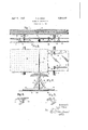
- Figure 1 is a vertical section
- Figure 2 is a bottom plan view
- Figure 3 is an enlarged section
- Figures 4 and 5 are perspective views showing double and single wing fastening stirrups, respectively.
- 6 indicates a side wall, partition, or ceiling of a building, all of which parts I intend to include in the general term wall when used in the specification or claims.
- Carried by the wall 6 are the studs or joists 7 to which the insulating sheet 8 is to be secured.
- the insulating sheet as is set forth in my prior patent above referred to, is provided at regular intervals with hinged spacing strips.
- each of these spacing strips is formed of a piece of wire 9 having formed in it at regular intervals loops 1O determining the width of the strip. These loops are attached by staples 11 to the insulating sheet 8, the loops and staples forming hinges between the strips and the insulating sheet so that the former may be folded against the latter for shipping or storing.
- VVh1le the clips used in open position are provided with two wings 14, as shown in Fi ure 4, those which are placed close to an ad oining wall have one of the wings omitted, as shown in Figure 5.
- the loop 10 is so shaped as to provide a pair of locking shoulders 19 for engagement with the edges of the locking flanges 18, the sides of the loop being flared to form recesses for the reception of the locking flanges which spring into the recesses after they are forced into the loop through its throat 20.
- the rela- 8'5 tive length of the loop and flanges should be such that the apex of the flanges has a bearing against the narrow end of the loop while the edges of the locking flanges bear on the locking shouldersand the body of the 90 panel lies against or close to the spacing strip 9.
- the combi- 40 nation with a lining sheet, of spacing strips each formed of wire having laterally pro- ,Eacting shouldered loops, said loops being inged to the lining sheet, panels having flanges projecting therefrom, spring locking Wflanges carried by said first named flanges and adapted to engage with the shoulders of said loops to positively lock said panels in position, and clips adapted to embrace said strips at any point in their length to hold them in extended position.
Landscapes
- Engineering & Computer Science (AREA)
- Architecture (AREA)
- Civil Engineering (AREA)
- Structural Engineering (AREA)
- Finishing Walls (AREA)
Description
April] 119 11932.
- T. A. WRAY 11,854,438
BUILDING CONSTRUCTION Filed Jan. 8, 1931 o o o o 0 0 a O O O- O O 9 O (7 o o o a o c o 0 o o o O o o 0 o D O O O O O 0 O o o o o o 0 0 0 o o o o o o 0 O o 0 O o O 0 D o n O c c o O 0 o c 0 0 o o o o O O 0' O O O D O O O O 0 O O O O O O o o O o g o o 0 o o o u D o o o o o O 0 .0 o o o o o o 0 o o o o 0 f7 o o o o o a o 57- I 0 o 0 o o o o o o 0 o o o o 0 o o 0 0 o o 0 O 8 0 O O- l8 PILgOS v lnventior v @Q Q/ Att yo Patented Apr. 19," 1932 UNITED STATES THOMAS A. WRAY, OF WEBSTER GROVES, MISSOURI BUILDING CONSTRUCTION Application filed January 8, 1981. Serial No. 507,850.
My invention relates to the construction of side walls, partitions, or ceilings of buildings and particularly to improvements in that type of wall or ceiling construction shown and described in Patent No. 1,780,731,
granted to me November 4, 1930, in which a lining sheet of flax fiber or the like has hinged to it spacing strips adapted to'fold against the lining for convenience in storing and shipping.
The ob ect of the present invention is not only to simplify and improve the construction, but to adapt it for supporting metallic panels as well as expanded metal lathing l5 and the like. 7
In the accompanying drawings, which illustrate one form of building construction made in accordance with my invention, Figure 1 is a vertical section; Figure 2 is a bottom plan view; Figure 3 is an enlarged section; and Figures 4 and 5 are perspective views showing double and single wing fastening stirrups, respectively.
Referring first to Figure 1, 6 indicates a side wall, partition, or ceiling of a building, all of which parts I intend to include in the general term wall when used in the specification or claims. Carried by the wall 6 are the studs or joists 7 to which the insulating sheet 8 is to be secured.
The insulating sheet, as is set forth in my prior patent above referred to, is provided at regular intervals with hinged spacing strips. I
In the present construction each of these spacing strips is formed of a piece of wire 9 having formed in it at regular intervals loops 1O determining the width of the strip. These loops are attached by staples 11 to the insulating sheet 8, the loops and staples forming hinges between the strips and the insulating sheet so that the former may be folded against the latter for shipping or storing. In order to hold the spacing strips at right angles to the insulatin sheet, I employ clips or stirrups 12 stradd ing the spacing strips and fastened in place b nails 13 passing through wings 14 and the insulating sheet 8 into the studding 7. As these clips may be moved along the strips to any desired position, the spacing of the studding does not affect the application of the sheet. VVh1le the clips used in open position are provided with two wings 14, as shown in Fi ure 4, those which are placed close to an ad oining wall have one of the wings omitted, as shown in Figure 5.
If the construction is to be completed by the application of expanded metal or similar lathing neither the shape nor the spacing of the loops 10 is of importance. When, however, the construction is to be finished by the application of metal panels the loops are spaced to conform to the size of the panels. This result may be secured by placing the loops four inches apart as it is the practice to make these panels of dimensions which are multiples of four inches, as for example, sixteen inches square. Heretofore metal panels for covering walls and more particularly ceilings, have consisted of a square or rectangular part or panel proper 16 having its edges bent over at right angles to form flanges 17. In carrying out my invention I provide a pair of flanges 17 located at opposite sides of the panel with reverse or locking flanges 18. These locking flanges project inwardly at an angle to the flanges 17 as most clearly shown in Figure 3. The loop 10 is so shaped as to provide a pair of locking shoulders 19 for engagement with the edges of the locking flanges 18, the sides of the loop being flared to form recesses for the reception of the locking flanges which spring into the recesses after they are forced into the loop through its throat 20. The rela- 8'5 tive length of the loop and flanges should be such that the apex of the flanges has a bearing against the narrow end of the loop while the edges of the locking flanges bear on the locking shouldersand the body of the 90 panel lies against or close to the spacing strip 9. Due to this construction the panels are secured firmly and positively in place simply by forcing them into position without the use of any fastening devices such as tie wires, nails, or screws. In the drawings I have shown the panels 16 as provided with erforations as such perforated panels used in connection with a base of material such as flax fiber, greatly enhance the acoustic properties of the structure to which they are app ied but it will be apparent that my construction is equally applicable for use in connection with imperforate paneling. Felt 5 washers 21 may be used under the heads of the nails 13 to aid in preventing the transmission of sound.
When my construction is used in connection with expanded metal or similar lathing material for the reception of plaster or stucco, it has all the features set forth in my prior patent, above referred to, with the advantage that the spacing trips are lighter and more cheaply manufa tured. Further, owing to 15 the fact that the clips may be applied at any point along the strips, no difficulty is encountered in securing the structure in position when the studding is not uniformly spaced. When used in connection with metallic panel- 20 ing the construction provides an easy means of applying and positive means for holding the panels in position.
Having fully described my invention, what I claim as new and desire to secure by 5 Letters Patent of the United" States is:
' 1. In a building construction, the combination with a lining sheet, of spacing strips .hinged to said sheet to fold against it, said strips being provided with shouldered rem cesses, panels having locking members adapted to engage with the shoulders of said recesses to positively lock said panels in position, and means for holding said strips in extended position.
36 2. In a building construction, the combi- 'nation with a lining sheet, of spacin strips each formed of wire having laterally projectin shouldered loops, said loops being hinge to the lining sheet, panels having lock- 40 ing members adapted to engage with the shoulders of said loops to positively lock said :panels in position, and means for holding said spacing strips in extended position.
3. In a building construction, the combi- 40 nation with a lining sheet, of spacing strips each formed of wire having laterally pro- ,Eacting shouldered loops, said loops being inged to the lining sheet, panels having flanges projecting therefrom, spring locking Wflanges carried by said first named flanges and adapted to engage with the shoulders of said loops to positively lock said panels in position, and clips adapted to embrace said strips at any point in their length to hold them in extended position.
In testimony whereof, I hereunto afiix my signature, this 5th day of January, 1931.
- T. A. WRAY.
Priority Applications (1)
| Application Number | Priority Date | Filing Date | Title |
|---|---|---|---|
| US507350A US1854438A (en) | 1931-01-08 | 1931-01-08 | Building construction |
Applications Claiming Priority (1)
| Application Number | Priority Date | Filing Date | Title |
|---|---|---|---|
| US507350A US1854438A (en) | 1931-01-08 | 1931-01-08 | Building construction |
Publications (1)
| Publication Number | Publication Date |
|---|---|
| US1854438A true US1854438A (en) | 1932-04-19 |
Family
ID=24018300
Family Applications (1)
| Application Number | Title | Priority Date | Filing Date |
|---|---|---|---|
| US507350A Expired - Lifetime US1854438A (en) | 1931-01-08 | 1931-01-08 | Building construction |
Country Status (1)
| Country | Link |
|---|---|
| US (1) | US1854438A (en) |
Cited By (9)
| Publication number | Priority date | Publication date | Assignee | Title |
|---|---|---|---|---|
| DE1130986B (en) * | 1960-03-14 | 1962-06-07 | Karlheinz Arnau | Hollow profile rail for receiving anchor links for a hanging cover or the like. |
| DE1160155B (en) * | 1958-01-17 | 1963-12-27 | Unitone Accustic Tiles Ltd | False ceiling |
| DE1229702B (en) * | 1961-03-09 | 1966-12-01 | Ernst Schneider | Support for ribbed expanded sheet metal |
| US4381631A (en) * | 1981-04-29 | 1983-05-03 | Frommelt Industries, Inc. | Loading dock shelters |
| US5056287A (en) * | 1990-08-30 | 1991-10-15 | Michael Weber | Panel mounting construction and method of use |
| US6138431A (en) * | 1998-10-13 | 2000-10-31 | Da Encarnacao; Fernando Antonio Franco | Virtual block for attachment to a prefabricated ceiling slab |
| US20060075710A1 (en) * | 2004-09-29 | 2006-04-13 | Ig Creative Solutions | Housing construction system |
| US20090277117A1 (en) * | 2008-05-06 | 2009-11-12 | Worthington Armstrong Venture | Suspended ceiling cloud with flexible panel |
| US20110072744A1 (en) * | 2004-09-29 | 2011-03-31 | Ig Creative Solutions, Inc. | Housing construction system |
-
1931
- 1931-01-08 US US507350A patent/US1854438A/en not_active Expired - Lifetime
Cited By (15)
| Publication number | Priority date | Publication date | Assignee | Title |
|---|---|---|---|---|
| DE1160155B (en) * | 1958-01-17 | 1963-12-27 | Unitone Accustic Tiles Ltd | False ceiling |
| DE1130986B (en) * | 1960-03-14 | 1962-06-07 | Karlheinz Arnau | Hollow profile rail for receiving anchor links for a hanging cover or the like. |
| DE1229702B (en) * | 1961-03-09 | 1966-12-01 | Ernst Schneider | Support for ribbed expanded sheet metal |
| US4381631A (en) * | 1981-04-29 | 1983-05-03 | Frommelt Industries, Inc. | Loading dock shelters |
| US5056287A (en) * | 1990-08-30 | 1991-10-15 | Michael Weber | Panel mounting construction and method of use |
| US6138431A (en) * | 1998-10-13 | 2000-10-31 | Da Encarnacao; Fernando Antonio Franco | Virtual block for attachment to a prefabricated ceiling slab |
| US20060075710A1 (en) * | 2004-09-29 | 2006-04-13 | Ig Creative Solutions | Housing construction system |
| US7810294B2 (en) * | 2004-09-29 | 2010-10-12 | Ig Creative Solutions, Inc. | Housing construction system |
| US20110072744A1 (en) * | 2004-09-29 | 2011-03-31 | Ig Creative Solutions, Inc. | Housing construction system |
| US8820018B2 (en) | 2004-09-29 | 2014-09-02 | Ig Creative Solutions, Inc. | Housing construction system |
| US9410318B2 (en) | 2004-09-29 | 2016-08-09 | Ig Creative Solutions, Inc. | Housing construction system |
| US10161131B2 (en) | 2004-09-29 | 2018-12-25 | IG Creative Solutions Inc. | Housing construction system |
| US10900227B2 (en) | 2004-09-29 | 2021-01-26 | Ig Creative Solutions, Inc. | Housing construction system |
| US20090277117A1 (en) * | 2008-05-06 | 2009-11-12 | Worthington Armstrong Venture | Suspended ceiling cloud with flexible panel |
| US8096089B2 (en) * | 2008-05-06 | 2012-01-17 | Worthington Armstrong Venture | Suspended ceiling cloud with flexible panel |
Similar Documents
| Publication | Publication Date | Title |
|---|---|---|
| US2059483A (en) | Replaceable unit ceiling construction | |
| US2000243A (en) | Wall construction | |
| US2796158A (en) | Wall assembly | |
| US2020062A (en) | Structural building device | |
| US1782147A (en) | Metal arch member for openings | |
| US1959135A (en) | Wall construction | |
| US2064704A (en) | Arch construction | |
| US1854438A (en) | Building construction | |
| US1935536A (en) | Building construction | |
| US2013763A (en) | Building construction | |
| US2368620A (en) | Wall construction | |
| US2041773A (en) | Resilient building wall clip construction | |
| US1775234A (en) | Concrete building construction | |
| US1940933A (en) | Wall and ceiling construction | |
| US2013762A (en) | Building construction | |
| US2186511A (en) | Wallboard | |
| US2352002A (en) | Panel fastening element | |
| US1852049A (en) | Building construction | |
| US2745277A (en) | Ceiling runners and partition structure | |
| US2026117A (en) | Resilient building construction | |
| US2296609A (en) | Building construction | |
| US1951346A (en) | Partition construction | |
| US1691179A (en) | Material-fastening device | |
| US1820123A (en) | Partition | |
| US1161764A (en) | Sheet-metal structure. |