US1852530A - Hat pressing machine - Google Patents
Hat pressing machine Download PDFInfo
- Publication number
- US1852530A US1852530A US373603A US37360329A US1852530A US 1852530 A US1852530 A US 1852530A US 373603 A US373603 A US 373603A US 37360329 A US37360329 A US 37360329A US 1852530 A US1852530 A US 1852530A
- Authority
- US
- United States
- Prior art keywords
- hat
- crown
- pressing machine
- opening
- support
- Prior art date
- Legal status (The legal status is an assumption and is not a legal conclusion. Google has not performed a legal analysis and makes no representation as to the accuracy of the status listed.)
- Expired - Lifetime
Links
- 230000000284 resting effect Effects 0.000 description 10
- 238000010025 steaming Methods 0.000 description 6
- 230000014509 gene expression Effects 0.000 description 2
- 238000010438 heat treatment Methods 0.000 description 2
- 230000000630 rising effect Effects 0.000 description 2
- VJYFKVYYMZPMAB-UHFFFAOYSA-N ethoprophos Chemical compound CCCSP(=O)(OCC)SCCC VJYFKVYYMZPMAB-UHFFFAOYSA-N 0.000 description 1
- 230000004048 modification Effects 0.000 description 1
- 238000012986 modification Methods 0.000 description 1
Images
Classifications
-
- A—HUMAN NECESSITIES
- A42—HEADWEAR
- A42C—MANUFACTURING OR TRIMMING HEAD COVERINGS, e.g. HATS
- A42C1/00—Manufacturing hats
- A42C1/04—Blocking; Pressing; Steaming; Stretching
Definitions
- This invention relates to certain new and useful improvements in hat forming or hat pressing machines, and it hasfor its objects, among others, to provide an improved device of this general character, which, while simple in its nature, will be found most effective in its work, requiring practically no attention on the part of the operator, composed of few parts and those readily assembled and removed, readily replaceable whenever occasion may require, and most eliicient in the results.
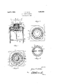
- Figure 1 is a substantially central vertical section through a hat forming or pressing machine constructed in accordance with my present invention.
- Figure 2 is a top plan view with the upper members thereof removed.
- Figure 3 is a top plan view with the steam retainer removed and the under portions shown by dotted lines.
- Figure 4 is a top plan of the steam retainer.
- FIG. 1 eferring to the drawings 1 designates a suitable support, in this lilstance, but not necessarily so, comprising legs 2 of angle form, see Figures 1 and 3, and an angle form top portion 3, which serves to support the operative parts of the device. As shown, the legs are braced near their lower ends by a suitable brace 4.
- a heat shield 5 Supported in any suitable manner beneath the table top is a heat shield 5, in the present instance being provided at its upper end with a surrounding flange 6 for this purpose.
- This shield is provided with suitable means, as a gas-lighting door, that is means permitting access to the gas jet soon to be described.
- suitable means as a gas-lighting door, that is means permitting access to the gas jet soon to be described.
- the member 8 is provided with an upstanding surrounding flange 12 for a purpose soon to be described. It is further formed with the central lip-standing portion 13 rising from the angular flange portion 14, see Figure 1, which rises from the inner wall of an annular channel 15. This channel is such as to receive different sizes of forming dies now to be described.
- FIG. 1 One of such forming dies is shown in Figure 1 at 16, which is shown as provided with a depending annular flange 17 which is removably engaged in the said annular channel 15.
- This die 16 is designed to be engaged by the hat, shown at 18, it being noted from Figure 1 that there is a space 19 between the upstanding portions of the interfitting members 13 and 16 so that the two members do not come in contact with each other except at the bases thereof.
- the upper face of the member is curved as seen at 20 in order to conform to the curved shape of the brim of the hat, as will be readily understood upon reference to F igure 1.
- FIG. 21 is a heat retainer having an annular flange 22 to be received within the flange 12 of the member 8 as seen clearly in Figure 1 and thus the said heat retainer is held in position but readily removable.
- At the base of the crown of the member 21 it is provided with a curved flange portion 23, see Figure 1, conforming to the curvature 20 of thememher 8, seen in position on top of the brim of the hat.
- the member 21 is provided with a suitable means whereby it may be handled; in this in stance this is shown as in theform of a rod 25.
- 26 is a gas line, provided with suitable valve 27, and from which line extends upward a portion 27, the upper end of which is provided with a gas jet 28, while also from said upwardly extending portion there is a horizontal branch 29 at each end of which is a lateral branch 30 and 31, which branches are arc-shaped as seen in Figure .1. 7
- I may use not only gas,.but steam or any other power available.
- a hat steaming and pressing machine embodying a heat shield, heating means within the same, spaced-apart members independent of the heating means between which the hat is confined during treatment,- and means for detachably supportingall of the elements except the said shield in position above the latter.
- a hat steaming and pressing machine comprising a support formed with an opening, a heat shield secured to said support beneath the opening, a cover having a base resting upon said support in covering relation to the opening, and a crown extending upwardly, a heater in the space between the shield and cover, a crown shaped forming die resting upon said cover about said crown and spaced from the crown whereby a hat to be treated may be fitted upon the forming die with its brim resting upon the base of said cover, and a heat retainer disposed about the forming die is spaced relation thereto to form a steam chamber and having a base portion to rest upon the brim of a hat.
- a hat steaming. and pressing machine comprising a support formed with an opening, a heat shield secured to said support beneath the opening, a cover having a base resting upon said support in covering relation to the opening, and a crown extending upwardly, a heater in the space between the shield and cover having a portion-extending upwardly into the crown, a forming die fitting about said crown in spaced relation thereto,- and a heat retainer fittingabout the forming die and together therewith forming a steam chamber.
- a hat steaming and pressing machine comprising a support formed with an opening, a heat shield secured to said support be neath the opening, a heater surrounded by said shield, a cover for said opening having a base resting upon said support and aerown extending upwardly, a seat being formed about the lower portion of said crown, a crown shaped forming die disposed about said crown and resting in. said seat, and a heat retainer disposed about said rormingdie in spaced relation thereto and restingupon said base.
- a hat steaming and pressing machine comprising a support formed with an opening, a heat shield secured to said support beneath the opening, a heater surroundedby said shield, a cover for said opening having a base resting upon said support and a crown extending upwardly, a seat being formed about the lower portion of said crown, a crown shaped forming die disposed about said crown and having a flared lower portion resting in said seat with its upper face flush with the upper face of said base, and a crown portion heat retainer disposed about the forming die in spaced relation thereto and a brim overlying the base of said cover.
- a hat steaming and pressing machine comprising a support formed with an opening, a heat shield secured to said support beneath the opening, a heater surrounded by said shield, a cover for said opening. having abase resting upon said support and a crown extending upwardly, a forming die resting upon said cover about the crown thereof, an annular flange rising from said base, and a heat retainer surrounding the forming die and held in spacedrelation thereto by said flange.
Landscapes
- Engineering & Computer Science (AREA)
- Manufacturing & Machinery (AREA)
- Treatment Of Fiber Materials (AREA)
Description
April 5, 1932. c 0115 1,852,530
HAT PRESSING MACHINE Filed June 25, 1929 Patented Apr. 5, 1932 UNITED STATES JAMES G. KOTIS, OF MOBILE, ALABAMA HAT PBESSING MACHINE Application filed June 25,
This invention relates to certain new and useful improvements in hat forming or hat pressing machines, and it hasfor its objects, among others, to provide an improved device of this general character, which, while simple in its nature, will be found most effective in its work, requiring practically no attention on the part of the operator, composed of few parts and those readily assembled and removed, readily replaceable whenever occasion may require, and most eliicient in the results.
Other objects and advantages of the invention will hereinafter appear and the novel features thereof will be specifically dc fined by .15 the appended claims.
The invention, in its preferred form, is clearly illustrated in the accompanying drawings, which, with the numerals of reference marked thereon, form a part of this specification, and in which Figure 1 is a substantially central vertical section through a hat forming or pressing machine constructed in accordance with my present invention.
Figure 2 is a top plan view with the upper members thereof removed.
Figure 3 is a top plan view with the steam retainer removed and the under portions shown by dotted lines.
Figure 4 is a top plan of the steam retainer.
Like numerals of reference indicate like parts throughout the several views in which the appear.
1 eferring to the drawings 1 designates a suitable support, in this lilstance, but not necessarily so, comprising legs 2 of angle form, see Figures 1 and 3, and an angle form top portion 3, which serves to support the operative parts of the device. As shown, the legs are braced near their lower ends by a suitable brace 4.
Supported in any suitable manner beneath the table top is a heat shield 5, in the present instance being provided at its upper end with a surrounding flange 6 for this purpose. This shield is provided with suitable means, as a gas-lighting door, that is means permitting access to the gas jet soon to be described. Such provision is seen at 7 in Figure 1.
Supported on the top portion 3 is the heat 1929. Serial 1T0. 373,603.
and forming die 8, which is removably supported in position upon the top portion 3, in the present instance being shown as provided in its flange portion 9 with openings 10 to receive the pins 11 projecting upward from the horizontal portion of the table top 3, as seen best in Figure 1. This permits of the ready removal of the member 8 when desired.
The member 8 is provided with an upstanding surrounding flange 12 for a purpose soon to be described. It is further formed with the central lip-standing portion 13 rising from the angular flange portion 14, see Figure 1, which rises from the inner wall of an annular channel 15. This channel is such as to receive different sizes of forming dies now to be described.
One of such forming dies is shown in Figure 1 at 16, which is shown as provided with a depending annular flange 17 which is removably engaged in the said annular channel 15. This die 16 is designed to be engaged by the hat, shown at 18, it being noted from Figure 1 that there is a space 19 between the upstanding portions of the interfitting members 13 and 16 so that the two members do not come in contact with each other except at the bases thereof.
The upper face of the member is curved as seen at 20 in order to conform to the curved shape of the brim of the hat, as will be readily understood upon reference to F igure 1.
21 is a heat retainer having an annular flange 22 to be received within the flange 12 of the member 8 as seen clearly in Figure 1 and thus the said heat retainer is held in position but readily removable. At the base of the crown of the member 21 it is provided with a curved flange portion 23, see Figure 1, conforming to the curvature 20 of thememher 8, seen in position on top of the brim of the hat.
The upstanding portions of the members 16 and 21 are soproportioned as to leave therebetween a space 24 as seen in Figure 1.
The member 21 is provided with a suitable means whereby it may be handled; in this in stance this is shown as in theform of a rod 25.
for the steam therein.
26 is a gas line, provided with suitable valve 27, and from which line extends upward a portion 27, the upper end of which is provided with a gas jet 28, while also from said upwardly extending portion there is a horizontal branch 29 at each end of which is a lateral branch 30 and 31, which branches are arc-shaped as seen in Figure .1. 7
The operation is apparent; with the parts in the position in which they are shown in Figure 1, with the hat in place and the gas turned on and lighted, the hat having been dampened, the heat converts the moisture into steam and the hat is simultaneously shaped and pressed. It takes but. a short period of time to get the desired result, when the hat can be quickly removed and another place in position. The steam retainer and the forming die and the heat and forming die serve conjointly to produce most satisfactory results with the consumption of minimum time.
The terms and expressions which I have employed are used as terms of description and not of limitation, and I have no intention, in the use of such terms and expressions, of excluding any equivalents of the features shown and described, or portions thereof, but recognize that various modifications are possible within the scope of the invention claimed herein.
For instance, I may use not only gas,.but steam or any other power available.
What is claimed as new is 1. A hat steaming and pressing machine embodying a heat shield, heating means within the same, spaced-apart members independent of the heating means between which the hat is confined during treatment,- and means for detachably supportingall of the elements except the said shield in position above the latter.
2. A hat steaming and pressing machine comprising a support formed with an opening, a heat shield secured to said support beneath the opening, a cover having a base resting upon said support in covering relation to the opening, and a crown extending upwardly, a heater in the space between the shield and cover, a crown shaped forming die resting upon said cover about said crown and spaced from the crown whereby a hat to be treated may be fitted upon the forming die with its brim resting upon the base of said cover, and a heat retainer disposed about the forming die is spaced relation thereto to form a steam chamber and having a base portion to rest upon the brim of a hat.
3. A hat steaming. and pressing machine comprising a support formed with an opening, a heat shield secured to said support beneath the opening, a cover having a base resting upon said support in covering relation to the opening, and a crown extending upwardly, a heater in the space between the shield and cover having a portion-extending upwardly into the crown, a forming die fitting about said crown in spaced relation thereto,- and a heat retainer fittingabout the forming die and together therewith forming a steam chamber.
4:. A hat steaming and pressing machine comprising a support formed with an opening, a heat shield secured to said support be neath the opening, a heater surrounded by said shield, a cover for said opening having a base resting upon said support and aerown extending upwardly, a seat being formed about the lower portion of said crown, a crown shaped forming die disposed about said crown and resting in. said seat, and a heat retainer disposed about said rormingdie in spaced relation thereto and restingupon said base.
5. A hat steaming and pressing machine comprising a support formed with an opening, a heat shield secured to said support beneath the opening, a heater surroundedby said shield, a cover for said opening having a base resting upon said support and a crown extending upwardly, a seat being formed about the lower portion of said crown, a crown shaped forming die disposed about said crown and having a flared lower portion resting in said seat with its upper face flush with the upper face of said base, and a crown portion heat retainer disposed about the forming die in spaced relation thereto and a brim overlying the base of said cover.
6. A hat steaming and pressing machine comprising a support formed with an opening, a heat shield secured to said support beneath the opening, a heater surrounded by said shield, a cover for said opening. having abase resting upon said support and a crown extending upwardly, a forming die resting upon said cover about the crown thereof, an annular flange rising from said base, and a heat retainer surrounding the forming die and held in spacedrelation thereto by said flange.
In testimony whereof I aflix my signature.
JAMES C. KOTIS.
Priority Applications (1)
| Application Number | Priority Date | Filing Date | Title |
|---|---|---|---|
| US373603A US1852530A (en) | 1929-06-25 | 1929-06-25 | Hat pressing machine |
Applications Claiming Priority (1)
| Application Number | Priority Date | Filing Date | Title |
|---|---|---|---|
| US373603A US1852530A (en) | 1929-06-25 | 1929-06-25 | Hat pressing machine |
Publications (1)
| Publication Number | Publication Date |
|---|---|
| US1852530A true US1852530A (en) | 1932-04-05 |
Family
ID=23473096
Family Applications (1)
| Application Number | Title | Priority Date | Filing Date |
|---|---|---|---|
| US373603A Expired - Lifetime US1852530A (en) | 1929-06-25 | 1929-06-25 | Hat pressing machine |
Country Status (1)
| Country | Link |
|---|---|
| US (1) | US1852530A (en) |
-
1929
- 1929-06-25 US US373603A patent/US1852530A/en not_active Expired - Lifetime
Similar Documents
| Publication | Publication Date | Title |
|---|---|---|
| US1852530A (en) | Hat pressing machine | |
| US2429047A (en) | Garment forming machine | |
| US1888375A (en) | Hat steaming and blocking attachment | |
| US1685829A (en) | Cooking apparatus | |
| US1659415A (en) | Means for heating grease for cookers | |
| US910345A (en) | Gas heater and cooker. | |
| US2817466A (en) | Hat steaming and blocking machine | |
| US1881581A (en) | Garment pressing machine | |
| US1768768A (en) | Machine for baking hat stays | |
| US2534831A (en) | Circular steaming unit for umbrellas | |
| US2454571A (en) | Culinary oven with heat diverting means | |
| US1977366A (en) | Coffee maker | |
| US1711140A (en) | Oil burner | |
| US1386230A (en) | Hat-cleaning machine | |
| US1711094A (en) | Drier and steamer for tubular fabrics | |
| US2149605A (en) | Steaming device | |
| US1715282A (en) | Washboiler | |
| US1740008A (en) | District osi colttmbia | |
| US1303190A (en) | Hat-eenovating machote | |
| US533588A (en) | Face-steamer | |
| US1716735A (en) | Steaming device for hats | |
| US2626793A (en) | Wrinkle remover for shoes | |
| US1668123A (en) | Puff iron | |
| US427069A (en) | Steam-box for dampening cloth | |
| US1559636A (en) | Hat-steaming device |