US1852490A - Heat exchanger - Google Patents
Heat exchanger Download PDFInfo
- Publication number
- US1852490A US1852490A US516488A US51648831A US1852490A US 1852490 A US1852490 A US 1852490A US 516488 A US516488 A US 516488A US 51648831 A US51648831 A US 51648831A US 1852490 A US1852490 A US 1852490A
- Authority
- US
- United States
- Prior art keywords
- heat
- core
- fluid
- conduit
- conduits
- Prior art date
- Legal status (The legal status is an assumption and is not a legal conclusion. Google has not performed a legal analysis and makes no representation as to the accuracy of the status listed.)
- Expired - Lifetime
Links
Images

Classifications
-
- F—MECHANICAL ENGINEERING; LIGHTING; HEATING; WEAPONS; BLASTING
- F28—HEAT EXCHANGE IN GENERAL
- F28D—HEAT-EXCHANGE APPARATUS, NOT PROVIDED FOR IN ANOTHER SUBCLASS, IN WHICH THE HEAT-EXCHANGE MEDIA DO NOT COME INTO DIRECT CONTACT
- F28D7/00—Heat-exchange apparatus having stationary tubular conduit assemblies for both heat-exchange media, the media being in contact with different sides of a conduit wall
- F28D7/02—Heat-exchange apparatus having stationary tubular conduit assemblies for both heat-exchange media, the media being in contact with different sides of a conduit wall the conduits being helically coiled
- F28D7/024—Heat-exchange apparatus having stationary tubular conduit assemblies for both heat-exchange media, the media being in contact with different sides of a conduit wall the conduits being helically coiled the conduits of only one medium being helically coiled tubes, the coils having a cylindrical configuration
-
- F—MECHANICAL ENGINEERING; LIGHTING; HEATING; WEAPONS; BLASTING
- F28—HEAT EXCHANGE IN GENERAL
- F28D—HEAT-EXCHANGE APPARATUS, NOT PROVIDED FOR IN ANOTHER SUBCLASS, IN WHICH THE HEAT-EXCHANGE MEDIA DO NOT COME INTO DIRECT CONTACT
- F28D7/00—Heat-exchange apparatus having stationary tubular conduit assemblies for both heat-exchange media, the media being in contact with different sides of a conduit wall
- F28D7/10—Heat-exchange apparatus having stationary tubular conduit assemblies for both heat-exchange media, the media being in contact with different sides of a conduit wall the conduits being arranged one within the other, e.g. concentrically
- F28D7/14—Heat-exchange apparatus having stationary tubular conduit assemblies for both heat-exchange media, the media being in contact with different sides of a conduit wall the conduits being arranged one within the other, e.g. concentrically both tubes being bent
-
- Y—GENERAL TAGGING OF NEW TECHNOLOGICAL DEVELOPMENTS; GENERAL TAGGING OF CROSS-SECTIONAL TECHNOLOGIES SPANNING OVER SEVERAL SECTIONS OF THE IPC; TECHNICAL SUBJECTS COVERED BY FORMER USPC CROSS-REFERENCE ART COLLECTIONS [XRACs] AND DIGESTS
- Y10—TECHNICAL SUBJECTS COVERED BY FORMER USPC
- Y10S—TECHNICAL SUBJECTS COVERED BY FORMER USPC CROSS-REFERENCE ART COLLECTIONS [XRACs] AND DIGESTS
- Y10S165/00—Heat exchange
- Y10S165/355—Heat exchange having separate flow passage for two distinct fluids
- Y10S165/40—Shell enclosed conduit assembly
- Y10S165/401—Shell enclosed conduit assembly including tube support or shell-side flow director
- Y10S165/405—Extending in a longitudinal direction
- Y10S165/414—Extending in a longitudinal direction for supporting coil tubes
Definitions
- This invention relates to heat exchangers
- the primary object of the present invention is to provide improvements in heat exchangers utilizing heat exchange elements and units of the general type disclosed in my co-pending application for U. S. Letters 4Pat- 1o ent Serial Number 516,487, filed February 17 1931, whereby an extremely thorough exchange of heat ,between the fluids is eiected as required in certain specific uses of heat exchangers.
- a heat exchan e unit including a iiuid conduit in the form o a flattened spirally twisted tube.
- Means is provided to pass one fluid through these coils and to pass-the other fluid-about such coils so that the latter Huid is maintained in a highly turbulent state for eilicient heat interchanging action. Due to the coiled form of the flattened spirally twisted conduits, the iiud ilowing therethrough will be of relatively large volume and will travel in a comparatively long path as comparedto the actual length of the heat exchanger, thus insuring a device of maximum capacity and eiliciency. 0 e
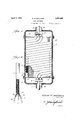
- Figure 1 is a vertical section of a heat exf changer constructedin accordance with the present invention.
- Figure 2 is a transverse section on line 2--2v of Figure 1.
- Y Figure 3 is a transverse section online 3f--3 of Flgure 1.
- Figure 4 is an elevational view of the ilattened spirally twisted tube used to form the respective coils ofthe heat exchanger" 30 -shown in Figurel. f
- Figure 6 is a fragmentary elevation, partlyA a5 broken and in section, of one of the heatexchange elements utilized vto form the respec'- tive coils of the heat exchanger shown inA Figure 5e -latteris a straight tubular conduit 11 which 80 connects at its opposite end respectively with outlet and supply chambers 12 and. 13 encasing the headers 7 and 8 and respectively provided with ilu'id outlet and inlet pipes 14 and 15 surrounding the 'inlet and outlet pipes 9 85 v and 10.
- Each of the coiled. conduits 6 is formed from a length of flattened spirally twisted tubing as shown at 5b in Figure4 and clearly described in connection with lFi res 1v to iV 05 inclusive of my co-pending appllcation mentioned above. As explained 1n said a plication, this provides each conduit 6 with wide opposed walls which are subjected throughv out their width to the heating or cooling ac- Such other fluid, as will be readily seen, flows about th conduits 6 between the latter and the conduit 11, passing in helical paths about the core 5 parallel with the coils of these conduits 6 and also following the twists of the latter.
- the fluid will pass to some extent -in a'straight path directly acrossI the c oils of the conduits 6, and in this way the fluid in the outer conduit 11 is brought to and maintained in a very highly turbulent state so as to insure most efficient and uniform .heat interchanging action.
- the efliciency of this action is enhanced by permitting some of the fluid to flow through the core 5 in addi.
- the heat exchanger is preferably of the countercurrent type in which one fluid passes through the conduits 6 in one direction and through the conduit 11 in the opposite direction.
- a'modified form of heat exchanger including a core 5 of relatively large diameter about which is coiled or helically wound from end to end in side by side or parallel relation a plurality' of heat exchange units, each of which includes a fluid conduit 6 in the form of a flattened spirally twisted tube.
- 'Ihe conduits 6 of these heat exchange units have their adjacent ends connected at the opposite ends of the core 5 respectively with headers 7 and 8 having fluid supply and outlet pipes 9'- and 10 respectively.
- Each heat exchange unit also includes a tubular aconduit 11 snugly encasing the. conduit 6 of that unit and coiled about the core 5.
- the adjacent ends of the conduits 11 of the several heat exchange units open at oppo-- site ends of the core 5 respectively into fluid l outlet and inlet pipes 14 and 15 'ing theinlet and -outlet'pipes 9'"and 10.
- outlet and inlet chambers 12 and 13 having surroundsuitable casing 16 surrounds the core 5 and the coiled heat exchange units 'wound about the same, and this casing may be suitably heat-insulated as indicated at 17. Alsofthe chambers 12 and 13 are preferably heat insulated as indicated at may preferably be filled zwith suitable heat insulating material 19 so as to minimize absorption of heat through the core- 5. While 1n some uses,
- the heat'exchange units may' only of the inner conduits '6' and outer conduits 11', there arev some uses in which interchange is necessary;
- I preferably arrange rods 20 at opposite sides of the flattened spirally twisted r conduit 6 of each heat exchange unit, such rods being loosely coiled about the twisted' conduits 6 and then twisted tightly with the Ication ,referred to above, depending upon vwhether or not the rods 2O are solid or tubular.
- one fluid enters the conduits 6 of the several helically wound heat exchange units from header 7 and passes therethrough to the header 8.
- the other fluid through the conduits 11 of the heat exc ange units from chamber 13 to chamber 12', being in this way caused to flow in an exceedingly long path in heat interchanging relation with the other fluid passing through the conduits 6.
- the two fluids are brought to a highly turbulent state and in most thorough heat interchanging relation.
- a core a plurality of fluid conduits/helically wound about said core in side by side or parallel relation, each of saidconduits bein in the form of a flat. tened spirally twisted tube, means to pass a fluid through said conduits, and means to conduct another fluid ⁇ in heat interchanging relation to said conduits.
- each of sa'idconduits being Ain theform of a flattened spirally twisted tube,.means to passa. fluid through said .eonduits,. and means to conduct another fluid in heat interchanging relation to said conduits, in a reverse direction to the direction of ow of the first fluid through said conduits.
- a core In a heat exchanger, a core, a attened spil-ally twisted conduitl helically wound and means to conduct a fluid iin heat interchanging relation with said con- 4.
- a heat inter'changer having a uid conduit linthe form of ahelically 4wound flattened spirally twisted tube.
- a core In a heat exchanger, a core, a fluid oontluit in the form of a attened spiral-ly twistetl tube helically Wound about said core, and a :further Huid conduit snugly encasng the tirst-named conduit.
- a core In a beat exchanger, a core, a fluid contluit in the form of a flattened spirally twisted tube helically Wound about said core, and .a further fluid conduit snugly encasing the first-named conduit, said core being of hollow open-ended form, and means to pass a fluid through the core and the second-named conduit in heat interchanging relation with a fluid passing through the iirst-named conduit.
- a core in the form of a filgattened spirally twisted tube helically Wound about said core, and a further fluid conduit snugly encasing the hrst-named conduit, said core being of hollow open-ended form, means to pass a fluid through the core and the second named conduit in heat interchanging relation with a fluid passing through they frstna1ned conduit, and means Within the Huid to he brought a turbulent state when core.
Description
E. G. SULLIVAN HEAT EXCHANGER Filed Feb. 17, 1951 2 Sheets-Sheet Y. .mm of w w AMI A, G. d w w W April 5, 1932.
E. G. SULLIVAN HEAT EXCHANGEH FiledvFeb. 17, 1931 2 Sheets-Sheet IN! "EN TOR.
.A1 TTORNEY.
April 5, 1932.
v\\\ lllllllllllllllllll l Patented Apr. 5, 19.32
n UNITED STATES PATENT OFI-Ice EDWARD G.`SULLIVAN, Oil' AIABILLO, ASBIGNOB T0 JOSEPH S. BELT, 0l'
MARMO, TEXAS nur nxcnuenn Application nea rebnary 1"?, mi. serial 1n. 516,408.
This invention relates to heat exchangers,
or to an apparatus for use intransferring heat from one iiuid to another fluid, throng an intervening heat conducting wall. l The primary object of the present invention is to provide improvements in heat exchangers utilizing heat exchange elements and units of the general type disclosed in my co-pending application for U. S. Letters 4Pat- 1o ent Serial Number 516,487, filed February 17 1931, whereby an extremely thorough exchange of heat ,between the fluids is eiected as required in certain specific uses of heat exchangers. In my -co-pending application .mentioned above, there is shown and described a heat exchan e unit including a iiuid conduit in the form o a flattened spirally twisted tube. As shown in said application,'eilicient forms of l0 heat exchangers for many uses may be readily constructed employing a heat exchange unit or units, each of which includes a single iiattene'd spirally twisted conduit of straight form. However, in many uses a higher de-` M gree of eiciency is required involving a reater or more complete exchange of heat etween the two fluids, and the present invention aims to'eiect this result 'by constructing aheat exchanger involving a plurality of the flattened spirally twistedconduits disposed in side by side 'or parallel relation and coiled `about a suitable core Within a casing. Means is provided to pass one fluid through these coils and to pass-the other fluid-about such coils so that the latter Huid is maintained in a highly turbulent state for eilicient heat interchanging action. Due to the coiled form of the flattened spirally twisted conduits, the iiud ilowing therethrough will be of relatively large volume and will travel in a comparatively long path as comparedto the actual length of the heat exchanger, thus insuring a device of maximum capacity and eiliciency. 0 e
The nature of the present invention as well as the objects and advantages thereof will be A more clearly apparent from the following descriptiontaken in connection with the accompanying drawings, in which:
Figure 1 is a vertical section of a heat exf changer constructedin accordance with the present invention.
Figure 2 is a transverse section on line 2--2v of Figure 1.
. Y Figure 3 is a transverse section online 3f--3 of Flgure 1.
Figure 4 is an elevational view of the ilattened spirally twisted tube used to form the respective coils ofthe heat exchanger" 30 -shown in Figurel. f
Figure 51S a viw'siminr to Figure 1 of a.
`modiiied form of heat exchanger embodying p the present invention; and
Figure 6 is a fragmentary elevation, partlyA a5 broken and in section, of one of the heatexchange elements utilized vto form the respec'- tive coils of the heat exchanger shown inA Figure 5e -latteris a straight tubular conduit 11 which 80 connects at its opposite end respectively with outlet and supply chambers 12 and. 13 encasing the headers 7 and 8 and respectively provided with ilu'id outlet and inlet pipes 14 and 15 surrounding the 'inlet and outlet pipes 9 85 v and 10. A casing 16'surrounds the conduit 11, anda packing 17 of heat insulating material is placedbetween the conduit 11 and casing 16. The outlet and inlet chambers. 12 and 13. may be suitably heat-insulated as indi-Y 9c cated at 1823 Each of the coiled. conduits 6 is formed from a length of flattened spirally twisted tubing as shown at 5b in Figure4 and clearly described in connection with lFi res 1v to iV 05 inclusive of my co-pending appllcation mentioned above. As explained 1n said a plication, this provides each conduit 6 with wide opposed walls which are subjected throughv out their width to the heating or cooling ac- Such other fluid, as will be readily seen, flows about th conduits 6 between the latter and the conduit 11, passing in helical paths about the core 5 parallel with the coils of these conduits 6 and also following the twists of the latter. In addition; the fluid will pass to some extent -in a'straight path directly acrossI the c oils of the conduits 6, and in this way the fluid in the outer conduit 11 is brought to and maintained in a very highly turbulent state so as to insure most efficient and uniform .heat interchanging action. The efliciency of this action is enhanced by permitting some of the fluid to flow through the core 5 in addi.
tion to passing about the conduits 6 within the conduit 11. In order to maintain the fluid in a turbulent state as it passes through the inner conduit or core 5. the latter is preferably filled with ducting powder or material as at 19, such material being maintained within the core 5 by means of foraminous closures or gauze disks 2O secured in the opposite open ends of the core 5. VIt will be seen that the heat exchanger is preferably of the countercurrent type in which one fluid passes through the conduits 6 in one direction and through the conduit 11 in the opposite direction.
Referring to Figures 5 and 6, a'modified form of heat exchanger is shown including a core 5 of relatively large diameter about which is coiled or helically wound from end to end in side by side or parallel relation a plurality' of heat exchange units, each of which includes a fluid conduit 6 in the form of a flattened spirally twisted tube. 'Ihe conduits 6 of these heat exchange units have their adjacent ends connected at the opposite ends of the core 5 respectively with headers 7 and 8 having fluid supply and outlet pipes 9'- and 10 respectively.
Each heat exchange unit also includes a tubular aconduit 11 snugly encasing the. conduit 6 of that unit and coiled about the core 5. The adjacent ends of the conduits 11 of the several heat exchange units open at oppo-- site ends of the core 5 respectively into fluid l outlet and inlet pipes 14 and 15 'ing theinlet and -outlet'pipes 9'"and 10.
outlet and inlet chambers 12 and 13 having surroundsuitable casing 16 surrounds the core 5 and the coiled heat exchange units 'wound about the same, and this casing may be suitably heat-insulated as indicated at 17. Alsofthe chambers 12 and 13 are preferably heat insulated as indicated at may preferably be filled zwith suitable heat insulating material 19 so as to minimize absorption of heat through the core- 5. While 1n some uses,
more efficient heat a finely divided heat con-.
18', while the core 5 about said core,
the heat'exchange units may' only of the inner conduits '6' and outer conduits 11', there arev some uses in which interchange is necessary;
In that event, I preferably arrange rods 20 at opposite sides of the flattened spirally twisted r conduit 6 of each heat exchange unit, such rods being loosely coiled about the twisted' conduits 6 and then twisted tightly with the Ication ,referred to above, depending upon vwhether or not the rods 2O are solid or tubular.
They have been illustrated as solid simply for example.
In operation of the heat exchanger shown in Figure 5, one fluid enters the conduits 6 of the several helically wound heat exchange units from header 7 and passes therethrough to the header 8. The other fluid through the conduits 11 of the heat exc ange units from chamber 13 to chamber 12', being in this way caused to flow in an exceedingly long path in heat interchanging relation with the other fluid passing through the conduits 6. In all cases, the two fluids are brought to a highly turbulent state and in most thorough heat interchanging relation.
From the foregoing description, it is believed that the construction and operation, as well as the advantages of the present invention will be'readily understood and appreciated by those skilled in the art. Minor changes are contemplated within'the spirit and scope of the invention as claimed. What I claim as new is: f l
1. In a heat exchanger, a core a plurality of fluid conduits/helically wound about said core in side by side or parallel relation, each of saidconduits bein in the form of a flat. tened spirally twisted tube, means to pass a fluid through said conduits, and means to conduct another fluid `in heat interchanging relation to said conduits.
2. In a' heat exchanger, a core, a lurality of fluid' conduits helically wound agout' said core in side by side or parallel relation, each of sa'idconduitsbeing Ain theform of a flattened spirally twisted tube,.means to passa. fluid through said .eonduits,. and means to conduct another fluid in heat interchanging relation to said conduits, in a reverse direction to the direction of ow of the first fluid through said conduits. A
3. In a heat exchanger, a core, a attened spil-ally twisted conduitl helically wound and means to conduct a fluid iin heat interchanging relation with said con- 4. A heat inter'changer having a uid conduit linthe form of ahelically 4wound flattened spirally twisted tube.
'5. In a heat exchanger, a core, a fluid oontluit in the form of a attened spiral-ly twistetl tube helically Wound about said core, and a :further Huid conduit snugly encasng the tirst-named conduit. A
6. In a beat exchanger, a core, a fluid contluit in the form of a flattened spirally twisted tube helically Wound about said core, and .a further fluid conduit snugly encasing the first-named conduit, said core being of hollow open-ended form, and means to pass a fluid through the core and the second-named conduit in heat interchanging relation with a fluid passing through the iirst-named conduit.
7. In a heat exchanfrer, a core, a Huid oonduit in the form of a filgattened spirally twisted tube helically Wound about said core, and a further fluid conduit snugly encasing the hrst-named conduit, said core being of hollow open-ended form, means to pass a fluid through the core and the second named conduit in heat interchanging relation with a fluid passing through they frstna1ned conduit, and means Within the Huid to he brought a turbulent state when core. In testimony whereof I aiix my signature.
' EDWARD G. SULLIVAN.
to and maintained in said core for causing.
passing through said l
Priority Applications (1)
| Application Number | Priority Date | Filing Date | Title |
|---|---|---|---|
| US516488A US1852490A (en) | 1931-02-17 | 1931-02-17 | Heat exchanger |
Applications Claiming Priority (1)
| Application Number | Priority Date | Filing Date | Title |
|---|---|---|---|
| US516488A US1852490A (en) | 1931-02-17 | 1931-02-17 | Heat exchanger |
Publications (1)
| Publication Number | Publication Date |
|---|---|
| US1852490A true US1852490A (en) | 1932-04-05 |
Family
ID=24055813
Family Applications (1)
| Application Number | Title | Priority Date | Filing Date |
|---|---|---|---|
| US516488A Expired - Lifetime US1852490A (en) | 1931-02-17 | 1931-02-17 | Heat exchanger |
Country Status (1)
| Country | Link |
|---|---|
| US (1) | US1852490A (en) |
Cited By (25)
| Publication number | Priority date | Publication date | Assignee | Title |
|---|---|---|---|---|
| US2449822A (en) * | 1942-12-11 | 1948-09-21 | Svenska Cellulosa Ab | Heat exchanging apparatus |
| US3134432A (en) * | 1962-06-20 | 1964-05-26 | United Aircraft Corp | Heat exchanger |
| US3163210A (en) * | 1960-05-27 | 1964-12-29 | United Aircraft Corp | Heat exchanger |
| US3335790A (en) * | 1965-04-28 | 1967-08-15 | Technoimpex Magyar Gepipari Ku | Heat exchanger with crossing helicoidal tubes |
| US3401682A (en) * | 1965-09-16 | 1968-09-17 | Linde Ag | Regenerative tube-bundle heat exchanger having screw-like flat-tened tubes helicallywound in spaced-apart relationship |
| US3858646A (en) * | 1974-05-28 | 1975-01-07 | Harry E Naylor | Heat exchanger |
| DE2912132A1 (en) * | 1979-03-28 | 1980-10-02 | John & Co | HEAT EXCHANGER, ESPECIALLY FOR HEAT PUMP SYSTEMS |
| US4316501A (en) * | 1977-09-26 | 1982-02-23 | Solar Unlimited, Inc. | Heat exchanger with leakage collector |
| US4317268A (en) * | 1979-08-08 | 1982-03-02 | Solar Limited, Inc. | Process for making a heater exchanger |
| US4349950A (en) * | 1979-07-05 | 1982-09-21 | Solar Unlimited, Inc. | Heat exchanger and method of making |
| US4353350A (en) * | 1981-03-11 | 1982-10-12 | Helmut Albrecht | Fireplace heat exchanger |
| US4398567A (en) * | 1979-10-15 | 1983-08-16 | Cinderella Ab | Conduit device |
| WO1988002442A1 (en) * | 1986-10-06 | 1988-04-07 | Aeroquip Gmbh | Fuel cooling heat exchanger |
| US5046548A (en) * | 1987-10-20 | 1991-09-10 | Leif Tilly | Device for preparing putty and similar masses |
| EP0468046A1 (en) * | 1990-02-09 | 1992-01-29 | Columbia Gas System Service Corporation | Heat transfer apparatus for heat pumps |
| US5375654A (en) * | 1993-11-16 | 1994-12-27 | Fr Mfg. Corporation | Turbulating heat exchange tube and system |
| AU754348B2 (en) * | 1997-11-07 | 2002-11-14 | Guiseppe Abbott | Heat exchanger coil and apparatus for forming same |
| US20060225865A1 (en) * | 2003-07-28 | 2006-10-12 | Bonner Michael R | Thermal inner tube |
| WO2007106669A2 (en) * | 2006-03-10 | 2007-09-20 | Briselden, Thomas, D. | Heat exchanging insert and method for fabricating same |
| ITMI20082051A1 (en) * | 2008-11-18 | 2010-05-19 | Euroklimat S P A | ANTIFREEZE EVAPORATOR |
| US20110203766A1 (en) * | 2010-02-23 | 2011-08-25 | Robert Jensen | Twisted conduit for geothermal heating and cooling systems |
| US20120186776A1 (en) * | 2010-02-23 | 2012-07-26 | Robert Jensen | Twisted conduit for geothermal heating and cooling systems |
| US8833440B1 (en) * | 2013-11-14 | 2014-09-16 | Douglas Ray Dicksinson | High-temperature heat, steam and hot-fluid viscous hydrocarbon production and pumping tool |
| US20150107806A1 (en) * | 2012-05-01 | 2015-04-23 | Benteler Automobiltechnik Gmbh | Double-walled heat exchanger tube |
| US11774179B2 (en) * | 2017-06-22 | 2023-10-03 | Rheem Manufacturing Company | Heat exchanger tubes and tube assembly configurations |
-
1931
- 1931-02-17 US US516488A patent/US1852490A/en not_active Expired - Lifetime
Cited By (35)
| Publication number | Priority date | Publication date | Assignee | Title |
|---|---|---|---|---|
| US2449822A (en) * | 1942-12-11 | 1948-09-21 | Svenska Cellulosa Ab | Heat exchanging apparatus |
| US3163210A (en) * | 1960-05-27 | 1964-12-29 | United Aircraft Corp | Heat exchanger |
| US3134432A (en) * | 1962-06-20 | 1964-05-26 | United Aircraft Corp | Heat exchanger |
| US3335790A (en) * | 1965-04-28 | 1967-08-15 | Technoimpex Magyar Gepipari Ku | Heat exchanger with crossing helicoidal tubes |
| US3401682A (en) * | 1965-09-16 | 1968-09-17 | Linde Ag | Regenerative tube-bundle heat exchanger having screw-like flat-tened tubes helicallywound in spaced-apart relationship |
| US3858646A (en) * | 1974-05-28 | 1975-01-07 | Harry E Naylor | Heat exchanger |
| US4316501A (en) * | 1977-09-26 | 1982-02-23 | Solar Unlimited, Inc. | Heat exchanger with leakage collector |
| DE2912132A1 (en) * | 1979-03-28 | 1980-10-02 | John & Co | HEAT EXCHANGER, ESPECIALLY FOR HEAT PUMP SYSTEMS |
| US4349950A (en) * | 1979-07-05 | 1982-09-21 | Solar Unlimited, Inc. | Heat exchanger and method of making |
| US4317268A (en) * | 1979-08-08 | 1982-03-02 | Solar Limited, Inc. | Process for making a heater exchanger |
| US4398567A (en) * | 1979-10-15 | 1983-08-16 | Cinderella Ab | Conduit device |
| US4353350A (en) * | 1981-03-11 | 1982-10-12 | Helmut Albrecht | Fireplace heat exchanger |
| WO1988002442A1 (en) * | 1986-10-06 | 1988-04-07 | Aeroquip Gmbh | Fuel cooling heat exchanger |
| US5046548A (en) * | 1987-10-20 | 1991-09-10 | Leif Tilly | Device for preparing putty and similar masses |
| EP0468046A4 (en) * | 1990-02-09 | 1995-02-22 | Columbia Gas Syst | Heat transfer apparatus for heat pumps |
| EP0468046A1 (en) * | 1990-02-09 | 1992-01-29 | Columbia Gas System Service Corporation | Heat transfer apparatus for heat pumps |
| US5533362A (en) * | 1990-02-09 | 1996-07-09 | Columbia Gas Of Ohio, Inc. | Heat transfer apparatus for heat pumps |
| US5375654A (en) * | 1993-11-16 | 1994-12-27 | Fr Mfg. Corporation | Turbulating heat exchange tube and system |
| AU754348B2 (en) * | 1997-11-07 | 2002-11-14 | Guiseppe Abbott | Heat exchanger coil and apparatus for forming same |
| US20060225865A1 (en) * | 2003-07-28 | 2006-10-12 | Bonner Michael R | Thermal inner tube |
| US8162034B2 (en) * | 2003-07-28 | 2012-04-24 | Bonner Michael R | Thermal inner tube |
| US8162040B2 (en) * | 2006-03-10 | 2012-04-24 | Spinworks, LLC | Heat exchanging insert and method for fabricating same |
| WO2007106669A2 (en) * | 2006-03-10 | 2007-09-20 | Briselden, Thomas, D. | Heat exchanging insert and method for fabricating same |
| US20070224565A1 (en) * | 2006-03-10 | 2007-09-27 | Briselden Thomas D | Heat exchanging insert and method for fabricating same |
| WO2007106669A3 (en) * | 2006-03-10 | 2008-11-06 | Briselden Thomas D | Heat exchanging insert and method for fabricating same |
| ITMI20082051A1 (en) * | 2008-11-18 | 2010-05-19 | Euroklimat S P A | ANTIFREEZE EVAPORATOR |
| WO2010058261A1 (en) * | 2008-11-18 | 2010-05-27 | Euroklimat S.P.A. | Antifreeze evaporator |
| US20110203766A1 (en) * | 2010-02-23 | 2011-08-25 | Robert Jensen | Twisted conduit for geothermal heating and cooling systems |
| US20120186776A1 (en) * | 2010-02-23 | 2012-07-26 | Robert Jensen | Twisted conduit for geothermal heating and cooling systems |
| US8640765B2 (en) * | 2010-02-23 | 2014-02-04 | Robert Jensen | Twisted conduit for geothermal heating and cooling systems |
| US9109813B2 (en) * | 2010-02-23 | 2015-08-18 | Robert Jensen | Twisted conduit for geothermal heating and cooling systems |
| US20150107806A1 (en) * | 2012-05-01 | 2015-04-23 | Benteler Automobiltechnik Gmbh | Double-walled heat exchanger tube |
| US9897387B2 (en) * | 2012-05-01 | 2018-02-20 | Benteler Automobiltechnik Gmbh | Heat exchanger with double-walled tubes |
| US8833440B1 (en) * | 2013-11-14 | 2014-09-16 | Douglas Ray Dicksinson | High-temperature heat, steam and hot-fluid viscous hydrocarbon production and pumping tool |
| US11774179B2 (en) * | 2017-06-22 | 2023-10-03 | Rheem Manufacturing Company | Heat exchanger tubes and tube assembly configurations |
Similar Documents
| Publication | Publication Date | Title |
|---|---|---|
| US1852490A (en) | Heat exchanger | |
| US1893484A (en) | Heat exchanger | |
| US3335790A (en) | Heat exchanger with crossing helicoidal tubes | |
| US1852489A (en) | Heat exchanger | |
| CN109405589A (en) | A kind of spherical heat exchanger that two-tube-pass independently exchanges heat | |
| US2503595A (en) | Refrigerating apparatus | |
| GB1320788A (en) | Tube bank heat exchanger and unit of such heat exchangers | |
| CN101033922B (en) | Pipeline type micro-channels heat exchanger | |
| US2018163A (en) | Heat exchange apparatus | |
| CN105258533A (en) | Shell-and-tube heat exchanger of fractal structure | |
| US3401682A (en) | Regenerative tube-bundle heat exchanger having screw-like flat-tened tubes helicallywound in spaced-apart relationship | |
| US3385356A (en) | Heat exchanger with improved extended surface | |
| US3116790A (en) | Tube heat exchanger | |
| US3171477A (en) | Heat exchanger using an intermediate liquid | |
| RU159993U1 (en) | HEAT EXCHANGER | |
| US1935412A (en) | Fluid cooler | |
| US3323587A (en) | Rolled plate type cooler | |
| US1673918A (en) | Heat exchanger | |
| Shirgire et al. | Comparative study and analysis between helical coil and straight tube heat exchanger | |
| US2175376A (en) | Method of and apparatus for converting heat | |
| US1785159A (en) | Heat-interchange device | |
| GB1323943A (en) | Heat-exchanger | |
| CN209279723U (en) | A kind of spherical heat exchanger with Dual heat exchange effect | |
| JPS5826519B2 (en) | Red-bellied woodpecker | |
| US1615658A (en) | Heat exchanger |