US1852426A - Seal or tag affixing machine - Google Patents
Seal or tag affixing machine Download PDFInfo
- Publication number
- US1852426A US1852426A US412412A US41241229A US1852426A US 1852426 A US1852426 A US 1852426A US 412412 A US412412 A US 412412A US 41241229 A US41241229 A US 41241229A US 1852426 A US1852426 A US 1852426A
- Authority
- US
- United States
- Prior art keywords
- seal
- members
- plunger
- plate
- jaw
- Prior art date
- Legal status (The legal status is an assumption and is not a legal conclusion. Google has not performed a legal analysis and makes no representation as to the accuracy of the status listed.)
- Expired - Lifetime
Links
- 239000000463 material Substances 0.000 description 8
- 238000007789 sealing Methods 0.000 description 4
- 238000010276 construction Methods 0.000 description 3
- 235000005809 Carpobrotus aequilaterus Nutrition 0.000 description 1
- 241001266190 Carpobrotus chilensis Species 0.000 description 1
- 238000001514 detection method Methods 0.000 description 1
- 210000005069 ears Anatomy 0.000 description 1
- 230000000694 effects Effects 0.000 description 1
- 210000003414 extremity Anatomy 0.000 description 1
- 230000000977 initiatory effect Effects 0.000 description 1
- 238000004519 manufacturing process Methods 0.000 description 1
- 239000000203 mixture Substances 0.000 description 1
- 239000004753 textile Substances 0.000 description 1
- 210000001364 upper extremity Anatomy 0.000 description 1
Images
Classifications
-
- B—PERFORMING OPERATIONS; TRANSPORTING
- B65—CONVEYING; PACKING; STORING; HANDLING THIN OR FILAMENTARY MATERIAL
- B65C—LABELLING OR TAGGING MACHINES, APPARATUS, OR PROCESSES
- B65C5/00—Labelling fabrics or comparable materials or articles with deformable surface, e.g. paper, fabric rolls, stockings, shoes
- B65C5/06—Labelling fabrics or comparable materials or articles with deformable surface, e.g. paper, fabric rolls, stockings, shoes using staples
Definitions
- This invention relates to improvements in seal or tag aflixing machines and has for its object the provision of a simple and eflicient machine for permanently afiixing identification seals, or tags, to various articles or commodities such as furs, skins, leathers, textiles, paper compositions and the like, or articles made from the above named and other commodities.
- Another object of the invention includes means whereby seal or tag affixing members are attached to the goods in question in such a manner that the edges of the seal members bite into the material itself from opposite sides.
- the holding members are thereby completely concealed by said seal members and they engage each other in such a manner that it is practically impossible to remove the seal members without damaging the goods or showing marks thereon.
- Another object of the invention includes the production of a machine of the type named wherein the moving parts are comparatively few and all parts are strong and substantial so as not to be liable to breakage or to readily get out of order.
- a further object includes the provision of means for feeding forward the seal or tag members to a point beyond the sealing position and then retracting said members to the exact or fixed position so as to align the seal members and accurately place them on opposite sides of the material.
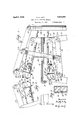
- FIG. 1 is a side elevational view showing a machine constructed in accordance with the principles of my invention
- Fig. 2 is a plan View thereof
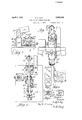
- Fig. 8 is a front elevational view
- Fig. f is a view taken on the line 4-4 of Fig. 5;
- Fig. 5 is a view taken on the line 55 of Fig. 4;
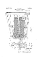
- Fig. 6 is a view of the upper seal placing and afiixing member viewed from the opposite side of Fig. 1;
- Fig. 7 is a side elevational view of a portion of the upper seal placing and aflixing merlnber in position and ready to ailix the sea
- Fig. 8 shows a strip of seal members and the device for accurately positioning said members
- Fig. 9 is a top plan view of a portion of a seal strip
- Fig. 10 is a side view thereof
- Fig. 11 is a View of an upper and lower seal member in position ready to engage the material on which the seal is to be fastened;
- Fig. 12 is a plan view of a lower seal memher.
- Fig. 13 is the top plan view of a seal applied to a material.
- a bed-plate or operating table 10 of suitable size for the work at hand, and which may be supported in any convenient means such as legs 11-11 of proper height and dimensions.
- the height may be such as to enable the operator to stand in front of the table and operate the mechanism either by foot or by other means well known to the art and, therefore, are not herein shown.
- the front part of the table or plate may be supplied with a flange 12.
- I provide a pair of upstanding lugs or ears 13-13 which are provided with a pivot 14 on which is pivotally supported the upper jaw 15 for supplying and positioning the upper seal members.
- Lugs 16-16 are provided each with extension links 1919 in which a pivot pin 20 pivotally supports the lower operating lever 21.
- This operating lever is provided near its mid point with a pivot pin 22 on which the links 2323 are fastened.
- These links extend through openlngs 24 in the bed-plate and are bent outward so as to provide room for the upper and lower jaws to. move freely therebetween.
- a pivot pin 25 is provided at the upper extremity of these links on which the main operating lever 26 is fulcrumed.
- a pivot pin 27 for attachment of the operating bar or rod 28 which rod is operated by the usual foot lever or equivalent, not shown.
- the outer extremity of said main operating lever 26 carries a plunger 29 pivotally connected to said main operating lever 29 by pivot 30.
- the plunger is provided with stop pins 31 and a release pin 32 which cooperate with the plunger seat 33 of the upper jaw member 15.
- the stop pins 31 engage the plunger seat 33 as the plunger 29 closes upon the seal member 45 and thus swings jaw member 15 upon its pivot 14 in the closing position.
- An end plate 34 is fastened on the plunger seat of the jaw member 15 by suitable means such as screws 35. and release pin 32 engages said plate when the plunger moves up, or is opening to swing the jaw member 15 to its open position.
- a cutter plate 36 having a sloping edge 47 (see Fig. 5) which cooperates with the plunger for cutting the'seal members from the strip as the plunger closes upon the seal member 45 and fastens the same upon the goods sealed thereby.
- the cutter plate 36 is held under tension by means of the cutter plate holding spring 37 and a pin 38 limits the movement of the plate.
- a seal strip guide 39 provides a passage for the seal strip member 40 from which the seal members are cut as needed.
- the construction of the lower jaw member 18 is substantially similar to that just described for the upper jaw member 15 and associated parts.
- the lower plunger 29 is pivotally mounted at 30' on the lower operating lever 21. Stop pins 31' and release pins 32 are provided as in the upper plunger and the lower end piece of plunger seat 33 is supplied with an end plate 34 which is held in position by screws 35. lVithin the plunger seat the lower cutter plate 36 is provided which has a sloping cutting edge 47 similar to the edge 47 in the upper cutter plate 36.
- a pin 38 limits the movement of the cutter plate and the cutter holding spring 37 tensions the cutter in an upward direction.
- the upper portion of jaw 18 is provided with a seal strip guide 39 in which is movably held the lower seal strip 40, and from which the lower seal members are cut.
- the jaw like members 15 and 18 serve as supports for. the seal advancing means 50, or 50 for the seal aflixing means or plungers 29 and 29 and cutters 36 and 36.
- Member 15 is further provided with an upper plunger release spring 42 and member 18 with a lower plunger release spring 43. Said release-springs effect positive release of the respective plungers 29 and 29' as the jaw members open.
- I provide suitable seal feeding means such as plate 50 on the upper jaw 15 and a similar plate 50 on the corresponding lower jaw 18.
- Said plates are pivotally mounted at 51 and 51 respectively, and are united by a clevis 52, which is adjustably held by suitable means such as nuts 54 and 54. Said plate members move within the limits permitted by the slots 53 and 53,
- a seal stop mechanism on the upper and lower jaws, which stop mechanism is shown in Figs. 2, l and 8.
- This mechanism comprises a spring member 61 having a chisel edged stop pin 62 which edge engages the notch 63 of the seal strip to hold the seal members in accurate positions on either side of the material to be sealed.
- I find it advantageous to so adjust the sealstrip feeding mechanism as to feed the seal members a trifle too far into the sealing heads and beyond the proper cutting point. Then as the plunger-s and jaw members are brought together and before the seal members are cut, said strips are withdrawn to the position determined by pin 62 of the seal stop mechanism 60. This provision insures accuracy in aligning the seal members on either side of the goods to be sealed and thus provides a tight seal which cannot be removed without breaking the seal or injuring the goods so sealed and protected.
- a seal and tag aflixing machine the combination of a bed-plate having a pair of lugs extending from opposite surfaces of said bed-plate, a plurality of pivots on said lugs, jaw members mounted on said pivots, said jaw members each having a plunger seat, a plunger slidably mounted in said seat, and means for initiating operation of said plnngers one in advance of the other.
- a seal and tag aflixing machine the combination of a bed-plate having a pair of lugs extending from opposite surfaces of said bed-plate, a plurality of pivots on said lugs, jaw members mounted on said pivots, said jaw members each having a plunger seat, a plunger slidably mounted in said seat, means for pivotally supporting said jaw members and said plungers, and means for operating said jaw members one in advance of the other and then operating said plungers.
- a seal and tag affixing machine the combination of a bed-plate having a pair of lugs extending from opposite surfaces of said bed-plate, a plurality of pivots on said lugs, jaw members mounted on said pivots, said jaw members each having a plunger seat, a plunger slidably mounted in said seat, means for pivotally operating said j aw members and plungers to first move said jaw members and plungers in unison and then to slide each of said plungers in its seat, means for advancing seal members into the path of the plunger, and a movable cutter in said plunger seat cooperating with said plunger to sever and position a seal member for sealing a commodity.
- a seal and tag affixing machine the combination of a table having oppositely ex tending lugs, pivots on said lugs, a jaw member mounted in each of said pivots, seal allixing means slidably held by each of said j aw members, operating levers and means for pivotally supporting each of said seal aflixing means on said operating levers, one of said operating levers supported pivotally from said bed-plate, and means for supporting the other of said levers on said first named operating lever.
- a table having lugs thereon extending from opposite sides and swingable supports pivotally mounted on said lugs to swing onto said table from opposite directions, said supports having seal strip passages through which strips of seal members are fed, seal feeding means for advancing said strips of seal members when said supports swing, means for swinging said supports towards each other from opposite sides, and means for afiixing seal members on goods.
- a table having a plurality of lugs extending from opposite sides thereof, seal carrying and seal aflixing members pivotally mounted on said lugs to swing towards said table surfaces, said seal affixing members having lugs which engage said seal carrying members upon the seal affixing moving of said member, levers for operating said seal afiixing members, one of said levers supported pivotally from lugs on said bed-plate, and means for supporting the other of said levers on said first named lever.
- a table having lugs extending from opposite sides thereof and swingable supports having passages for feeding seal members there through onto opposite sides of goods to be sealed, means operative during the opening swing of said swingable supports for advancing said seal members, means for swinging said supports towards each other, and plungers for afiixing said seal members onto said goods after the swinging of said sup ports.
Landscapes
- Engineering & Computer Science (AREA)
- Textile Engineering (AREA)
- Labeling Devices (AREA)
Description
A ril 5, 1932.- D. D. LEVY SEAL OR TAG AFFIXING MACHINE Filed Dec. 7. 1929 3 Sheets-Sheet l lll iv w
April 5, 1932. D. D. LEVY SEAL OR TAG AFFIXING MACHINE Filed Dec. '7, 1929 3 Sheets-Sheet 2 April 5, 1932. D. D. LEVY SEAL OR TAG AFFIXING MACHINE N W M My m Q 2 L M 4% r .1 W 0 a Q X] 9 wm m Patented Apr. 5, 1932 UNITED STATES PATENT OFFICE DUDLEY D. LEVY, OF NEW YORK, IN.Y., ASSIGNOR T0 DUDLEY RESEARCH CORPORA- TION', OF NEW YORK, N. Y., A CORPORATION OF NEW YORK SEAL 0R TAG- AFFIXING MACHINE Application filed December 7, 1929. Serial No. 412,412.
This invention relates to improvements in seal or tag aflixing machines and has for its object the provision of a simple and eflicient machine for permanently afiixing identification seals, or tags, to various articles or commodities such as furs, skins, leathers, textiles, paper compositions and the like, or articles made from the above named and other commodities.
Another object of the invention includes means whereby seal or tag affixing members are attached to the goods in question in such a manner that the edges of the seal members bite into the material itself from opposite sides. The holding members are thereby completely concealed by said seal members and they engage each other in such a manner that it is practically impossible to remove the seal members without damaging the goods or showing marks thereon.
Another object of the invention includes the production of a machine of the type named wherein the moving parts are comparatively few and all parts are strong and substantial so as not to be liable to breakage or to readily get out of order.
A further object includes the provision of means for feeding forward the seal or tag members to a point beyond the sealing position and then retracting said members to the exact or fixed position so as to align the seal members and accurately place them on opposite sides of the material.
Other objects will appear hereinafter and I attain these objects by the construction illustrated in the accompanying drawings, in which Figure 1 is a side elevational view showing a machine constructed in accordance with the principles of my invention;
Fig. 2 is a plan View thereof;
Fig. 8 is a front elevational view;
Fig. f is a view taken on the line 4-4 of Fig. 5;
Fig. 5 is a view taken on the line 55 of Fig. 4;
Fig. 6 is a view of the upper seal placing and afiixing member viewed from the opposite side of Fig. 1;
Fig. 7 is a side elevational view of a portion of the upper seal placing and aflixing merlnber in position and ready to ailix the sea Fig. 8 shows a strip of seal members and the device for accurately positioning said members;
Fig. 9 is a top plan view of a portion of a seal strip;
Fig. 10 is a side view thereof;
Fig. 11 is a View of an upper and lower seal member in position ready to engage the material on which the seal is to be fastened;
Fig. 12 is a plan view of a lower seal memher; and
Fig. 13 is the top plan view of a seal applied to a material.
The same reference characters refer to like parts throughout the several views wherever they appear.
It is one of the prime purposes of my invention'to produce a simple and efficient machine for rapidly and accurately applying seal or tag members which are used by manufacturers and others to identify or seal their goods and which are applied to the goods in such a manner as to make it practically impossible to remove the same without detection. In addition to the functions indicated above the machine is suited also for affixing eyelets as well as for applying seals, tags and labels to goods and commodities for identification, or as a means of safeguarding the same.
To this end I provide a bed-plate or operating table 10 of suitable size for the work at hand, and which may be supported in any convenient means such as legs 11-11 of proper height and dimensions. The height may be such as to enable the operator to stand in front of the table and operate the mechanism either by foot or by other means well known to the art and, therefore, are not herein shown.
The front part of the table or plate may be supplied with a flange 12. At the rear portion thereof I provide a pair of upstanding lugs or ears 13-13 which are provided with a pivot 14 on which is pivotally supported the upper jaw 15 for supplying and positioning the upper seal members.
Immediately beneath lugs 13-13 are companion lugs 1616 extending from the lower portion of the table and in which the pivot journal 17 is provided for pivotally carrying the lower jaw member 18 which supports and positions the lower seal members. The upper and lower jaw members are similar in construction. Lugs 16-16 are provided each with extension links 1919 in which a pivot pin 20 pivotally supports the lower operating lever 21. This operating lever is provided near its mid point with a pivot pin 22 on which the links 2323 are fastened. These links extend through openlngs 24 in the bed-plate and are bent outward so as to provide room for the upper and lower jaws to. move freely therebetween. At the upper extremity of these links a pivot pin 25 is provided on which the main operating lever 26 is fulcrumed. At one end of said operating lever there is provided a pivot pin 27 for attachment of the operating bar or rod 28 which rod is operated by the usual foot lever or equivalent, not shown. The outer extremity of said main operating lever 26 carries a plunger 29 pivotally connected to said main operating lever 29 by pivot 30. The plunger is provided with stop pins 31 and a release pin 32 which cooperate with the plunger seat 33 of the upper jaw member 15. The stop pins 31 engage the plunger seat 33 as the plunger 29 closes upon the seal member 45 and thus swings jaw member 15 upon its pivot 14 in the closing position. An end plate 34 is fastened on the plunger seat of the jaw member 15 by suitable means such as screws 35. and release pin 32 engages said plate when the plunger moves up, or is opening to swing the jaw member 15 to its open position. Within the plunger seat 33 and on the inner side of the plunger 29 there is provided a cutter plate 36 having a sloping edge 47 (see Fig. 5) which cooperates with the plunger for cutting the'seal members from the strip as the plunger closes upon the seal member 45 and fastens the same upon the goods sealed thereby. The cutter plate 36 is held under tension by means of the cutter plate holding spring 37 and a pin 38 limits the movement of the plate. A seal strip guide 39 provides a passage for the seal strip member 40 from which the seal members are cut as needed.
The construction of the lower jaw member 18 is substantially similar to that just described for the upper jaw member 15 and associated parts. The lower plunger 29 is pivotally mounted at 30' on the lower operating lever 21. Stop pins 31' and release pins 32 are provided as in the upper plunger and the lower end piece of plunger seat 33 is supplied with an end plate 34 which is held in position by screws 35. lVithin the plunger seat the lower cutter plate 36 is provided which has a sloping cutting edge 47 similar to the edge 47 in the upper cutter plate 36. A pin 38 limits the movement of the cutter plate and the cutter holding spring 37 tensions the cutter in an upward direction. The upper portion of jaw 18 is provided with a seal strip guide 39 in which is movably held the lower seal strip 40, and from which the lower seal members are cut. It, will be noted that the jaw like members 15 and 18 serve as supports for. the seal advancing means 50, or 50 for the seal aflixing means or plungers 29 and 29 and cutters 36 and 36. Member 15 is further provided with an upper plunger release spring 42 and member 18 with a lower plunger release spring 43. Said release-springs effect positive release of the respective plungers 29 and 29' as the jaw members open.
When a commodity 44 is to be sealed or taggedit is placed upon the table 10 in the position shown in Fig. 4, but, at this time the jaws are open as shown in Fig. 1. The operating bar 28 is then operated by being moved upwards in the direction indicated by the arrow in Fig. 1, and jaw member 15 is brought in contact with the material in position as shown in Fig. 7. During this movement lever 26 is fulcrumed at 25 and the lower member remains stationary until the upper member is brought in contact with the material. Pivot pin 20 now acts as a fulcrum for the lower operating lever 21 which is pulled upwards by straps 23 so as to bring the operating members in contact with the lower surface of the material and in position substantially as indicated by Fig. 4. As the jaws are brought together the upper and lower plungers are moved towards each other and past the cutting edges 47 and 47 to sever the respective upper and lower seal members 45 and 46 thereby bringing the same in sealing relation from opposite sides onto the goods 44. By this movement the outer biting edges 6 of the seal members are brought into biting relation upon the goods and the upper and lower prongs p, p, and p p engage each other at right angles (see Fig. 11) as they cut through the goods and interlock. That is prongs p, p and p 29 have their points turned in enough (when these are cut from 71,) to clinch inwards; said points are also offset to pass each other when clinched. The companion prongs therefore interlock and are completely protected between the seal plate members.
In order to advance the seal members to their proper positions I provide suitable seal feeding means such as plate 50 on the upper jaw 15 and a similar plate 50 on the corresponding lower jaw 18. Said plates are pivotally mounted at 51 and 51 respectively, and are united by a clevis 52, which is adjustably held by suitable means such as nuts 54 and 54. Said plate members move within the limits permitted by the slots 53 and 53,
till
and when moving the seal engaging spring members and 55 advance the upper and lower seal members to new positions. The advancingposition of the plate member 50 is indicated by Fig. 7 and the advanced position of both plates 50 and 50 is indiacted by Fig. 1.
In order to definitely and accurately fix the position of the seal members I provide a seal stop mechanism on the upper and lower jaws, which stop mechanism is shown in Figs. 2, l and 8. This mechanism comprises a spring member 61 having a chisel edged stop pin 62 which edge engages the notch 63 of the seal strip to hold the seal members in accurate positions on either side of the material to be sealed. In practice I find it advantageous to so adjust the sealstrip feeding mechanism as to feed the seal members a trifle too far into the sealing heads and beyond the proper cutting point. Then as the plunger-s and jaw members are brought together and before the seal members are cut, said strips are withdrawn to the position determined by pin 62 of the seal stop mechanism 60. This provision insures accuracy in aligning the seal members on either side of the goods to be sealed and thus provides a tight seal which cannot be removed without breaking the seal or injuring the goods so sealed and protected.
Having now described my invention what I seek to secure by United States Letters Patent is:
1. In a seal and tag allixing machine, the combination of a bed'plate having lugs extending oppositely therefrom, pivots on said lugs, jaw members mounted on said pivots, a plunger slidably mounted in each of said jaw members, and means for operating said jaw members and plungers together and then to slide each plunger in its aw member.
9. A seal and tag aflixing machine, the combination of a bed-plate having a pair of lugs extending from opposite surfaces of said bed-plate, a plurality of pivots on said lugs, jaw members mounted on said pivots, said jaw members each having a plunger seat, a plunger slidably mounted in said seat, and means for initiating operation of said plnngers one in advance of the other.
3. A seal and tag aflixing machine, the combination of a bed-plate having a pair of lugs extending from opposite surfaces of said bed-plate, a plurality of pivots on said lugs, jaw members mounted on said pivots, said jaw members each having a plunger seat, a plunger slidably mounted in said seat, means for pivotally supporting said jaw members and said plungers, and means for operating said jaw members one in advance of the other and then operating said plungers.
4. A seal and tag affixing machine, the combination of a bed-plate having a pair of lugs extending from opposite surfaces of said bed-plate, a plurality of pivots on said lugs, jaw members mounted on said pivots, said jaw members each having a plunger seat, a plunger slidably mounted in said seat, means for pivotally operating said j aw members and plungers to first move said jaw members and plungers in unison and then to slide each of said plungers in its seat, means for advancing seal members into the path of the plunger, and a movable cutter in said plunger seat cooperating with said plunger to sever and position a seal member for sealing a commodity.
5. In a seal and tag affixing machine, the combination of a table having oppositely ex tending lugs, pivots on said lugs, a jaw member mounted in each of said pivots, seal allixing means slidably held by each of said j aw members, operating levers and means for pivotally supporting each of said seal aflixing means on said operating levers, one of said operating levers supported pivotally from said bed-plate, and means for supporting the other of said levers on said first named operating lever.
6. In a seal and tag affixing machine, a table having lugs thereon extending from opposite sides and swingable supports pivotally mounted on said lugs to swing onto said table from opposite directions, said supports having seal strip passages through which strips of seal members are fed, seal feeding means for advancing said strips of seal members when said supports swing, means for swinging said supports towards each other from opposite sides, and means for afiixing seal members on goods.
7. In a seal and tag aflixing machine, a table having a plurality of lugs extending from opposite sides thereof, seal carrying and seal aflixing members pivotally mounted on said lugs to swing towards said table surfaces, said seal affixing members having lugs which engage said seal carrying members upon the seal affixing moving of said member, levers for operating said seal afiixing members, one of said levers supported pivotally from lugs on said bed-plate, and means for supporting the other of said levers on said first named lever.
8. In a seal and tag aflixing machine, a table having lugs extending from opposite sides thereof and swingable supports having passages for feeding seal members there through onto opposite sides of goods to be sealed, means operative during the opening swing of said swingable supports for advancing said seal members, means for swinging said supports towards each other, and plungers for afiixing said seal members onto said goods after the swinging of said sup ports.
In testimony whereof I have hereunto set my hand on this 29th day of November, A. D.
DUDLEY D. LEVY.
Priority Applications (1)
| Application Number | Priority Date | Filing Date | Title |
|---|---|---|---|
| US412412A US1852426A (en) | 1929-12-07 | 1929-12-07 | Seal or tag affixing machine |
Applications Claiming Priority (1)
| Application Number | Priority Date | Filing Date | Title |
|---|---|---|---|
| US412412A US1852426A (en) | 1929-12-07 | 1929-12-07 | Seal or tag affixing machine |
Publications (1)
| Publication Number | Publication Date |
|---|---|
| US1852426A true US1852426A (en) | 1932-04-05 |
Family
ID=23632857
Family Applications (1)
| Application Number | Title | Priority Date | Filing Date |
|---|---|---|---|
| US412412A Expired - Lifetime US1852426A (en) | 1929-12-07 | 1929-12-07 | Seal or tag affixing machine |
Country Status (1)
| Country | Link |
|---|---|
| US (1) | US1852426A (en) |
-
1929
- 1929-12-07 US US412412A patent/US1852426A/en not_active Expired - Lifetime
Similar Documents
| Publication | Publication Date | Title |
|---|---|---|
| US3151583A (en) | Shiftable work carriage for a sewing machine | |
| US1852426A (en) | Seal or tag affixing machine | |
| US1988791A (en) | Sheet-register | |
| US3357618A (en) | Tag attaching machine | |
| US2452856A (en) | Material handling device | |
| US1023883A (en) | Automatic pin-ticketing machine. | |
| US1263535A (en) | Feeding device for stay-applying machines. | |
| US1889250A (en) | Marking machine | |
| US2672251A (en) | Label applying machine | |
| US3382687A (en) | Automatic apparatus for folding leather pieces | |
| US3562828A (en) | Automatic lasting machines | |
| US1642386A (en) | Apparatus for operating upon labels | |
| US1847841A (en) | Machine for affixing identification seals or tags | |
| US1910633A (en) | Nail guiding means | |
| US1203932A (en) | Stamp-affixing machine. | |
| US1552554A (en) | Blank-operated mechanism | |
| US2895388A (en) | Machine for affixing identification tags | |
| US1854977A (en) | Label cutting and folding machine | |
| US2281896A (en) | Marking machine | |
| US2478115A (en) | Tagging device | |
| US2077531A (en) | Thread cutting device for buttonhole and similar sewing machines | |
| US1801250A (en) | Work holder for slicing machines | |
| US3001457A (en) | Jaw type heat sealing machines | |
| US1396406A (en) | Tagging-machine | |
| US2265607A (en) | Buckle attaching machine |