US1852403A - Ammunition for cannons - Google Patents
Ammunition for cannons Download PDFInfo
- Publication number
- US1852403A US1852403A US517036A US51703631A US1852403A US 1852403 A US1852403 A US 1852403A US 517036 A US517036 A US 517036A US 51703631 A US51703631 A US 51703631A US 1852403 A US1852403 A US 1852403A
- Authority
- US
- United States
- Prior art keywords
- projectile
- casing
- tail piece
- shell
- rear end
- Prior art date
- Legal status (The legal status is an assumption and is not a legal conclusion. Google has not performed a legal analysis and makes no representation as to the accuracy of the status listed.)
- Expired - Lifetime
Links
- 239000007789 gas Substances 0.000 description 15
- 238000012856 packing Methods 0.000 description 13
- 208000035388 Ring chromosome 22 syndrome Diseases 0.000 description 7
- 230000000087 stabilizing effect Effects 0.000 description 5
- 238000010276 construction Methods 0.000 description 4
- 239000000843 powder Substances 0.000 description 3
- 238000007789 sealing Methods 0.000 description 3
- 239000000945 filler Substances 0.000 description 2
- 238000012986 modification Methods 0.000 description 2
- 230000004048 modification Effects 0.000 description 2
- RYGMFSIKBFXOCR-UHFFFAOYSA-N Copper Chemical compound [Cu] RYGMFSIKBFXOCR-UHFFFAOYSA-N 0.000 description 1
- 229910000831 Steel Inorganic materials 0.000 description 1
- 230000004308 accommodation Effects 0.000 description 1
- 238000004873 anchoring Methods 0.000 description 1
- CRQQGFGUEAVUIL-UHFFFAOYSA-N chlorothalonil Chemical compound ClC1=C(Cl)C(C#N)=C(Cl)C(C#N)=C1Cl CRQQGFGUEAVUIL-UHFFFAOYSA-N 0.000 description 1
- 229910052802 copper Inorganic materials 0.000 description 1
- 239000010949 copper Substances 0.000 description 1
- 230000000694 effects Effects 0.000 description 1
- 239000002360 explosive Substances 0.000 description 1
- 239000000203 mixture Substances 0.000 description 1
- 235000002020 sage Nutrition 0.000 description 1
- 230000006641 stabilisation Effects 0.000 description 1
- 238000011105 stabilization Methods 0.000 description 1
- 239000010959 steel Substances 0.000 description 1
Images
Classifications
-
- F—MECHANICAL ENGINEERING; LIGHTING; HEATING; WEAPONS; BLASTING
- F42—AMMUNITION; BLASTING
- F42B—EXPLOSIVE CHARGES, e.g. FOR BLASTING, FIREWORKS, AMMUNITION
- F42B10/00—Means for influencing, e.g. improving, the aerodynamic properties of projectiles or missiles; Arrangements on projectiles or missiles for stabilising, steering, range-reducing, range-increasing or fall-retarding
- F42B10/32—Range-reducing or range-increasing arrangements; Fall-retarding means
- F42B10/48—Range-reducing, destabilising or braking arrangements, e.g. impact-braking arrangements; Fall-retarding means, e.g. balloons, rockets for braking or fall-retarding
- F42B10/56—Range-reducing, destabilising or braking arrangements, e.g. impact-braking arrangements; Fall-retarding means, e.g. balloons, rockets for braking or fall-retarding of parachute or paraglider type
Definitions
- the present invention relates to ammunition of the type used in short rcnge guns, adapted for various uses and particularly in connection with the United States Coast Guard wherein shells may be projected from the gun at short ranges.
- An object of the present invention is to provide a shell of this type which is elongated necessarily for the accommodation of a parachute and a flare candle and which is necessarily of such length that it cannot be stabilized merely by means of rotation.
- the action of rotation in this type of shell is also hard to obtain incident to the slow velocity at which it is necessary to fire the projectile and furthermore the reliabl opening of the parachute would be diflicult to obtain with conventional projectiles stabilized by rotation.
- the shell .of this invention is adapted particularly for use with a smooth barrel gun and embodies peculiar characteristics for stabilizing the projectile during flight.
- a further object of the invention is to provide a construction of projectile which is sealed within the smooth barrel during projection therefrom, which seal is expansible under pressure of the gas and which will not affect the stabilization of the projectile during flight.
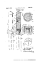
- Figure 1 is a side elevation of a projectile constructed according to the present invention.
- Figure 2 is a longitudinal central section taken through thesame.
- Figure 3 is a rear end elevation of the projectile, showing the tail fin.
- Figure 4 is a fragmentary enlarged section taken longitudinally through the intermediate portion of the projectile, showing the 0 gas seal carried by the projectile and in its relation to the smooth barrel of a gun, and
- Figure 5 is a transverse section taken through the same on the line 55 of Figure 4:.
- the projectile comprises a casing 10 of suitable length to house a parachute 11 in its forward end and the cords or shrouds 12 of the parachute which are suitably folded at one side of the parachute 11 as clearly shown in Figure 2.
- the cords or shrouds 12 are connected to a fiare candle 13 of any approved composition and which is housed in the inner end of the shell 10 and which is connected by means of a cord 14 to the shrouds 12, in the usual manner.
- a felt wad or backing disc 15 is seated against the rear end of the flare candle l3 and is apertured in the usual manner at its central portion, and is covered 'by a steel thrust disc 16 having central perforations therethrough for opening through the pad 15 and which supports at its rear side a quantity of black powder 17 or the like into which is inserted the forward end of a fuse tube 18, the latter containing a slow burning time train.
- the tube 18 projects rearwardly from the shell 10 and into a tail piece 19 which provides substantially a continuation of the casing or shell 10 but which is suitably reduced and threaded for detachable engagement in the rear end of the shell 10.
- the tail piece 19, adjacent its forward threaded portion is provided with an annular groove 20 which is separated from the threaded portion by an annular shoulder 21.
- a copper packing ring 22 Seated above the shoulder 21 is a copper packing ring 22 which has its forward edge portion turned inwardly to provide an attaching flange 23 adapted to be pinched between the rear end of the shell 10 and the shoulder 21 for anchoring the forward edge portion of the packing ring 22 to the projectile.
- the rear edge portion of the packing ring 22 is disposed in spaced relation concentrically about the groove 20 and terminates in spaced relation to the rear shoulder of the groove so as to provide between the shoulder and the rear edge of the packing ring a gas opening 24 providing a passage I through which the gas-es of expulsion in a' gases of expulsion may expand into the pas-- sage beneath or within the ring 22 to effect the expansion thereof.
- the ring 22 'isthus held by pressure of the gases against the inner side of the barrel 25.
- the tail piece 19 is provided, substantially throughout its length, with a pair of crossed fins 26 which, as shown in Figure 3, are disposed at right angles to each other and which intersect at the axis of the tail piece or projectile and hence provide ample plane surfaces for maintaining the projectile in the desired straight line flight.
- the tail piece 19 isthus given a substantially fluted structure and the fuse tube 18 projects rearwardly into and through the forward portion of the tail piece 19 and opens into one of the lateral recesses in the tail piece, as clearly shown in Figures 2 and 3, so that the expanding and burning gases of'projection may additionally serve the function of igniting-the powder in the fuse tube 18.
- the forward 'end of the shell or casing 10 is closed by a nose piece 27 of suitable configuration such as shown, wherein'the nose piece is rounded.
- the fins 26 When the projectile is discharged from the barrel 25 the fins 26 present plane surfaces disposed at right angles to each other for holding the projectile in a true straight line path.
- the structure therefore eliminates the qualities incorporated'by stabilizing a projectile by rotation.
- a projectile comprising a casing, a tail piece connected to the rear end of the casing and having axially intersecting fins extending lengthwise of the tail piece, filling within the shell casing, ignition means in the casing for the filling and including a fuse mem'ber projecting rearwardly through the tail piece and opening at the side of the latter between adjacent fins, and a gas sealing ring carried by the casing and flaring rearwardly over the forward end of the tail piece for sealing the projectile in a gun barrel and admitting passage of the gases of expulsion against the inner side of the ring for expanding the same against the wall of the barrel and admitting free access of said gases of expulsion to the fuse member for igniting said filling.
- a projectile comprising a casing, a filling in said casing, means mounted inthe rear end of the casing for the ignition of said filling, a fuse tube, a tail piece detachably mounted upon the rear end of the casing and having anopening therethrough for receiving the tube, said tube being exposedat one side of the tail piece, said tail piece having lengthwise extending and axially intersecting fins for stabilizing the projectile in flight, and an expansible packing ring anchored at its forward edge portion between the casing and the tail piece and flaring rearwardly therefrom to provide a passage at the inner side of the packing ring for the reception of the expanding gases of projection in a gun barrel to expand the packing ring against the inner wall of the gun barrel and seal the projectile therein.
- a projectile comprising a casing, a tail piece threaded into the rear end of the casing and provided adjacent its threaded portion with an annular groove and with an annular shoulder atthe forward side of the groove, an expansible packing ring having its forward edge portion inturned and pinched between said shoulder of the groove and the rear end of the casing to hold the packing ring inspaced concentric relation about the groove, filling in the casing, ignition means for the filling in the rear end of the casing and including a fuse tube projecting rear- Wardly through the tail piece, said tail piece having a fluted exterior construction for exposing the rear end ofthe fuse tube and providing longitudinal plane surfaces for stabilizing the projectile in flight.
- a projectile comprising a shell, filling in the shell, a detachable plug closing the forward end of the shell, ignition means for the shell filling mounted inthe rear end of the shell and including a fuse tube projecting rearwardly from the shell, a tail piece fitting in the rear end of the shell and projecting therefrom, an expansib'le packing member clamped between the rear end of the shell and the forward end of the tail piece 5 and flaring rearwardly over the latter, said tail piece having an annular groove beneath said packing ring for the reception of gases of projection to expand the packing ring against the inner wall of a gun barrel, said tail piece having lengthwise extending and axially intersecting fins providing flutes at the sides of the tail piece and presenting plane surfaces at angles to one another for stabilizing the projectile in flight.
- a projectile comprising a casing, a tail piece threaded into the rear end of the easing and provided adjacent its threaded portion with an annular groove and with an annular shoulder at the forward side of the groove, an expansible packing ring having its forward edge portion inturned and pinched between said shoulder of the groove and the rear end of the casing, a filler in the casing, and ignition means for the filler car- 25 ried by the shell.
Landscapes
- Physics & Mathematics (AREA)
- Fluid Mechanics (AREA)
- Engineering & Computer Science (AREA)
- General Engineering & Computer Science (AREA)
- Toys (AREA)
Description
' April 5, 1932.
L. L. DRIGGS, JR, ET AL AMMUNITION FOR GANNONS Filed Feb. 19, 1931 v Qwwntow L. 15 D?" 6 Jr:
Patented Apr. 5, 1232 rears LOUIS L. DRIGGS, JR, OF NEW ROCHELLE, AND HENRY B. FABER, OF NEW YORK, N. Y.
JEili'IlVITJN'I'JIION FOR CANNONS Application filed February 19, 1931.
The present invention relates to ammunition of the type used in short rcnge guns, adapted for various uses and particularly in connection with the United States Coast Guard wherein shells may be projected from the gun at short ranges.
An object of the present invention is to provide a shell of this type which is elongated necessarily for the accommodation of a parachute and a flare candle and which is necessarily of such length that it cannot be stabilized merely by means of rotation. The action of rotation in this type of shell is also hard to obtain incident to the slow velocity at which it is necessary to fire the projectile and furthermore the reliabl opening of the parachute would be diflicult to obtain with conventional projectiles stabilized by rotation. To overcome these disadvantages the shell .of this invention is adapted particularly for use with a smooth barrel gun and embodies peculiar characteristics for stabilizing the projectile during flight.
A further object of the invention is to provide a construction of projectile which is sealed within the smooth barrel during projection therefrom, which seal is expansible under pressure of the gas and which will not affect the stabilization of the projectile during flight.
With the foregoing and other objects in view, the invention will be more fully described hereinafter, and'will be more particularly pointed out in the claims appended hereto.
In the drawings, wherein like symbols refer to like or corresponding parts throughout the several views.
Figure 1 is a side elevation of a projectile constructed according to the present invention.
Figure 2 is a longitudinal central section taken through thesame.
Figure 3 is a rear end elevation of the projectile, showing the tail fin.
Figure 4 is a fragmentary enlarged section taken longitudinally through the intermediate portion of the projectile, showing the 0 gas seal carried by the projectile and in its relation to the smooth barrel of a gun, and
Serial No. 517,036.
Figure 5 is a transverse section taken through the same on the line 55 of Figure 4:.
Referring to the drawings, the projectile comprises a casing 10 of suitable length to house a parachute 11 in its forward end and the cords or shrouds 12 of the parachute which are suitably folded at one side of the parachute 11 as clearly shown in Figure 2. The cords or shrouds 12 are connected to a fiare candle 13 of any approved composition and which is housed in the inner end of the shell 10 and which is connected by means of a cord 14 to the shrouds 12, in the usual manner.
A felt wad or backing disc 15 is seated against the rear end of the flare candle l3 and is apertured in the usual manner at its central portion, and is covered 'by a steel thrust disc 16 having central perforations therethrough for opening through the pad 15 and which supports at its rear side a quantity of black powder 17 or the like into which is inserted the forward end of a fuse tube 18, the latter containing a slow burning time train.
The tube 18 projects rearwardly from the shell 10 and into a tail piece 19 which provides substantially a continuation of the casing or shell 10 but which is suitably reduced and threaded for detachable engagement in the rear end of the shell 10. The tail piece 19, adjacent its forward threaded portion is provided with an annular groove 20 which is separated from the threaded portion by an annular shoulder 21.
Seated above the shoulder 21 is a copper packing ring 22 which has its forward edge portion turned inwardly to provide an attaching flange 23 adapted to be pinched between the rear end of the shell 10 and the shoulder 21 for anchoring the forward edge portion of the packing ring 22 to the projectile. The rear edge portion of the packing ring 22 is disposed in spaced relation concentrically about the groove 20 and terminates in spaced relation to the rear shoulder of the groove so as to provide between the shoulder and the rear edge of the packing ring a gas opening 24 providing a passage I through which the gas-es of expulsion in a' gases of expulsion may expand into the pas-- sage beneath or within the ring 22 to effect the expansion thereof. The ring 22 'isthus held by pressure of the gases against the inner side of the barrel 25.
In order to stabilize the projectile in flight, the tail piece 19 is provided, substantially throughout its length, with a pair of crossed fins 26 which, as shown in Figure 3, are disposed at right angles to each other and which intersect at the axis of the tail piece or projectile and hence provide ample plane surfaces for maintaining the projectile in the desired straight line flight. The tail piece 19 isthus given a substantially fluted structure and the fuse tube 18 projects rearwardly into and through the forward portion of the tail piece 19 and opens into one of the lateral recesses in the tail piece, as clearly shown in Figures 2 and 3, so that the expanding and burning gases of'projection may additionally serve the function of igniting-the powder in the fuse tube 18.
The forward 'end of the shell or casing 10 is closed by a nose piece 27 of suitable configuration such as shown, wherein'the nose piece is rounded.
From the above'it is thought the operation will'be clear as the projectile when mounted in a smooth barrel gun is sealed within the barrel by means of'the ring-22'and when the gun is fired the burning and expanding gases not only ignite the powder in the fuse tube 18 to light the fuse but the gases pass through the annular passage 22 into the groove 20 beneath the sealing'ring 22, expanding the latter firmly against the inner face of the barrel 25' and preventing excess loss of the gases from behind the projectile.
When the projectile is discharged from the barrel 25 the fins 26 present plane surfaces disposed at right angles to each other for holding the projectile in a true straight line path. The structure therefore eliminates the qualities incorporated'by stabilizing a projectile by rotation.
Although the foregoing description covers the specific construction of a parachute flare projectile other types of shell filling may be employed such as, high explosive, gas, etc. without departing from the spirit of the invention, and it is obvious that variousother changes and modifications may be made in the details of construction and design of the an above specifically described embodiment of this invention without departing from the spirit thereof, such changes and modifications being restricted only by the scope of the following claims.
What is claimed is 1. A projectile, comprising a casing, a tail piece connected to the rear end of the casing and having axially intersecting fins extending lengthwise of the tail piece, filling within the shell casing, ignition means in the casing for the filling and including a fuse mem'ber projecting rearwardly through the tail piece and opening at the side of the latter between adjacent fins, and a gas sealing ring carried by the casing and flaring rearwardly over the forward end of the tail piece for sealing the projectile in a gun barrel and admitting passage of the gases of expulsion against the inner side of the ring for expanding the same against the wall of the barrel and admitting free access of said gases of expulsion to the fuse member for igniting said filling.
2. A projectile, comprising a casing, a filling in said casing, means mounted inthe rear end of the casing for the ignition of said filling, a fuse tube, a tail piece detachably mounted upon the rear end of the casing and having anopening therethrough for receiving the tube, said tube being exposedat one side of the tail piece, said tail piece having lengthwise extending and axially intersecting fins for stabilizing the projectile in flight, and an expansible packing ring anchored at its forward edge portion between the casing and the tail piece and flaring rearwardly therefrom to provide a passage at the inner side of the packing ring for the reception of the expanding gases of projection in a gun barrel to expand the packing ring against the inner wall of the gun barrel and seal the projectile therein.
3'. A projectile, comprising a casing, a tail piece threaded into the rear end of the casing and provided adjacent its threaded portion with an annular groove and with an annular shoulder atthe forward side of the groove, an expansible packing ring having its forward edge portion inturned and pinched between said shoulder of the groove and the rear end of the casing to hold the packing ring inspaced concentric relation about the groove, filling in the casing, ignition means for the filling in the rear end of the casing and including a fuse tube projecting rear- Wardly through the tail piece, said tail piece having a fluted exterior construction for exposing the rear end ofthe fuse tube and providing longitudinal plane surfaces for stabilizing the projectile in flight.
l. A projectile comprising a shell, filling in the shell, a detachable plug closing the forward end of the shell, ignition means for the shell filling mounted inthe rear end of the shell and including a fuse tube projecting rearwardly from the shell, a tail piece fitting in the rear end of the shell and projecting therefrom, an expansib'le packing member clamped between the rear end of the shell and the forward end of the tail piece 5 and flaring rearwardly over the latter, said tail piece having an annular groove beneath said packing ring for the reception of gases of projection to expand the packing ring against the inner wall of a gun barrel, said tail piece having lengthwise extending and axially intersecting fins providing flutes at the sides of the tail piece and presenting plane surfaces at angles to one another for stabilizing the projectile in flight.
5. A projectile comprising a casing, a tail piece threaded into the rear end of the easing and provided adjacent its threaded portion with an annular groove and with an annular shoulder at the forward side of the groove, an expansible packing ring having its forward edge portion inturned and pinched between said shoulder of the groove and the rear end of the casing, a filler in the casing, and ignition means for the filler car- 25 ried by the shell.
LOUIS L. DRIGGS, JR. HENRY B. FABER.
Priority Applications (1)
| Application Number | Priority Date | Filing Date | Title |
|---|---|---|---|
| US517036A US1852403A (en) | 1931-02-19 | 1931-02-19 | Ammunition for cannons |
Applications Claiming Priority (1)
| Application Number | Priority Date | Filing Date | Title |
|---|---|---|---|
| US517036A US1852403A (en) | 1931-02-19 | 1931-02-19 | Ammunition for cannons |
Publications (1)
| Publication Number | Publication Date |
|---|---|
| US1852403A true US1852403A (en) | 1932-04-05 |
Family
ID=24058117
Family Applications (1)
| Application Number | Title | Priority Date | Filing Date |
|---|---|---|---|
| US517036A Expired - Lifetime US1852403A (en) | 1931-02-19 | 1931-02-19 | Ammunition for cannons |
Country Status (1)
| Country | Link |
|---|---|
| US (1) | US1852403A (en) |
Cited By (1)
| Publication number | Priority date | Publication date | Assignee | Title |
|---|---|---|---|---|
| US3479954A (en) * | 1968-05-07 | 1969-11-25 | Thiokol Chemical Corp | Igniter system for illuminating compositions |
-
1931
- 1931-02-19 US US517036A patent/US1852403A/en not_active Expired - Lifetime
Cited By (1)
| Publication number | Priority date | Publication date | Assignee | Title |
|---|---|---|---|---|
| US3479954A (en) * | 1968-05-07 | 1969-11-25 | Thiokol Chemical Corp | Igniter system for illuminating compositions |
Similar Documents
| Publication | Publication Date | Title |
|---|---|---|
| US2344957A (en) | Pistol rocket | |
| US3911823A (en) | Pyrotechnic devices | |
| US2297130A (en) | Drag preventing means for projectiles | |
| US3780658A (en) | Undersized-caliber projectile with detachable sabot | |
| US2324346A (en) | Projectile for firearms | |
| US2251918A (en) | Antiaircraft projectile | |
| US1360602A (en) | Projectile | |
| US2323303A (en) | Incendiary bullet | |
| US1852403A (en) | Ammunition for cannons | |
| US2359515A (en) | Variable range projectile | |
| US1417460A (en) | Fixed ammunition | |
| US2263585A (en) | Float light and smoke bomb | |
| US2115608A (en) | Projectile | |
| US3274935A (en) | Practice ammunition | |
| US3494285A (en) | Tracer projectile for rifles | |
| US3298311A (en) | Smoke flare | |
| US1166360A (en) | Gun cartridge and projectile. | |
| US1309982A (en) | Careieb-shell | |
| US2120246A (en) | Pyrotechnic device | |
| US2057953A (en) | Mortar projectile | |
| US2269582A (en) | Signal flare | |
| US2304060A (en) | Projectile | |
| US1322083A (en) | X a aerial torpedo | |
| US1817503A (en) | Aerial flare | |
| US2369924A (en) | Explosive projectile |