US1852339A - Slip rotation for rock drills - Google Patents
Slip rotation for rock drills Download PDFInfo
- Publication number
- US1852339A US1852339A US287510A US28751028A US1852339A US 1852339 A US1852339 A US 1852339A US 287510 A US287510 A US 287510A US 28751028 A US28751028 A US 28751028A US 1852339 A US1852339 A US 1852339A
- Authority
- US
- United States
- Prior art keywords
- ring
- ratchet
- wedges
- rotation
- piston
- Prior art date
- Legal status (The legal status is an assumption and is not a legal conclusion. Google has not performed a legal analysis and makes no representation as to the accuracy of the status listed.)
- Expired - Lifetime
Links
- 239000011435 rock Substances 0.000 title 1
- 229910000831 Steel Inorganic materials 0.000 description 5
- 239000010959 steel Substances 0.000 description 5
- 230000002159 abnormal effect Effects 0.000 description 4
- 238000010276 construction Methods 0.000 description 4
- 238000005553 drilling Methods 0.000 description 4
- 230000000694 effects Effects 0.000 description 1
- 230000002093 peripheral effect Effects 0.000 description 1
Images

Classifications
-
- E—FIXED CONSTRUCTIONS
- E21—EARTH OR ROCK DRILLING; MINING
- E21B—EARTH OR ROCK DRILLING; OBTAINING OIL, GAS, WATER, SOLUBLE OR MELTABLE MATERIALS OR A SLURRY OF MINERALS FROM WELLS
- E21B6/00—Drives for drilling with combined rotary and percussive action
- E21B6/06—Drives for drilling with combined rotary and percussive action the rotation being intermittent, e.g. obtained by ratchet device
-
- Y—GENERAL TAGGING OF NEW TECHNOLOGICAL DEVELOPMENTS; GENERAL TAGGING OF CROSS-SECTIONAL TECHNOLOGIES SPANNING OVER SEVERAL SECTIONS OF THE IPC; TECHNICAL SUBJECTS COVERED BY FORMER USPC CROSS-REFERENCE ART COLLECTIONS [XRACs] AND DIGESTS
- Y10—TECHNICAL SUBJECTS COVERED BY FORMER USPC
- Y10S—TECHNICAL SUBJECTS COVERED BY FORMER USPC CROSS-REFERENCE ART COLLECTIONS [XRACs] AND DIGESTS
- Y10S403/00—Joints and connections
- Y10S403/08—Radially acting cam or eccentric
-
- Y—GENERAL TAGGING OF NEW TECHNOLOGICAL DEVELOPMENTS; GENERAL TAGGING OF CROSS-SECTIONAL TECHNOLOGIES SPANNING OVER SEVERAL SECTIONS OF THE IPC; TECHNICAL SUBJECTS COVERED BY FORMER USPC CROSS-REFERENCE ART COLLECTIONS [XRACs] AND DIGESTS
- Y10—TECHNICAL SUBJECTS COVERED BY FORMER USPC
- Y10T—TECHNICAL SUBJECTS COVERED BY FORMER US CLASSIFICATION
- Y10T403/00—Joints and connections
- Y10T403/70—Interfitted members
- Y10T403/7009—Rotary binding cam or wedge
- Y10T403/7011—Radially interposed shim or bushing
- Y10T403/7013—Arcuate slip
-
- Y—GENERAL TAGGING OF NEW TECHNOLOGICAL DEVELOPMENTS; GENERAL TAGGING OF CROSS-SECTIONAL TECHNOLOGIES SPANNING OVER SEVERAL SECTIONS OF THE IPC; TECHNICAL SUBJECTS COVERED BY FORMER USPC CROSS-REFERENCE ART COLLECTIONS [XRACs] AND DIGESTS
- Y10—TECHNICAL SUBJECTS COVERED BY FORMER USPC
- Y10T—TECHNICAL SUBJECTS COVERED BY FORMER US CLASSIFICATION
- Y10T74/00—Machine element or mechanism
- Y10T74/15—Intermittent grip type mechanical movement
- Y10T74/1526—Oscillation or reciprocation to intermittent unidirectional motion
- Y10T74/1527—Screw and nut devices
Definitions
- the present invention relates to mechanism for effecting the rotation of a reciprocatory drill for the purpose of rotating the drill steel.
- the object is to provide novel, simple and effective means that will insure proper rotation of the piston and steel, but will permi t the slipping of the ratchet mechanism in case the drill becomes stuck or held against rotation, thereby preventing the rotation of the tool body.
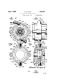
- Figure 1 is a. longitudinal sectional view through a portion of a drilling apparatus, equipped with the novel means.
- Figure 2 is a cross sectional view on the line Q-2 of Figure 1.
- Figure 3 is a side elevation of the portion of the cylinder member that houses the ratchet mechanism.
- Figure 4 is a detail view in elevation of the clutch wedges.
- Figure 5 is an edge view of the same.
- Figure 6 is a cross sectional view showing a modified form of construction.
- Figure 7 is a sectional View on the line 77 of Figure 6.
- a cylinder member 8 is employed, in which is a reciproiatory piston 9 that operates on. a drill steel and effects the rotation thereof, being itself rotated in a manner well understood.
- a ride bar 10 having a slidable inter-fitting engagement with a nut 11 secured in the rear end of the piston 9.
- This rifle bar is provided at its rear end with a ratchet head 12 located in a chamber 18 formed in the rear end of the cyliud er member 8.
- a ratchet ring 141 Surrounding the ratchet head 12 a ratchet ring 141., also located in the chamber 13. and having internal teeth 15.
- the ratchet head 12 is provided with ,.-resscd pawls 16 that are adapted 2 the ratchet ring. If the ratchet ring 1 held against rotation as the piston rrciprocates. the pants 16 will ride the teeth when said piston moves in one direction and engage behind them when the piston mores n the opposite direction, thereby rotating said piston step-by-step.
- Means are provided for frictionally holding the ratchet ring 14 against rotation.
- the inner wedges 17 have their inner faces curved to conform to the periphery of the ratchet ring 14 and frictionally bear against the same.
- the outer wedges 18 are interposed between said wedges 17 and the peripheral wall of the chamber 13. These latter wedges 18 have their larger ends abutted against stop pins 19.
- the larger ends of the inner clutch wedges 17 are engaged by the inner ends of adjusting bolts 20 tangentially disposed and threaded into enlargements 21 formed on the rear end of the cylinder member.
- the outer ends of the bolts 20 are provided with kerfs 22 to receive a screw driver or other tool and jamb nuts 23 are preferably provided to hold said bolts against accidental turning.
- FIGS 6 and 7 a slightly modified form of construction is illustrated.
- the cylinder member is designated 24 and the ratchet ring is shown at 25.
- the wedges are in sets and are designated respectively 26 and 27. So far the structure is substantially the same as that above described.
- adjusting plugs 28 are employed that are radially disposed and have tapered inner ends 29 that are interposed between and bear against the inner clutch wedge 26 of one set, and the outer wedge 27 of the other set. By moving these plugs inwardly, frictional pressure is brought between the inner clutch wedges 26 and the periphery of the clutch ring 25.
- the plugs in this instance are held against rotation by cross pins 30 engaged in the tool-receiving slots 31 formed in the outer ends of said plugs 28'.
- her having a chamber for ratchet mechanism, and a reciprocatory piston operating in the cylinder member, and being capable of rotary movement therein, of ratchet mechas nism in the chamber for effecting a step-bystep rotation of the piston and including a rotatable ring, oppositely disposed coacting wedge members interposed between the ring and chamber wall for holding the ring against rotation until abnormal force operates on said ring to rotate it and thereby make the ratchet mechanism inefiective, and a screw threaded in the cylinder member and bearing against one of the wedges for relatively moving the wedges to vary'their frictional pressure against the ring.
- the combinatien with a cylinder member and a piston operating therein and capable of rotary movement also, of mechanism for effecting the rotation of the piston including a rifle bar having a ratchet head, a ratchet ring surrounding the head and rotatable, sets of oppositely disposed overlapping wedges, the inner wedges being curved and fitting the periphery of the ratchet ring, and means for relatively moving the wedges.
- a rifle bar having a ratchet head.
- a ratchet ring surrounding the head and rotatable, pawls for connecting the head and ring, a pair of oppositely disposed wedges positioned between the ratchet ring and cylinder, one of which bears against the ring to hold it against rotation under normal drilling conditions, a second set of oppositely disposed wedges engageable by the first set and one of which bears against the ring to hold it against rotation, and means disposed within each set of wedges for varying their friction al engagement with the ratchet ring.
Landscapes
- Life Sciences & Earth Sciences (AREA)
- Engineering & Computer Science (AREA)
- Geology (AREA)
- Mining & Mineral Resources (AREA)
- Physics & Mathematics (AREA)
- Environmental & Geological Engineering (AREA)
- Fluid Mechanics (AREA)
- General Life Sciences & Earth Sciences (AREA)
- Geochemistry & Mineralogy (AREA)
- Drilling And Exploitation, And Mining Machines And Methods (AREA)
Description
April 5, 1932. 5 H E SLIP ROTATION FOR ROCK DRILLS Filed June 22, 1928 2 Sheets-Sheet l gwwmtoz EH1? TON 51/55 73 April 1932. B. R SHEETS 1,852,339
SLIP ROTATION FOR ROCK DRILLS Filed June 22. 1928 2 SheetsSheet 2 28 gwve'ntg Q/Wi" Patented Apr. 5, 1932 UNITEi'E STATES PATENT orrics BARTON It. SHEETS, OF DENVER, COLORADO, ASSIGNOR 'IO GARDNER-DENVER COM- FBI-QTY, OF DENVER, COLORADO, A CORPORATION OF DELAWARE SLIP ROTATION FOR ROCK DRILLS Application filed June 22, 1928.
The present invention relates to mechanism for effecting the rotation of a reciprocatory drill for the purpose of rotating the drill steel.
The object is to provide novel, simple and effective means that will insure proper rotation of the piston and steel, but will permi t the slipping of the ratchet mechanism in case the drill becomes stuck or held against rotation, thereby preventing the rotation of the tool body.
In the accompanying drawings:
Figure 1 is a. longitudinal sectional view through a portion of a drilling apparatus, equipped with the novel means.
Figure 2 is a cross sectional view on the line Q-2 of Figure 1.
Figure 3 is a side elevation of the portion of the cylinder member that houses the ratchet mechanism.
Figure 4 is a detail view in elevation of the clutch wedges.
Figure 5 is an edge view of the same.
Figure 6 is a cross sectional view showing a modified form of construction.
Figure 7 is a sectional View on the line 77 of Figure 6.
In the embodiment disclosed, a cylinder member 8 is employed, in which is a reciproiatory piston 9 that operates on. a drill steel and effects the rotation thereof, being itself rotated in a manner well understood. In cimied in the rotating mechanism, is as usual a ride bar 10 having a slidable inter-fitting engagement with a nut 11 secured in the rear end of the piston 9. This rifle bar is provided at its rear end with a ratchet head 12 located in a chamber 18 formed in the rear end of the cyliud er member 8. Surrounding the ratchet head 12 a ratchet ring 141., also located in the chamber 13. and having internal teeth 15. The ratchet head 12 is provided with ,.-resscd pawls 16 that are adapted 2 the ratchet ring. If the ratchet ring 1 held against rotation as the piston rrciprocates. the pants 16 will ride the teeth when said piston moves in one direction and engage behind them when the piston mores n the opposite direction, thereby rotating said piston step-by-step.
Serial No. 287,510.
Means are provided for frictionally holding the ratchet ring 14 against rotation. In the structure shown in Figures 1-5 inclusive, there are provided sets of oppositely disposed overlapping clutch wedges 17 and 18. The inner wedges 17 have their inner faces curved to conform to the periphery of the ratchet ring 14 and frictionally bear against the same. The outer wedges 18 are interposed between said wedges 17 and the peripheral wall of the chamber 13. These latter wedges 18 have their larger ends abutted against stop pins 19. The larger ends of the inner clutch wedges 17 are engaged by the inner ends of adjusting bolts 20 tangentially disposed and threaded into enlargements 21 formed on the rear end of the cylinder member. The outer ends of the bolts 20 are provided with kerfs 22 to receive a screw driver or other tool and jamb nuts 23 are preferably provided to hold said bolts against accidental turning.
With this structure, and as will be clear by reference particularly to Figure 2, if the wedges 17 are properly adjusted, they will bear with sufficient force against the periphcry of the ratchet ring 14 to prevent the rotation of said ring under normal drilling conditions, or in other words, when the drill steel will rotate properly. If, however, the steel becomes lodged so that it cannot turn readily, then the ring will slip. The resistance to this slipping movement can of course be varied by adjusting the bolts 20. a
In Figures 6 and 7 a slightly modified form of construction is illustrated. Therein the cylinder member is designated 24 and the ratchet ring is shown at 25. The wedges are in sets and are designated respectively 26 and 27. So far the structure is substantially the same as that above described. In the present embodiment, however, it will be noted that adjusting plugs 28 are employed that are radially disposed and have tapered inner ends 29 that are interposed between and bear against the inner clutch wedge 26 of one set, and the outer wedge 27 of the other set. By moving these plugs inwardly, frictional pressure is brought between the inner clutch wedges 26 and the periphery of the clutch ring 25. The plugs in this instance are held against rotation by cross pins 30 engaged in the tool-receiving slots 31 formed in the outer ends of said plugs 28'.
From the foregoing, it is thought that the construction, operation, and many advantages of the herein described invention will be apparent to those skilled in the art, without further description, and it will be understood that various changes in the size, shape, proportion and minor details of construction may be resorted to without departing from the spirit or sacrificing any of the advantages of the invention.
What I claim is:
1. The combination with a cylinder member and a reciprocatory piston therein capable of rotary movement, of means for effecting its rotation including a normally stationary ratchet ring, and coacting wedge elements that frictionally hold the ring against rotation in either direction until abnormal force operates thereon to turn it and thereby make the rotation means ineffective, and means for adjusting the wedge elements with respect to each other for varying the frictional pressure against the ring.
2. The combination with a cylinder member having a chamber for ratchet mechanism, and a reciprocatory piston operating in the cylinder member and being capable of rotary movement therein, of ratchet mechanism in the chamber for effecting a step-by-step rotation of the piston and including a rotatable ring, oppositely disposed coacting wedge members interposed between the ring and chamber wall for holding the ring against rotation until abnormal force operates on said ring to rotate it and thereby make the ratchet mechanism ineffective, and
means for adjusting the wedge members with respect to each other for varying their frictional contact with the rotatable ring.
8, The combination with a cylinder member having a chamber for ratchet mechanism, and a reciprocatory piston operating in the cylinder member and being capable of rotary movement therein, of ratchet mechanism in the chamber for effecting a step-by-step rotation-of the piston and including a rotatable ring, oppositely disposed coacting wedge members interposed between the ring and chamber wall for holding the ring against rotation until abnormal force operates on said ring to rotate it and thereby make the ratchet mechanism ineffective, and means for relatively moving the wedges to vary their frictional pressure against the ring.
4h The combination with a cylinder mem-,
her having a chamber for ratchet mechanism, and a reciprocatory piston operating in the cylinder member, and being capable of rotary movement therein, of ratchet mechas nism in the chamber for effecting a step-bystep rotation of the piston and including a rotatable ring, oppositely disposed coacting wedge members interposed between the ring and chamber wall for holding the ring against rotation until abnormal force operates on said ring to rotate it and thereby make the ratchet mechanism inefiective, and a screw threaded in the cylinder member and bearing against one of the wedges for relatively moving the wedges to vary'their frictional pressure against the ring.
5. The combination with a cylinder member and a piston operating therein and capable of rotary movement also, of mechanism for effecting the rotation 01 the piston including a rifle bar having a ratchet head, a ratchet ring surrounding the head and rotatabie, pawls for connecting the head and ring, oppositely disposed wedges, one of which bears against the ring to hold it against rotation under normal drilling conditions, and means for adjusting the wedges to'vary the t'rh tional pressure against the ring.
6. The combinatien with a cylinder member and a piston operating therein and capable of rotary movement also, of mechanism for effecting the rotation of the piston including a rifle bar having a ratchet head, a ratchet ring surrounding the head and rotatable, sets of oppositely disposed overlapping wedges, the inner wedges being curved and fitting the periphery of the ratchet ring, and means for relatively moving the wedges.
7. The combination with a cylinder member and a piston operating therein and capable of rotary movement also, of mechanism for effecting the rotation of the piston including a rifle bar having a ratchet head, a ratchet ring surrounding the head and rotatable, sets of oppositely disposed overlapping wedges, the inner wedges being curved and fitting the periphery of the ratchet ring, and adjusting screws having wedge portions interposed between the sets of wedges and each operating on wedges of the dil ferent sets.
' 8. In combination with a cylinder member and a piston operating therein and capable of rotary movement also, of mechanism for er"- fecting rotation of the piston including a rifle bar having a ratchet head. a ratchet ring surrounding the head and rotatable, pawls for connecting the head and ring, a pair of oppositely disposed wedges positioned between the ratchet ring and cylinder, one of which bears against the ring to hold it against rotation under normal drilling conditions, a second set of oppositely disposed wedges engageable by the first set and one of which bears against the ring to hold it against rotation, and means disposed within each set of wedges for varying their friction al engagement with the ratchet ring.
In testimony whereof, I aiiiX my signature.
BARTON R. SHEETS.
Priority Applications (1)
| Application Number | Priority Date | Filing Date | Title |
|---|---|---|---|
| US287510A US1852339A (en) | 1928-06-22 | 1928-06-22 | Slip rotation for rock drills |
Applications Claiming Priority (1)
| Application Number | Priority Date | Filing Date | Title |
|---|---|---|---|
| US287510A US1852339A (en) | 1928-06-22 | 1928-06-22 | Slip rotation for rock drills |
Publications (1)
| Publication Number | Publication Date |
|---|---|
| US1852339A true US1852339A (en) | 1932-04-05 |
Family
ID=23103223
Family Applications (1)
| Application Number | Title | Priority Date | Filing Date |
|---|---|---|---|
| US287510A Expired - Lifetime US1852339A (en) | 1928-06-22 | 1928-06-22 | Slip rotation for rock drills |
Country Status (1)
| Country | Link |
|---|---|
| US (1) | US1852339A (en) |
Cited By (2)
| Publication number | Priority date | Publication date | Assignee | Title |
|---|---|---|---|---|
| US2528527A (en) * | 1946-09-03 | 1950-11-07 | Lavanish Michael | Tie clasp and article holder |
| US3854833A (en) * | 1973-12-11 | 1974-12-17 | D Samiran | Expandable ring connecting device |
-
1928
- 1928-06-22 US US287510A patent/US1852339A/en not_active Expired - Lifetime
Cited By (2)
| Publication number | Priority date | Publication date | Assignee | Title |
|---|---|---|---|---|
| US2528527A (en) * | 1946-09-03 | 1950-11-07 | Lavanish Michael | Tie clasp and article holder |
| US3854833A (en) * | 1973-12-11 | 1974-12-17 | D Samiran | Expandable ring connecting device |
Similar Documents
| Publication | Publication Date | Title |
|---|---|---|
| US1518634A (en) | Safety clutch for drill stems | |
| US2134405A (en) | Controlling device | |
| US1325464A (en) | Saeety-ratchet | |
| GB1220200A (en) | A device for limiting a torque to a predetermined maximum value | |
| US2339530A (en) | Rotary tool | |
| US2957323A (en) | Rolling impulse clutch | |
| US2634640A (en) | Gear operated predetermined torque release wrench | |
| US1852339A (en) | Slip rotation for rock drills | |
| US2143173A (en) | Rotary driving tool | |
| US2028441A (en) | Clutch release for portable electric wrenches | |
| US2552618A (en) | Pipe slip insert | |
| US3762200A (en) | Tools for fixing tubular fasteners in position | |
| US2463656A (en) | Rotary impact tool | |
| US3463026A (en) | Mine machine cutter chains and the like | |
| US2577994A (en) | Overshot | |
| US1832471A (en) | Chuck for drilling machines | |
| US1711520A (en) | Screw driver and wrench | |
| US2415136A (en) | Tool | |
| US1769381A (en) | Pipe coupling and rotary tool joint | |
| US2730220A (en) | Device for the attachment of tools to drilling and other power operated metal working machines | |
| US2418278A (en) | Outside pipe cutter | |
| US2900811A (en) | Hydraulic torque tool | |
| US2579382A (en) | Retainer | |
| US2144269A (en) | Shear pin drive for stokers | |
| US1734439A (en) | Interior pipe wrench |