US1852292A - Liquid fuel burner - Google Patents
Liquid fuel burner Download PDFInfo
- Publication number
- US1852292A US1852292A US447156A US44715630A US1852292A US 1852292 A US1852292 A US 1852292A US 447156 A US447156 A US 447156A US 44715630 A US44715630 A US 44715630A US 1852292 A US1852292 A US 1852292A
- Authority
- US
- United States
- Prior art keywords
- air
- retort
- conduit
- casing
- liquid fuel
- Prior art date
- Legal status (The legal status is an assumption and is not a legal conclusion. Google has not performed a legal analysis and makes no representation as to the accuracy of the status listed.)
- Expired - Lifetime
Links
- 239000000446 fuel Substances 0.000 title description 26
- 239000007788 liquid Substances 0.000 title description 19
- 239000000945 filler Substances 0.000 description 10
- 238000002485 combustion reaction Methods 0.000 description 8
- 239000000463 material Substances 0.000 description 8
- 238000009834 vaporization Methods 0.000 description 3
- 230000008016 vaporization Effects 0.000 description 3
- 238000013459 approach Methods 0.000 description 1
- 230000001174 ascending effect Effects 0.000 description 1
- 230000005540 biological transmission Effects 0.000 description 1
- 238000010276 construction Methods 0.000 description 1
- 238000001816 cooling Methods 0.000 description 1
- 239000012634 fragment Substances 0.000 description 1
- 239000008187 granular material Substances 0.000 description 1
- 229910052500 inorganic mineral Inorganic materials 0.000 description 1
- 239000011707 mineral Substances 0.000 description 1
- 230000000630 rising effect Effects 0.000 description 1
Images
Classifications
-
- F—MECHANICAL ENGINEERING; LIGHTING; HEATING; WEAPONS; BLASTING
- F23—COMBUSTION APPARATUS; COMBUSTION PROCESSES
- F23D—BURNERS
- F23D5/00—Burners in which liquid fuel evaporates in the combustion space, with or without chemical conversion of evaporated fuel
Definitions
- a further object is to provide means for causing a limited circulation of cold air through the inclosed jacket-space about the retort and to provide means whereby any excess ofthe liquid fuel which may be supplied to the retort, so as to overflow therefrom, will be received into said jacket- Space and conducted therefrom through the cold-air supply conduit to a point outside the combustion chamber.
- Fig. 2 is a horizontal section on line 2-2 of Fig. 1.
- Fig. d is a horizontal section on line 4-4 of Fig. 1, the view being upward from the plane of section.
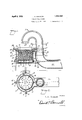
- housingor casing 10 which is supported by rods 11 extending vertically through lugs 12 on the outside of the casing, said rods being adjustably secured in said lugs by set-screws 1B.
- Two of the rods 11 are arranged at opposite sides of the casing, and oneof them is disposed Vat the rearward end, said rods forming adjustable legs ⁇ by means of which the casing may ⁇ belevelled regardless of irregularities in the level of the floor or other surface upon which it is placed.
- a retort l5, for a filler or Wick ⁇ 16, is set in the rcasing and centered therein by :lugs ⁇ 17 having shoulders 18 that slightly raise the bottom of theretort from the bottom of the casing, thus providing an air-space between the walls and bottom of the retort andthe oorresponding parts of the casing.
- the filler or wich 16 comprises granular. fragments of refractory mineral composition, ofporous or spongy consistency, and having relatively low heat conductivity. Disposed in the lower part of the retort isa.
- ⁇ perforatedcircular disk 19 havingtdownwardly extending lugs 2O which rest upon the bottom ⁇ of the retort, whereby to provide a distributing chamber-from which the filler materialis excluded, and to which the liquid fuel is supplied through a suitable pipe 21.
- the disk fits loosely Within theretort so that the fuel from the distributing chamber may flow about the edges thereof .as well as through theperforations therein, and. rise into the filler to a ⁇ level determined by the fuel control devices associated with the burner.
- An air conduit 22 is formedintegrally with the casing 10,the outwardly extending portion thereof being horizontahland the'innerend being turned upwardly and terminating in a substantially vertical portion 23 at the front side of the casing.
- the casing is disposed centrally in the lower. portion ⁇ ofthe combustion chamber 14 ⁇ ofthe furnace.
- the horizontal portion of the conduit .22 extends through the lower door-openingof the furnace-body and said openingis closedl about the conduit by means ⁇ of brickm or other suitable material which may be cemented to substantially seal the openingtand prevent the admission of air to the combustion chamber except through the conduit, to the outer end of which a suitable blower 33 may be connected to provide forced draft.
- a suitable blower 33 may be connected to provide forced draft.
- an inverted U-shaped air-flue 24 Inserted removably in the upper end of the vertical conduit portion 23 is an inverted U-shaped air-flue 24 having a flange 25, which rests upon the upper end of the conduit 22.
- the latter is notched atits inner side to receive a lug 26 ⁇ on the lower side of the flange 25, whereby the flue is prevented from swinging about the axis ofthe conduit, and the downwardly directed delivery end of the flue is kept centered above the retort.
- Said delivery end of the air-flue has a contracted orifice 27 for increasing the velocity of the air delivered to the retort when the burner is to be operated under lowdraft conditions such that increased velocity of the air-stream at the delivery Samuel becomes desirable.
- extension ring 28 Removably seated upon the upper edge of the casing l0 is an' extension ring 28, which has a downwardly extending flange 29 fitting inside the casing wall, and-at one side said ring has a concave or re-entrant portion 30 litt-ing about the airflue and over the flange 25, as shown.
- the inner side of the extension-ring 28, at its lower edge, is substantially in register with the inner side of the retort wall, and therefrom said inner side of the ring is inclined outwardly.
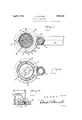
- the extension ring closes the upper end of the annular air-chamber 36 formed between the retort and casing, and the lower part of the ring is recessed to form a plurality of vents 31 which lead from the air-chamber upwardly and over the wall of the retort thus providing outlets from the air-chamber.
- Air is admitted to the chamber 36 in limited amounts through an aperture 32 in the common wall of the air conduit 22 and the casing 10.
- the aperture 32 also provides an opening through which the fuel supply pipe 2l extends into the conduit, said pipe passing through the conduit to a point outside of the furnace, thence extending laterally through the wall of the conduit to a control-valve 34E to which fuel is supplied from a suitable source.
- the gravitational level of the liquid fuel in the retort varies according to the rate at which the fuel is supplied thereto, and some of the liquid is carried above thegravitational level, or to the upper portion of the wick material, by the capillary action of said material, due to the porosity thereof above mentioned.
- the upper portions of the wick material quickly become heated to a temperature such as to cause vaporization of the liquid as it approaches the upper surface, and the resulting gas or vapor rising from the wick becomes mixed with the air emerging from the orifice of the air-flue.
- the flame at one side of the retort will strike and heat the ascending portion of the air-flue, so that the incoming air willbe slightly preheated.
- the air circulating in the conduit and air-space and through the vents, being cold, will cool the overflowing fuel which flows counter to the direction of the air and will lower its temperature below its vaporization temperature thereby preventing it from igniting in the casing or in the conduit.
Landscapes
- Engineering & Computer Science (AREA)
- Chemical & Material Sciences (AREA)
- Combustion & Propulsion (AREA)
- Mechanical Engineering (AREA)
- General Engineering & Computer Science (AREA)
- Evaporation-Type Combustion Burners (AREA)
Description
y 5, 1932. L I A* COCKLIN 1,852,292
LIQUID FUEL BURNER Fil-ed April 25, 1950 2 Sheets-Sheet l )5 INVENTOR L. A. CocKLrN.
ATTORNEY,
April 5, 1932.. v AI CQCKLJN 1,852,292*
LIQUID FUEL BURNER Filed April 25, 19,50 2 Sheets-Sheet 2 INVENTOR L. A. COCKLIN.
ATTORNEY `ai) a l substantially Patented Apr. 5, 1932 UNITED STATES LEWIS A. COUKLINyOF GRISWOLD, IOWA LIQUID FUEL BURNER i Application filed April 25,
`My invent-ion relates to oil or liquid fuel burners of the type wherein the liquid `fuel is delivered to a porous filler or wick contained within an open-topped retort, the combustion of the fuel occurring at the top of said retort, and the heat from the `zone of combustion serving to vaporize the liquid fuel in the upper portions of the filler or wick. It is the object of my invention to im provide a burner of this character of simple,
durable and inexpensive construction wherein liquid fuel is supplied to the lower portion of the retort and a current of air is directed impingingly upon the surface ofthe filler. A further object of my invention is `to provide in a burner of this class means for encasing or jacketing the body of the retort to shield the same from the heat within the combustion chamber in which the burner is disposed when in use, whereby to limit the transmission of heat from the zone of combustion to the fuel in the lower portion of the retort. A further object is to provide means for causing a limited circulation of cold air through the inclosed jacket-space about the retort and to provide means whereby any excess ofthe liquid fuel which may be supplied to the retort, so as to overflow therefrom, will be received into said jacket- Space and conducted therefrom through the cold-air supply conduit to a point outside the combustion chamber.
Iattain these objects by the device illustrated in the accompanying drawings in which:
Fig. 1 is a, vertical longitudinal section through the burner.
Fig. 2 is a horizontal section on line 2-2 of Fig. 1.
Fig. 3 is a horizontal sectional view taken on line 3-3 of Fig. 1.
Fig. d is a horizontal section on line 4-4 of Fig. 1, the view being upward from the plane of section.
Fig. 5 is a diagrammatic vertical section through a furnace i with the oil burner installed therein.
In carrying out my invention according to the illustrated embodiment thereof I provide cylindrical open-topped 1930. Serial `N0.\447,1156.
In the operation of the burner, the gravitational level of the liquid fuel in the retort varies according to the rate at which the fuel is supplied thereto, and some of the liquid is carried above thegravitational level, or to the upper portion of the wick material, by the capillary action of said material, due to the porosity thereof above mentioned. After operation of the burner has been started by igniting the fuel at the top of the'retort, the upper portions of the wick material quickly become heated to a temperature such as to cause vaporization of the liquid as it approaches the upper surface, and the resulting gas or vapor rising from the wick becomes mixed with the air emerging from the orifice of the air-flue. The impinging air-current, sweepin g across the upper surface of the filler or wick material, carries the flame radially outward and at the outer edge of the retort the fla-me is directed upwardly by the extension ring 28. By reason of the radial spreading of the flamel outwardly from the central portion of the filler surface, the flame at one side of the retort will strike and heat the ascending portion of the air-flue, so that the incoming air willbe slightly preheated. The
By reason ofthe low conductivity ofthe porous granular wick material, the heat from the upper portion or vaporization zone thereof is transmitted very slowlyto the lower portion of the retort, and cooling of the latter is effected continuously by circulation of air through the chamber 36 about the retort. Said air-circulation through the chamber 36 is caused by air from the conduit 22 entering the chamber 'through the aperture 32 and emerging from the vents 3l above the upper edge of the retort-wall, at which points there is thus provided an auxiliary air-supply for supporting combustion of the fuel.
Should the flame of the burner become extinguished while the liquid fuel is being supplied to the retort, or should the fuel supply be turned on without igniting the burner, or if an excessive quantity of fuel be supplied to the retort at any time, so that the liquid level in the retort would riseto the top thereof, the excess liquid may flow over the upper edge of the retort through the, vents 31 into the casing. Thence it will pass into the conduit through the aperture 32 and flow along said conduit to a point 'outside of the furnace, where it may be received by suitable well known means. The air circulating in the conduit and air-space and through the vents, being cold, will cool the overflowing fuel which flows counter to the direction of the air and will lower its temperature below its vaporization temperature thereby preventing it from igniting in the casing or in the conduit.
I-Iaving thus described my invention what I claim is:
In a liquid fuel burner, a casing open at the top, an open-topped retort of substantially the saine height as the casing and having its walls spaced therefrom within the casing to provide an air-space between them, means for supplying liquid fuel to the lower portion of the retort, a Wick of refractory porous granular material disposed in the retort and substantially iilling the same, an air-iue having a delivery orifice positioned centrally above the retort and adapted to direct air onto the surface of the wick material therein, an extension-ring seated upon the upper edges of the retort and casingr to close the upper end of the air-space, said ring having vents extendl ing from the airspace about the upper edge of the retort and directed inwardly over the wiel; therein, an airconduit connected with said air-flue for delivering air thereto, said conduit extending horizontally at a levely below the bottom of the casing, and there being a limited opening connecting said conduit with the lowest portion of the air-space about the retort, whereby air from said conduit may pass through said airspace to said vents, and 2o liquid fuel overflowing the wall of the retort will be conducted through said vents and airspace to the bottom of the casing and thence through said opening to the horizontal air-- conduit.
a5 LEWIS A. COCKLIN.
Priority Applications (1)
| Application Number | Priority Date | Filing Date | Title |
|---|---|---|---|
| US447156A US1852292A (en) | 1930-04-25 | 1930-04-25 | Liquid fuel burner |
Applications Claiming Priority (1)
| Application Number | Priority Date | Filing Date | Title |
|---|---|---|---|
| US447156A US1852292A (en) | 1930-04-25 | 1930-04-25 | Liquid fuel burner |
Publications (1)
| Publication Number | Publication Date |
|---|---|
| US1852292A true US1852292A (en) | 1932-04-05 |
Family
ID=23775218
Family Applications (1)
| Application Number | Title | Priority Date | Filing Date |
|---|---|---|---|
| US447156A Expired - Lifetime US1852292A (en) | 1930-04-25 | 1930-04-25 | Liquid fuel burner |
Country Status (1)
| Country | Link |
|---|---|
| US (1) | US1852292A (en) |
-
1930
- 1930-04-25 US US447156A patent/US1852292A/en not_active Expired - Lifetime
Similar Documents
| Publication | Publication Date | Title |
|---|---|---|
| US2091658A (en) | Oil burner | |
| US2355416A (en) | Oil pilot with supplemental air supply | |
| US2218154A (en) | Portable fuel oil burner | |
| US1852292A (en) | Liquid fuel burner | |
| US2533092A (en) | Tobacco curing apparatus | |
| US1933044A (en) | Apparatus for burning o | |
| US2432143A (en) | Liquid fuel feeding and burning apparatus | |
| US2136317A (en) | Oil burning furnace | |
| US892706A (en) | Hydrocarbon-burner. | |
| US1881687A (en) | Oil burner | |
| US1639518A (en) | Burner | |
| US1214547A (en) | Oil-stove. | |
| US1618392A (en) | Oil burner | |
| US2396675A (en) | Liquid fuel burner | |
| US1495929A (en) | Burner | |
| US1871952A (en) | Oil burning apparatus | |
| US1570003A (en) | Oil burner | |
| US1697687A (en) | Oil-burning heater | |
| US2180444A (en) | Combustion apparatus | |
| US1685804A (en) | Liquid-fuel burner | |
| US1441008A (en) | Liquid-fuel burner | |
| US2094274A (en) | Oil burning furnace | |
| US1852290A (en) | Liquid fuel burner | |
| US1484814A (en) | Oil awd gas burner | |
| USRE16954E (en) | cocklin |