US1852262A - Fixture support - Google Patents
Fixture support Download PDFInfo
- Publication number
- US1852262A US1852262A US450002A US45000230A US1852262A US 1852262 A US1852262 A US 1852262A US 450002 A US450002 A US 450002A US 45000230 A US45000230 A US 45000230A US 1852262 A US1852262 A US 1852262A
- Authority
- US
- United States
- Prior art keywords
- head
- supporting
- ears
- arm
- fixture
- Prior art date
- Legal status (The legal status is an assumption and is not a legal conclusion. Google has not performed a legal analysis and makes no representation as to the accuracy of the status listed.)
- Expired - Lifetime
Links
- 239000002184 metal Substances 0.000 description 15
- 210000005069 ears Anatomy 0.000 description 13
- 210000002105 tongue Anatomy 0.000 description 5
- 238000010276 construction Methods 0.000 description 3
- 241000237503 Pectinidae Species 0.000 description 2
- 230000006978 adaptation Effects 0.000 description 2
- 235000020637 scallop Nutrition 0.000 description 2
- 239000011521 glass Substances 0.000 description 1
- 238000004519 manufacturing process Methods 0.000 description 1
- 238000012986 modification Methods 0.000 description 1
- 230000004048 modification Effects 0.000 description 1
- 239000000344 soap Substances 0.000 description 1
- 238000005476 soldering Methods 0.000 description 1
- 238000003466 welding Methods 0.000 description 1
Images
Classifications
-
- A—HUMAN NECESSITIES
- A47—FURNITURE; DOMESTIC ARTICLES OR APPLIANCES; COFFEE MILLS; SPICE MILLS; SUCTION CLEANERS IN GENERAL
- A47G—HOUSEHOLD OR TABLE EQUIPMENT
- A47G29/00—Supports, holders, or containers for household use, not provided for in groups A47G1/00-A47G27/00 or A47G33/00
- A47G29/08—Holders for articles of personal use in general, e.g. brushes
Definitions
- This invention relates to a fixture support. It a primary object and purpose oi the present invention to provide a simple and very economically produced supporting arm or bracket from sheet metal, which may be utilized for supporting a great many auxiliary devices whereby, by use of either one or a number of the supporting fixtures of the invention, many articles of sale may be made, all having as a foundation the supporting [ixture or arm of my present invention.
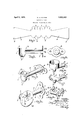
- Fig. 1 is a view of the sheet metal blank from which the main element of the support is made.
- Fig. 2 is an elevation of the base, also of sheet metal, to which the part made from the blank shown in Fig. l. is permanently secured.
- Fig. 3 is a longitudinal vertical section of the completely fabricated and assembled iiX- ture support.
- Fig. i is a perspective view thereof.
- Fig. 5 is a similar perspective view in which the support has modifications in certain particulars for carrying rods or roll holding cores between two of said supports.
- Figs. 6 and '7 show the support illustrated in Fig. %l utilized to carry dillere-nt types oi articles, that in Fig. 6 a metal cup, and that in Fig. T a flat plate with tooth brush receiving notches at its edges, and
- Fig. 8 is a perspective view showing two of the supports utilized to carry a rod between them.
- the blank of flat metal from which the major portion of the fixture support is made comprises, as shown in Fig. 1, a central body 1 at the lower edge of which are a plurality of scalloped portions extending ClOWll'Wtilih ly, and at the upper edge of which are a plurality of ears 3 spaced from each other and preferably of substantially circular outline.
- sections 4 extend outwardly away from each other and preferably the same widen progressively outward as shown.
- Each of the sections 4 terminates at its end in a short and wide tongue 5, the width of which is slightly less than the width of the outer end of each section 4 t iereby providing the shoulders shown between the tongues 5 and said sections 4 at their unctures.
- the blank described is bent and pressed into shape, the central body 1 being formed substantially into a vertical cylinder open at its upper end from which the ears 3 are turned horizontally outwardly at right angles, While the depending scalloped extensions 2 are bent and curved inwardly toward each other to bring their edges into substantial contact, making a rounded closed end to the body 1 as best shown in Fig. 4:.
- the sections t are each pressed into half: round form so that when brought together their longitudinal edges are in contact engagement thereby making a horizontally tapered arm circular cross section.
- a base 6 formed from flat metal isprovided, which at its central portion, has an outwardly embossed section 7 with acircular opening therethrough.
- the tongues 5, which likewise have been formed into semi-circular shape, when brought together are inserted through the opening in the embossed portion 7 of the base, the inner parts of the.
- the supporting fixture which has been made in this manner from two pieces of flat metal, one of which comprises thebase 6, is shown in Fig. l and to the upper end of the outer cylindrical head, various articles of sheet metal'may be attac-hedby welding, soldering, riveting or otherwise permanently securing the same to the horizontally located ears 3.
- a metal cup 8 is shown at attached to said cars which may be utilized as a soap dish, to hold a glass or may be used for any other purpose for which it is adapted; while in Fig. 7 a flat metal plate 9 of semi-circular form is secured to the ears 3 and at its edges has a plurality of notches in which the handles of tooth brushes or other articles suitable to be entered in the slots may be received and held.
- a supporting fixture has ears of the shape indicated at 10, cut in the upper edge of the blank similar to the ears 3 as shown in Fig. 1 while a rather deep notch indicated at 11 is cut downwardly in the body 1.
- the supporting fixture when shaped and formed and attached to the base 6, has the upper end of the head at 1 closed by a plate 12 with openings to receive the ears 10, which are headed over at their ends, to make a secure connection.
- a slot 13 is cut inwardly from one edge of the plate 12 whereby, when the plate is in operative assembled position, as shown in Fig. 5, the slots 13 and 11 join and lie at right angles to each other.
- a horizontal rod 14 may be located between two of the supporting fixtures, as in Fig. 8, and in this manner a rod for holding rolls of paper is conveniently and easily supported.
- towel rods may be supported between two of the supporting fixtures properly spaced apart, the ends of the core being received in the slots 13 and 11.
- An article of the class described comprising avertically positioned cylindrical head open at its upper and closed at its bottom, and a substantially horizontal arm extending from one side of said head, said head and arm being formed from a single blank of sheet metal comprising, a central flat body adapted to be formed into a cylinder and having spaced apart scalloped portions at one edge adapted to be turned toward each other to close the end of the cylinder, and integral sections of flat metal extending outwardly one from each end of the body adapted to be pressed longitudinally into substantially half round shape andbrought together to make said arm.
- a supporting member made from a single piece of fiat metal comprising, a central body having spaced apart downwardly extending scalloped portions each comprising substantially a segment of a spherical surface, and outwardly extending sections one at each end of said body whereby said sections may be formed longitudinally into substantially half round shape and said body may be formed into cylindrical form with said seallops curved and bent inwardly toward each other to close an end of the cylinder, said sections being brought together to form a substantially horizontal supporting arm having circular cross section.
- a supporting member of the class described comprising, a head in the shape substantially of a vertical cylinder open at one end, integral means on the head, said integral means including several scallops of spherical shape, said scallops abutting together to close the other end thereof, and an integral arm extending laterally from the head, all made from a single blank of flat metal.
- a supporting member of the class described comprising, a head in the shape substantially of a vertical cylinder open. at one end, integral means on the head closing the other end thereof, ears extending from the open end and around the edges of said head, an integral arm extending laterally from the head, all made from a single blank of fiat metal, and an article located adjacent and secured to said ears.
- a supporting member comprising, a head in the shape substantially of a vertical cylinder, ears extending from one end of the head and located around the edges thereof, said ears being adapted to lie against the said flat surface of the particular device supported thereby and an arm extending laterally from said iead, said arms being rigidly attached to the said head for the purpose described.
Landscapes
- Forms Removed On Construction Sites Or Auxiliary Members Thereof (AREA)
Description
April 1932 w. H PLEISS 1,852,262
FIXTURE SUPPORT Original Filed May 5. 1930 Patented Apr. 5, 1932 UNITED STATES PATENT OFFICE WALTER H. PLEXSS, OF LUDING-TON, MICHIGAN, ASSIGNOR TO HANDY THINGS MANU- FACTURING COMPANY, OF LUDINGTJUN, MICHIGAN, A CORPORATION OF MICHIGAN FIXTURE SUPPORT Application filed May 5, 1930, Serial No. 450,002. Renewed July 18, 1931.
This invention relates to a fixture support. It a primary object and purpose oi the present invention to provide a simple and very economically produced supporting arm or bracket from sheet metal, which may be utilized for supporting a great many auxiliary devices whereby, by use of either one or a number of the supporting fixtures of the invention, many articles of sale may be made, all having as a foundation the supporting [ixture or arm of my present invention.
l'in understanding of the invention for the attainment of the ends stated as well as many others not at this time specifically enumerated may be had from the following description, taken in connection with the accompanying drawings, in which,
Fig. 1 is a view of the sheet metal blank from which the main element of the support is made.
Fig. 2 is an elevation of the base, also of sheet metal, to which the part made from the blank shown in Fig. l. is permanently secured.
Fig. 3 is a longitudinal vertical section of the completely fabricated and assembled iiX- ture support.
Fig. i is a perspective view thereof.
Fig. 5 is a similar perspective view in which the support has modifications in certain particulars for carrying rods or roll holding cores between two of said supports.
Figs. 6 and '7 show the support illustrated in Fig. %l utilized to carry dillere-nt types oi articles, that in Fig. 6 a metal cup, and that in Fig. T a flat plate with tooth brush receiving notches at its edges, and
Fig. 8 is a perspective view showing two of the supports utilized to carry a rod between them.
Like reference characters refer to like parts in the different figures of the drawings.
The blank of flat metal from which the major portion of the fixture support is made, comprises, as shown in Fig. 1, a central body 1 at the lower edge of which are a plurality of scalloped portions extending ClOWll'Wtilih ly, and at the upper edge of which are a plurality of ears 3 spaced from each other and preferably of substantially circular outline.
From each end of the body 1 sections 4 extend outwardly away from each other and preferably the same widen progressively outward as shown. Each of the sections 4: terminates at its end in a short and wide tongue 5, the width of which is slightly less than the width of the outer end of each section 4 t iereby providing the shoulders shown between the tongues 5 and said sections 4 at their unctures.
The blank described is bent and pressed into shape, the central body 1 being formed substantially into a vertical cylinder open at its upper end from which the ears 3 are turned horizontally outwardly at right angles, While the depending scalloped extensions 2 are bent and curved inwardly toward each other to bring their edges into substantial contact, making a rounded closed end to the body 1 as best shown in Fig. 4:. The sections t are each pressed into half: round form so that when brought together their longitudinal edges are in contact engagement thereby making a horizontally tapered arm circular cross section.
A base 6 formed from flat metal isprovided, which at its central portion, has an outwardly embossed section 7 with acircular opening therethrough. The tongues 5, which likewise have been formed into semi-circular shape, when brought together are inserted through the opening in the embossed portion 7 of the base, the inner parts of the.
tongues indicated at 5a in Fig. 3 bearing against the sides ofthe opening while the edge portions thereof are pressed outwardly to make flanges 5b. Said flanges together with the shoulders between the tongues 5 and the ends of the arm sections a make a very secure and permanent connection of the base to the arm of the fixture.
The supporting fixture, which has been made in this manner from two pieces of flat metal, one of which comprises thebase 6, is shown in Fig. l and to the upper end of the outer cylindrical head, various articles of sheet metal'may be attac-hedby welding, soldering, riveting or otherwise permanently securing the same to the horizontally located ears 3. For instance, in Fig. 6 a metal cup 8 is shown at attached to said cars which may be utilized as a soap dish, to hold a glass or may be used for any other purpose for which it is adapted; while in Fig. 7 a flat metal plate 9 of semi-circular form is secured to the ears 3 and at its edges has a plurality of notches in which the handles of tooth brushes or other articles suitable to be entered in the slots may be received and held.
The supporting fixture is adapted for a great many other uses some of which are illustrated. In Fig. 5 a supporting fixture has ears of the shape indicated at 10, cut in the upper edge of the blank similar to the ears 3 as shown in Fig. 1 while a rather deep notch indicated at 11 is cut downwardly in the body 1. The supporting fixture, when shaped and formed and attached to the base 6, has the upper end of the head at 1 closed by a plate 12 with openings to receive the ears 10, which are headed over at their ends, to make a secure connection. A slot 13 is cut inwardly from one edge of the plate 12 whereby, when the plate is in operative assembled position, as shown in Fig. 5, the slots 13 and 11 join and lie at right angles to each other.
With such a construction a horizontal rod 14 may be located between two of the supporting fixtures, as in Fig. 8, and in this manner a rod for holding rolls of paper is conveniently and easily supported. Likewise towel rods may be supported between two of the supporting fixtures properly spaced apart, the ends of the core being received in the slots 13 and 11.
There are a great many other adaptations and uses of the supporting fixture which I have devised but it is not necessary for further disclosure in the description of the present invention. It is evident that the support described is one which can'be made very readily and very cheaply and that it has a wide adaptation and use. The invention is defined in the appended claims and is to be considered comprehensive of all forms of structure coming within their scope.
I claim:
1. An article of the class described comprising avertically positioned cylindrical head open at its upper and closed at its bottom, and a substantially horizontal arm extending from one side of said head, said head and arm being formed from a single blank of sheet metal comprising, a central flat body adapted to be formed into a cylinder and having spaced apart scalloped portions at one edge adapted to be turned toward each other to close the end of the cylinder, and integral sections of flat metal extending outwardly one from each end of the body adapted to be pressed longitudinally into substantially half round shape andbrought together to make said arm.
2. A construction containing-the elements incombination defined'in cla-iml, said head at the open end thereof. having a plurality of 7 integral ears extending horizontally outward from and in spaced apart relation around said head.
3. A supporting member made from a single piece of fiat metal comprising, a central body having spaced apart downwardly extending scalloped portions each comprising substantially a segment of a spherical surface, and outwardly extending sections one at each end of said body whereby said sections may be formed longitudinally into substantially half round shape and said body may be formed into cylindrical form with said seallops curved and bent inwardly toward each other to close an end of the cylinder, said sections being brought together to form a substantially horizontal supporting arm having circular cross section.
4. A supporting member of the class described, comprising, a head in the shape substantially of a vertical cylinder open at one end, integral means on the head, said integral means including several scallops of spherical shape, said scallops abutting together to close the other end thereof, and an integral arm extending laterally from the head, all made from a single blank of flat metal.
5. A construction containing the elements in combination defined in claim 1, combined with ears turned outwardly at the open end and around the edges of said head adapted to serve as connecting means between said head and an article located adjacent and secured thereto.
6. A supporting member of the class described, comprising, a head in the shape substantially of a vertical cylinder open. at one end, integral means on the head closing the other end thereof, ears extending from the open end and around the edges of said head, an integral arm extending laterally from the head, all made from a single blank of fiat metal, and an article located adjacent and secured to said ears.
7. In a device of the character described adapted to be utilized as a supporting means for a number of devices, each having a fiat supporting surface, the combination of, a supporting member comprising, a head in the shape substantially of a vertical cylinder, ears extending from one end of the head and located around the edges thereof, said ears being adapted to lie against the said flat surface of the particular device supported thereby and an arm extending laterally from said iead, said arms being rigidly attached to the said head for the purpose described.
In testimony whereof I aiiix my signature.
- WALTER H. PLEISS.
Priority Applications (1)
| Application Number | Priority Date | Filing Date | Title |
|---|---|---|---|
| US450002A US1852262A (en) | 1930-05-05 | 1930-05-05 | Fixture support |
Applications Claiming Priority (1)
| Application Number | Priority Date | Filing Date | Title |
|---|---|---|---|
| US450002A US1852262A (en) | 1930-05-05 | 1930-05-05 | Fixture support |
Publications (1)
| Publication Number | Publication Date |
|---|---|
| US1852262A true US1852262A (en) | 1932-04-05 |
Family
ID=23786356
Family Applications (1)
| Application Number | Title | Priority Date | Filing Date |
|---|---|---|---|
| US450002A Expired - Lifetime US1852262A (en) | 1930-05-05 | 1930-05-05 | Fixture support |
Country Status (1)
| Country | Link |
|---|---|
| US (1) | US1852262A (en) |
Cited By (4)
| Publication number | Priority date | Publication date | Assignee | Title |
|---|---|---|---|---|
| US2689582A (en) * | 1950-02-01 | 1954-09-21 | Albert L Coulter | Manual adapter for automatic chokes |
| US3149811A (en) * | 1962-09-17 | 1964-09-22 | Ajax Hardware Mfg Corp | Mounting bracket for elongated track |
| US5664751A (en) * | 1996-08-12 | 1997-09-09 | Lan; Chun-Min | Article holder |
| US20220248875A1 (en) * | 2021-02-05 | 2022-08-11 | Westrock Shared Services, Llc | Cellulosic display structures and associated cellulosic display systems |
-
1930
- 1930-05-05 US US450002A patent/US1852262A/en not_active Expired - Lifetime
Cited By (5)
| Publication number | Priority date | Publication date | Assignee | Title |
|---|---|---|---|---|
| US2689582A (en) * | 1950-02-01 | 1954-09-21 | Albert L Coulter | Manual adapter for automatic chokes |
| US3149811A (en) * | 1962-09-17 | 1964-09-22 | Ajax Hardware Mfg Corp | Mounting bracket for elongated track |
| US5664751A (en) * | 1996-08-12 | 1997-09-09 | Lan; Chun-Min | Article holder |
| US20220248875A1 (en) * | 2021-02-05 | 2022-08-11 | Westrock Shared Services, Llc | Cellulosic display structures and associated cellulosic display systems |
| US11839316B2 (en) * | 2021-02-05 | 2023-12-12 | Westrock Shared Services, Llc | Cellulosic display structures and associated cellulosic display systems |
Similar Documents
| Publication | Publication Date | Title |
|---|---|---|
| US1957353A (en) | Attachment for faucets | |
| US1887894A (en) | Sign holder | |
| US1852262A (en) | Fixture support | |
| US2310842A (en) | Tieback holder | |
| US2209318A (en) | Clip | |
| US2739840A (en) | Toilet paper holder | |
| US1914006A (en) | Folding furniture | |
| US2104139A (en) | Candle holder | |
| US1305777A (en) | Kitcheh ahd table article | |
| US2563704A (en) | Garment hanger | |
| US1805742A (en) | Rod supporting bracket | |
| US2311495A (en) | Tree bracket | |
| US1912704A (en) | Perch holder | |
| US1841028A (en) | Christmas tree ornament support | |
| US2024294A (en) | Detachable handle | |
| US3527358A (en) | Garment hanger attachment | |
| US2107003A (en) | Garment protector for garment hangers | |
| US2062566A (en) | Garment hanger guard | |
| US2034859A (en) | Garment hanger | |
| US1364190A (en) | Towel-holder | |
| US1799319A (en) | Combined bracket and towel-bar fixture | |
| US2111314A (en) | Top lift attachment | |
| US1362023A (en) | Egg-holder | |
| US1717556A (en) | Spoon and fork holder | |
| US1679183A (en) | Book carrier |