US1852223A - Strop - Google Patents
Strop Download PDFInfo
- Publication number
- US1852223A US1852223A US434502A US43450230A US1852223A US 1852223 A US1852223 A US 1852223A US 434502 A US434502 A US 434502A US 43450230 A US43450230 A US 43450230A US 1852223 A US1852223 A US 1852223A
- Authority
- US
- United States
- Prior art keywords
- strop
- stropping
- stroke
- razor
- blade
- Prior art date
- Legal status (The legal status is an assumption and is not a legal conclusion. Google has not performed a legal analysis and makes no representation as to the accuracy of the status listed.)
- Expired - Lifetime
Links
- 239000010985 leather Substances 0.000 description 3
- 238000010008 shearing Methods 0.000 description 2
- 238000000034 method Methods 0.000 description 1
Images
Classifications
-
- B—PERFORMING OPERATIONS; TRANSPORTING
- B24—GRINDING; POLISHING
- B24D—TOOLS FOR GRINDING, BUFFING OR SHARPENING
- B24D15/00—Hand tools or other devices for non-rotary grinding, polishing, or stropping
- B24D15/06—Hand tools or other devices for non-rotary grinding, polishing, or stropping specially designed for sharpening cutting edges
- B24D15/08—Hand tools or other devices for non-rotary grinding, polishing, or stropping specially designed for sharpening cutting edges of knives; of razors
- B24D15/088—Hand tools or other devices for non-rotary grinding, polishing, or stropping specially designed for sharpening cutting edges of knives; of razors with whetting leather
Definitions
- My present invention relates to improvements in strops for dressing the edges of fine cutting instruments such as razors.
- fine cutting instruments such as razors.
- the cutting edges of fine and delicate cutting instruments were minutely serrated, and barbers have generally conformedv to this knowledge or theory of the presence of the serrations on the cutting edge by hold- 1@ ing the razor at an angle with the strop while stropping, because in shavingl with an old fashioned or ordinary razor, the blade is usually held at an angle with the stroke so as to secure a shearing. It is thought, and
- safety razor came into generaly use a diversity of opinion arose as to the proper method of stropping the blades, because, with safety razors the blade is, more generally, held at rightV angles with the direction of the stroke when shaving.
- One theory with respect to the stropping ⁇ of safety razors is that as the razor is held at right angles to the stroke in shaving the blade should likewise be held at right angles to the stroke in stropping, and the other theory is that inclining the minute serrations upon the cutting edge more or less-obliquely to the cutting edge is of as much advantage in stropping a safety razor as in stropping an ordinary razor.
- My present invention has for its object the provision of simple means ina strop for razors and other line edged tools for dependably securing a right angled disposition of the serrations upon the cutting edge in a strop which will be sufciently yielding to conform to the cutting edge of the blade while stropping.
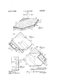
- Fig. l is a perspective of a strop embody f ing my invention
- Fig. 2 is a plan of the structure shown in Fig. l showing the disposition Vof the razor in full and dotted lines at the commencement and end ⁇ of a stropping stroke from left to rioht
- i t"Fig 3 is a view similarto Fig. 2in which the razorv is shown Vin full and dotted lines at the beginning andend of a stropping stroke from right to left; and, "1
- Fig. 4 is a plan of a blade showing the 65 ⁇ angle of the stroke from left to'rglit to the Y cutting edge by means of arrows in full lines and the angle of'the'strokeV fromright to left to the cutting edge by means of arrows in dotted lines.
- My strop consists of a piece of pig skin,or other suitable leather, preparedand dressed in accordance with the usual practice in order to condition it for performing thel functionsofa strop.
- This piecerof leather, or strop, 5 is longitudinally extended', that is provided with opposite parallel longitudinal edges 6 and 7 terminating at its respective 80 ends in converging edges 8 and 9, which are at right angles to each other.
- the cutting edge 10a of the razor blade 10 is placed parallel with the adj acent end edge 8 of thel strop and at right 9C' angles to the adjacent end edge 9.
- the blade is then moved from leftto right parallel with the edges 6 and 7, as shown by the arrows in Fig. 2, until it reaches the position shown in dotted lines in Fig. 2.
- Theblade and handle are then rolled overwith the handle as a back until the blade assumes the position shown in full lines in Fig. 3.
- the blade is then moved from right ⁇ to left parallel withthe edges 6 and 7 as shown by the dotted lines IDF yin Fig. 3.
- the holder is then rotated on its back, which brings the razor in the position shown in full lines in Fig. 2 for another stroke from left to right.
- Fig. 4 the angle of stroke, when stropping as above described, to the cutting edge in a left to right stroke is shown by the arrows l2 in full lines and the angle of the stroke from right to left is shown by the arrows 13 in dotted lines, and as will be seen, these strokes are at substantial right angles and n will be found to produce most dependab-ly and uniformly the requisite cutting edges of greatest sharpness.
- strops are generally held in amore or less swinging condition and also sometimes padded so as to securek the most intimate yieldingV contact between the strop and blade during stropping.
- the base 14 I provide in the form of a square, as shown in Figs. 2 and 8, with one corner thereof truncated along a longitudinal edge of the strop 5 and having ⁇ the opposite right angle corners of the base conforming with the right angle end edges 8 and 9 of the strop.
- Such a strop may be vconveniently placed ⁇ upon any suitable supporting surface or held in the hand while stropping.
- a strop for dressing the edges of cutting instruments having Vparallel longitudinal edgesfor guiding the movement of the instrument upon the strop and ends the edges whereof converge at rightangles lfor indicating the relationrof the cutting edge to the direction of movement during stropping.
- a strop'for dressing the edges of cutting instruments comprising a base of sponge or gassed rubber, the plan whereof is square with a truncated corner and a leather mounted Y upon said base having parallel edgesone whereof coincides Ywith the truncated corner of said base and the ends whereof coincide with opposite corners of said base.
Landscapes
- Engineering & Computer Science (AREA)
- Mechanical Engineering (AREA)
- Treatment Of Fiber Materials (AREA)
Description
April 5, E. G. sTocKERT STROP Filed March 1o.
Patented YApr. 5, 1932 EDWARD Gr. STOCKERT,
or CHICAGO, rnriritois STROII? l Application flied March 1o, 1930. semina. 434,502.
My present invention relates to improvements in strops for dressing the edges of fine cutting instruments such as razors. been generally known for a very long time 5 that the cutting edges of fine and delicate cutting instruments were minutely serrated, and barbers have generally conformedv to this knowledge or theory of the presence of the serrations on the cutting edge by hold- 1@ ing the razor at an angle with the strop while stropping, because in shavingl with an old fashioned or ordinary razor, the blade is usually held at an angle with the stroke so as to secure a shearing. It is thought, and
generally believed, that the shearing action of an ordinary razor is somewhat improved by stropping the razor at an angle with the strop.
I/Vhen the so-called, safety razor came into generaly use a diversity of opinion arose as to the proper method of stropping the blades, because, with safety razors the blade is, more generally, held at rightV angles with the direction of the stroke when shaving. One theory with respect to the stropping` of safety razors is that as the razor is held at right angles to the stroke in shaving the blade should likewise be held at right angles to the stroke in stropping, and the other theory is that inclining the minute serrations upon the cutting edge more or less-obliquely to the cutting edge is of as much advantage in stropping a safety razor as in stropping an ordinary razor.
I have found that for the best and most uniform and dependable results with both old fashioned or ordinary and safety razors the serrations upon the cutting edge influenced by stropping in one direction should be as nearly at right angles as possible with the serrations influenced by stropping the razor upon the other face.
My present invention has for its object the provision of simple means ina strop for razors and other line edged tools for dependably securing a right angled disposition of the serrations upon the cutting edge in a strop which will be sufciently yielding to conform to the cutting edge of the blade while stropping.
It hasv I have attained the foregoing objects `and results by means of the strop fillustrated' in the accompanying drawings, in .whichi Fig. l is a perspective of a strop embody f ing my invention; v 'p f 55 Fig. 2 is a plan of the structure shown in Fig. l showing the disposition Vof the razor in full and dotted lines at the commencement and end` of a stropping stroke from left to rioht; i t"Fig 3 is a view similarto Fig. 2in which the razorv is shown Vin full and dotted lines at the beginning andend of a stropping stroke from right to left; and, "1
Fig. 4; is a plan of a blade showing the 65` angle of the stroke from left to'rglit to the Y cutting edge by means of arrows in full lines and the angle of'the'strokeV fromright to left to the cutting edge by means of arrows in dotted lines. Y
Similar reference characters referto similar parts throughout the respective views.
My strop consists of a piece of pig skin,or other suitable leather, preparedand dressed in accordance with the usual practice in order to condition it for performing thel functionsofa strop. This piecerof leather, or strop, 5 is longitudinally extended', that is provided with opposite parallel longitudinal edges 6 and 7 terminating at its respective 80 ends in converging edges 8 and 9, which are at right angles to each other.
I have illustrated the operation of my strop in Figs. 2, 3. and 4 in connectionwith a safety razor blade 10,'shown in Figs. 2 and 3, assem 85 bled with a stropping holder ll.
In stropping, commencing with the stroke from left to riglit,the cutting edge 10a of the razor blade 10 is placed parallel with the adj acent end edge 8 of thel strop and at right 9C' angles to the adjacent end edge 9. The blade is then moved from leftto right parallel with the edges 6 and 7, as shown by the arrows in Fig. 2, until it reaches the position shown in dotted lines in Fig. 2. Theblade and handle are then rolled overwith the handle as a back until the blade assumes the position shown in full lines in Fig. 3. The blade is then moved from right `to left parallel withthe edges 6 and 7 as shown by the dotted lines IDF yin Fig. 3. At the end of. this stroke the holder is then rotated on its back, which brings the razor in the position shown in full lines in Fig. 2 for another stroke from left to right. y Y
In Fig. 4 the angle of stroke, when stropping as above described, to the cutting edge in a left to right stroke is shown by the arrows l2 in full lines and the angle of the stroke from right to left is shown by the arrows 13 in dotted lines, and as will be seen, these strokes are at substantial right angles and n will be found to produce most dependab-ly and uniformly the requisite cutting edges of greatest sharpness.
I am aware that strops are generally held in amore or less swinging condition and also sometimes padded so as to securek the most intimate yieldingV contact between the strop and blade during stropping. I have secured a similar, but I believe improved,lyielding action of the strop by mounting the same upon a base 14 of sponge or gassed rubber. The base 14 I provide in the form of a square, as shown in Figs. 2 and 8, with one corner thereof truncated along a longitudinal edge of the strop 5 and having `the opposite right angle corners of the base conforming with the right angle end edges 8 and 9 of the strop. Such a strop may be vconveniently placed `upon any suitable supporting surface or held in the hand while stropping. l
y From the foregoing description taken in connection With'the drawings it will be seen that I have provided extremely simple instrumentalities in a strop for securing a right angledrelation of the strokes in stropping edged tools. Y e
Having described my invention what I claim as new and desire to secure by Letters Patent is: Y
1. A strop for dressing the edges of cutting instruments having Vparallel longitudinal edgesfor guiding the movement of the instrument upon the strop and ends the edges whereof converge at rightangles lfor indicating the relationrof the cutting edge to the direction of movement during stropping.
2. A strop'for dressing the edges of cutting instruments comprising a base of sponge or gassed rubber, the plan whereof is square with a truncated corner and a leather mounted Y upon said base having parallel edgesone whereof coincides Ywith the truncated corner of said base and the ends whereof coincide with opposite corners of said base.
EDWARD G. sTocKERT.
Priority Applications (1)
| Application Number | Priority Date | Filing Date | Title |
|---|---|---|---|
| US434502A US1852223A (en) | 1930-03-10 | 1930-03-10 | Strop |
Applications Claiming Priority (1)
| Application Number | Priority Date | Filing Date | Title |
|---|---|---|---|
| US434502A US1852223A (en) | 1930-03-10 | 1930-03-10 | Strop |
Publications (1)
| Publication Number | Publication Date |
|---|---|
| US1852223A true US1852223A (en) | 1932-04-05 |
Family
ID=23724483
Family Applications (1)
| Application Number | Title | Priority Date | Filing Date |
|---|---|---|---|
| US434502A Expired - Lifetime US1852223A (en) | 1930-03-10 | 1930-03-10 | Strop |
Country Status (1)
| Country | Link |
|---|---|
| US (1) | US1852223A (en) |
Cited By (3)
| Publication number | Priority date | Publication date | Assignee | Title |
|---|---|---|---|---|
| US3229425A (en) * | 1964-10-13 | 1966-01-18 | Carborundum Co | Resilient-backed abrasive stone |
| DE102006001559A1 (en) * | 2006-01-12 | 2007-07-19 | Eduard Schiller | Re-sharpener for razor blades especially, comprises e.g. thermoplastic polyhedral holder with sharpening medium at one end |
| US8790162B1 (en) * | 2013-09-13 | 2014-07-29 | Darex Llc | Sharpening a cutting edge of a tool using a reverse sharpening guide |
-
1930
- 1930-03-10 US US434502A patent/US1852223A/en not_active Expired - Lifetime
Cited By (6)
| Publication number | Priority date | Publication date | Assignee | Title |
|---|---|---|---|---|
| US3229425A (en) * | 1964-10-13 | 1966-01-18 | Carborundum Co | Resilient-backed abrasive stone |
| DE102006001559A1 (en) * | 2006-01-12 | 2007-07-19 | Eduard Schiller | Re-sharpener for razor blades especially, comprises e.g. thermoplastic polyhedral holder with sharpening medium at one end |
| DE102006001559B4 (en) * | 2006-01-12 | 2007-12-27 | Eduard Schiller | Apparatus for re-sharpening razor blades of a wet shaver |
| US8790162B1 (en) * | 2013-09-13 | 2014-07-29 | Darex Llc | Sharpening a cutting edge of a tool using a reverse sharpening guide |
| US20150079880A1 (en) * | 2013-09-13 | 2015-03-19 | Darex, Llc | Sharpening a Cutting Edge of a Tool Using a Reverse Sharpening Guide |
| US9623533B2 (en) * | 2013-09-13 | 2017-04-18 | Darex, Llc | Sharpening a cutting edge of a tool using a reverse sharpening guide |
Similar Documents
| Publication | Publication Date | Title |
|---|---|---|
| US3942394A (en) | Finishing sharpener and method for using same | |
| US2652667A (en) | Knife sharpener | |
| US1708578A (en) | Surgical instrument | |
| JP2007502217A (en) | Universal manual scissors sharpener | |
| US2539574A (en) | Paring knife and razor blade stropper and sharpener | |
| US1852223A (en) | Strop | |
| US2037480A (en) | Detachable blade for agricultural implements | |
| US2052543A (en) | Tool sharpener | |
| US2038445A (en) | Knife and tool sharpener | |
| US1477820A (en) | Knife sharpener | |
| US2041003A (en) | Razor blade holder | |
| US1817506A (en) | Sharpener for shears and scissors blades | |
| US1521714A (en) | Combined hone and strop | |
| US2002682A (en) | Sharpener | |
| US609078A (en) | Sharpening device | |
| US2498938A (en) | Lawn mower sharpener | |
| US2353066A (en) | Safety razor blade sharpener | |
| US1307658A (en) | Process fob sharpening razors | |
| US2041010A (en) | Holder for sharpening razor blades | |
| US1681207A (en) | Corn razor | |
| US2716847A (en) | Hone for sharpening shears | |
| US2270970A (en) | Fur cutting knife | |
| US2385436A (en) | Sharpening means for safety razors | |
| US2631415A (en) | Safety razor blade holder and support therefor | |
| US2302937A (en) | Safety razor blade sharpener |