US1852220A - Tap wrench - Google Patents
Tap wrench Download PDFInfo
- Publication number
- US1852220A US1852220A US407841A US40784129A US1852220A US 1852220 A US1852220 A US 1852220A US 407841 A US407841 A US 407841A US 40784129 A US40784129 A US 40784129A US 1852220 A US1852220 A US 1852220A
- Authority
- US
- United States
- Prior art keywords
- tap
- screw
- wrench
- jaw
- rod
- Prior art date
- Legal status (The legal status is an assumption and is not a legal conclusion. Google has not performed a legal analysis and makes no representation as to the accuracy of the status listed.)
- Expired - Lifetime
Links
- 238000005266 casting Methods 0.000 description 1
- 230000000295 complement effect Effects 0.000 description 1
- 238000010276 construction Methods 0.000 description 1
- 238000005242 forging Methods 0.000 description 1
- 238000003754 machining Methods 0.000 description 1
- 238000004519 manufacturing process Methods 0.000 description 1
Images
Classifications
-
- B—PERFORMING OPERATIONS; TRANSPORTING
- B23—MACHINE TOOLS; METAL-WORKING NOT OTHERWISE PROVIDED FOR
- B23G—THREAD CUTTING; WORKING OF SCREWS, BOLT HEADS, OR NUTS, IN CONJUNCTION THEREWITH
- B23G1/00—Thread cutting; Automatic machines specially designed therefor
- B23G1/26—Manually-operated thread-cutting devices
- B23G1/261—Die and tap wrenches
- B23G1/262—Tap wrenches having a V slot
-
- Y—GENERAL TAGGING OF NEW TECHNOLOGICAL DEVELOPMENTS; GENERAL TAGGING OF CROSS-SECTIONAL TECHNOLOGIES SPANNING OVER SEVERAL SECTIONS OF THE IPC; TECHNICAL SUBJECTS COVERED BY FORMER USPC CROSS-REFERENCE ART COLLECTIONS [XRACs] AND DIGESTS
- Y10—TECHNICAL SUBJECTS COVERED BY FORMER USPC
- Y10T—TECHNICAL SUBJECTS COVERED BY FORMER US CLASSIFICATION
- Y10T408/00—Cutting by use of rotating axially moving tool
- Y10T408/94—Tool-support
- Y10T408/95—Tool-support with tool-retaining means
- Y10T408/953—Clamping jaws
Definitions
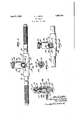
- FIG. 1 is a plan of a tap'wrench constructed in accordance with this invention, and shown in position to hold a tap with the smallest sized shank;
- Fig. 2 is a sectional view on the line 22 of Fig. 1, showing the tap is position;
- Fig. 3 is a sectional view on the line 3-3 of Fig. 1, showing the positive means for holding the adjustment;
- the tap can be inserted from either side through openings 24 in the frame 11.
- a tap wrench having a rod extending through it, the ends of which constitute the handles of the' at right angles to the rod internally threaded, and an opening for allowing the shank of a tap to enter said projection, a jaw movable in said frame at right angles to the axis of the rod and having a right angular notch in its end complementary to the notch in the rod and having a longitudinal groove, and an adjusting screw having a head outside the frame and an external screw-thread for adjusting it in said projection and being hollow and provided With an internal screwthread of the hand opposite to that of its external thread, the jaw having a screwthreaded portion fitting the internal thread, whereby the jaw can be adjusted by the external and internal screw, and a screw
Landscapes
- Engineering & Computer Science (AREA)
- Mechanical Engineering (AREA)
- Details Of Spanners, Wrenches, And Screw Drivers And Accessories (AREA)
Description
April 5, 1932.
V H.' J; SMITH 1,852,226
TAP WRENCH Filed Nov. 18, 1929 mm WWH WLE ZE Patented Apr. 5, 1932 urro STATES F EC HERBERT J". SMITH, OF GBEENFIELD, MASSACHUSETTS, ASSIG'NOR TO THE THREAD- WELL TOOL COMPANY, OF GR-EENFIELD, MASSACHUSETTS, A GORPORATION' OF MASSACHUSETTS TAP WRENCH Application filed November 18, 1929. Serial No. 407,841.
} lation of the parts, and in which taps having different shanks can be inserted and held with equal rigidity; and to provide a comparatively inexpensive and simple construction.
v Other objects and advantages of the invention will appear hereinafter.
Reference is to be had to the accompanying drawings, in which Fig. 1 is a plan of a tap'wrench constructed in accordance with this invention, and shown in position to hold a tap with the smallest sized shank;
Fig. 2 is a sectional view on the line 22 of Fig. 1, showing the tap is position;
Fig. 3 is a sectional view on the line 3-3 of Fig. 1, showing the positive means for holding the adjustment; and
Fig. 4 is a view similar to Fig. 1, showing a tap in position with a much larger shank.
The device is made with a single rod 10 constituting the main portion of the wrench and serving at its two ends as handles. On this is arranged a frame 11 consisting of a single piece, either forging or casting, through which the handle 10 runs and to which it is secured by a pin 12, so that these two parts practically constitute a single element of the devise. The rod or handle 10 is provided with a notch 13 preferably at its center, consisting of two surfaces at right angles to each other, and at 45 degrees to the axial line of the handle.
The frame 11 besides surrounding the rod or handle 10 is provided with a hollow cylindrical projection 14, thus having a T shape. This projection 14 is screw-threaded internally at 15 to provide for receiving a screw 16 having a knurled head 27 by which the adjustment is secured. This screw is hollow and is provided with screw-threads 17 for fitting a screw 18 which has preferably integrally connected with it at the end a jaw 19. One of the screw-threads 15 or 17 is right handed and the other left handed. This jaw is provided with outer surfaces at 90 degrees to each other, parallel with the sur-' faces 13 and adapted to fit against them when in the most retracted position as shown in Fig. 1, and the end is provided with a notch formed of two other surfaces also at right angles to each other and at degrees to the axial line of the handle.
l/Vherever the aw 19 is adjusted, the surfaces 13 and 20 provide a square opening. It is shown in its smallest size in Fig. l and at practically its largest size in Fig. 4. Into this square opening the shank of the tap 21 is inserted.
Of course the operation is to unscrew the screw 16 so as to allow the tap to be inserted against the surfaces 13, and then screw this down until the shank of the tap is fixed in position.
The tap can be inserted from either side through openings 24 in the frame 11.
A side screw 22 is set in with a screwdriver so as to engage in a groove 23 along the side of the jaw 19. This firmly holds the jawin any adjusted position and also prevents the aw from turning when the screw 22 is loosened enough for adjusting purposes.
It will be seen that this constitutes a very simple way to construct a tap wrench with a minimum number of parts and a comparatively small amount of machining. The device is simple, compact and durable and is not likely to get out of repair.
Although I have illustrated and described only one form of the invention, I am aware of the fact that changes can be made therein by any person skilled in the art Without departing from the scope of the invention as expressed in the claim. Therefore I do not wish to be limited to the exact form shown, but what I do claim is As an article of manufacture, a tap wrench having a rod extending through it, the ends of which constitute the handles of the' at right angles to the rod internally threaded, and an opening for allowing the shank of a tap to enter said projection, a jaw movable in said frame at right angles to the axis of the rod and having a right angular notch in its end complementary to the notch in the rod and having a longitudinal groove, and an adjusting screw having a head outside the frame and an external screw-thread for adjusting it in said projection and being hollow and provided With an internal screwthread of the hand opposite to that of its external thread, the jaw having a screwthreaded portion fitting the internal thread, whereby the jaw can be adjusted by the external and internal screw, and a screw extending through the side of the frame transversely and engaging in the groove in the movable jaw to prevent its turning.
In testimony whereof I have hereunto aflixed my signature.
HERBERT J. SMITH.
Priority Applications (1)
| Application Number | Priority Date | Filing Date | Title |
|---|---|---|---|
| US407841A US1852220A (en) | 1929-11-18 | 1929-11-18 | Tap wrench |
Applications Claiming Priority (1)
| Application Number | Priority Date | Filing Date | Title |
|---|---|---|---|
| US407841A US1852220A (en) | 1929-11-18 | 1929-11-18 | Tap wrench |
Publications (1)
| Publication Number | Publication Date |
|---|---|
| US1852220A true US1852220A (en) | 1932-04-05 |
Family
ID=23613744
Family Applications (1)
| Application Number | Title | Priority Date | Filing Date |
|---|---|---|---|
| US407841A Expired - Lifetime US1852220A (en) | 1929-11-18 | 1929-11-18 | Tap wrench |
Country Status (1)
| Country | Link |
|---|---|
| US (1) | US1852220A (en) |
-
1929
- 1929-11-18 US US407841A patent/US1852220A/en not_active Expired - Lifetime
Similar Documents
| Publication | Publication Date | Title |
|---|---|---|
| US1677473A (en) | Socket wrench and screw driver | |
| US2593828A (en) | Handle-container for different size hexagonal wrenches | |
| US1616300A (en) | Screw driver | |
| US1561812A (en) | Wrench | |
| US1852220A (en) | Tap wrench | |
| US914255A (en) | Drill-chuck. | |
| US1410032A (en) | Socket wrench | |
| US1889556A (en) | Tool | |
| US1367407A (en) | Wrench | |
| US1500314A (en) | Wrench | |
| US2662435A (en) | Predetermined torque release wrench | |
| US1403978A (en) | Adjustable wrench | |
| US2624222A (en) | Adjustable jaw internal wrench with threaded handle | |
| US623435A (en) | Albert | |
| US1695949A (en) | Duplex screw driver | |
| US199408A (en) | Improvement in screw-cutting-die holders | |
| US1456358A (en) | Socket wrench | |
| US1304584A (en) | Alligator-wrench. | |
| US482021A (en) | Office | |
| US783845A (en) | Wrench. | |
| US2265238A (en) | Tool chuck | |
| US482749A (en) | Frank mossberg | |
| US2057014A (en) | Gauge for nipple cutters | |
| US1437873A (en) | Pipe wrench | |
| US1190562A (en) | Wrench. |