US1852037A - Lever fastener - Google Patents
Lever fastener Download PDFInfo
- Publication number
- US1852037A US1852037A US512364A US51236431A US1852037A US 1852037 A US1852037 A US 1852037A US 512364 A US512364 A US 512364A US 51236431 A US51236431 A US 51236431A US 1852037 A US1852037 A US 1852037A
- Authority
- US
- United States
- Prior art keywords
- lever
- band
- plate
- seating
- loop
- Prior art date
- Legal status (The legal status is an assumption and is not a legal conclusion. Google has not performed a legal analysis and makes no representation as to the accuracy of the status listed.)
- Expired - Lifetime
Links
- 239000002184 metal Substances 0.000 description 8
- 238000010276 construction Methods 0.000 description 3
- 210000005069 ears Anatomy 0.000 description 3
- 238000009958 sewing Methods 0.000 description 3
- 208000036366 Sensation of pressure Diseases 0.000 description 1
- 230000001154 acute effect Effects 0.000 description 1
- 229920000136 polysorbate Polymers 0.000 description 1
- 230000000717 retained effect Effects 0.000 description 1
Images

Classifications
-
- A—HUMAN NECESSITIES
- A41—WEARING APPAREL
- A41F—GARMENT FASTENINGS; SUSPENDERS
- A41F11/00—Stocking or sock suspenders
- A41F11/12—Stocking or sock suspenders with devices for adjusting the length
-
- Y—GENERAL TAGGING OF NEW TECHNOLOGICAL DEVELOPMENTS; GENERAL TAGGING OF CROSS-SECTIONAL TECHNOLOGIES SPANNING OVER SEVERAL SECTIONS OF THE IPC; TECHNICAL SUBJECTS COVERED BY FORMER USPC CROSS-REFERENCE ART COLLECTIONS [XRACs] AND DIGESTS
- Y10—TECHNICAL SUBJECTS COVERED BY FORMER USPC
- Y10T—TECHNICAL SUBJECTS COVERED BY FORMER US CLASSIFICATION
- Y10T24/00—Buckles, buttons, clasps, etc.
- Y10T24/40—Buckles
- Y10T24/4051—Garment shielded
Definitions
- the invention consists in the provision of a lever having a pressure member or clamp ing bar the side or outer face of which is adapted to engage the main part of the band or webbing so that forces the latter against an ing or support, the edge of or pressure member moving ing with, a shouldered the operation of the lever upstanding seatthe clamping bar over,orco-operatpart or edge disposed adjacent the seating or support and serving to retain the lever in 1ts operative or'clamping position.
- the side or outer face of the pressure member or clamping bar is prefer ably flat, the seating or su ort a ainst which the main part of the band is forced being likewise flat, or substantially fiat, so that the said main part of the band follows "more or less the plane of the said support, and by arranging the latter so that it in line with the loop end complete band or webbing lies substantially of the band, the is caused to hang vertically. At the same time a better grip is obtained on the band or webbing owing to the provision of the seating against which the main part of the band or webbing is clamped.
- the latter may be curled around the lower bar of the loopto form the shoulder for co-operating with th e edge of the pressure member of the lever, the lower part of the plate being bent rearwardly and upwards to extend above and behin d the bottom bar of the loop and constitute the upstanding support or seating against which the main part of the bandis adapted to be clamped.
- the returned end of the band may-be secured be-v tween the said upwardly-directed part of the plate and the front edge of the latter, which maybe curled or folded over the bottom bar of the loop.
- an upwardly directed plate may be soldered-to the bottom bar of the loop and the returned end of the band passed round the plate and bottom bar and secured by sewing. ment the lever may be hinged directly to a metal plate which provides the seating for the main part of the band,the said plate being suitably shaped or stamped up to provide the shouldered'portion.
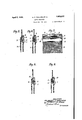
- Figure 1 of the accompanying drawings represents a vertical section through a lever fastener constructed in accordance with this invention and shown applied to the band of a stocking suspender, illustrating the manner in which the main part of the band is clamped against the seating.
- Figure 2 is a front view of the fitting, with the lever raised and the main part of the band disengaged, to show the seating and the shouldered edge with which the edge of the clamping bar of the lever co-operates.
- Figure 3 illustrates a vertical section through a modified construction in which the seating is formed by a plate soldered to the bottom bar of the loop.
- Figure 4c shows another construction which may be employed.
- Figure 5 shows a side view of a further form of fitting.
- Figure 6 represents a vertical section through same.
- Figure 7 is a front view of the fitting shown in Figures 5 and 6 with the lever raised and the main part of the band disengaged.
- F iguresS and 9 represent respectively, side and sectional views of another modified arrangement.
- v tachment plate 5 is firmly the loop by means of a metal attachment plate 5.
- the lever 1 consistsof a sheet metal front part having a turned-over upper edge disposed at an acute angle to the latter to form a narrow flat-sided.
- clamping bar 6 which is adapted to engage the main part of the suspender band, the end portions of the bent-over part being divided and curled around the top bar 2 of the loop to constitute hinge-knuckles 7
- the one edge 9 of the atbar i of the loop by curling or folding it tightly around the same, the opposite end portion 8 of the said plate being bent rearwardly and upwards, so that it extends above and behind the bottom bar 4 of the loop, as illustrated.
- the returned end of the band 3 is inserted between this bent-up rear portion 8 and the curled-over edge 9 of the front part of the plate 5, the said rear portion being then clenched or swedged down on to the band, so that it is firmly clamped between the same and the said curled-over edge..
- the returned end of the band is thus firmly-secured tothe loop, the said end being passed over the top of the swedged-down portion 8 and down at the back of the latter, which I is thus covered and protected.
- the covered front face of the upper end of the said rear part 8 of the attachment plate forms a fiat seating against which the main part of the band is adapted to be clamped by the lever, the said main part of the band passing between'this seating and the lever, over the curled-over front edge 9 of the plate 5.
- This curled-over edge which is covered by the main part of the band, forms a shoulder with which the edge of the clamping bar 6 of the lever co-operates when the said lever is actuatedr
- the loop 2, 4E, bywhich the lever 1 is carried is set forwardly at a small angle to the vertical, and when the lever is operated to clamp the main part of the band, after the latter has been adjusted, the flat outer face of the clamping bar 6 of the lever engages against the said main portion of the band and presses it back against the flat covered seating formed by the upper end of the part 8 of the plate.
- the edge of the clamping bar wipes over the shoulder formed by the curled-over front edge 9 of the said plate, the arrangement being such that the shoulder part serves to give a stiff movement to the lever, and as the latter moves over the dead-centre it is automatically retained by the shoulder in its clamping or operative position.
- the lever is turned down in this manner the main part of the band 3is clamped firmly against thefiat seating so that it is caused to lie in a plane substantially parallel thereto, in line with the lower loop-end of the band.
- the suspender thus hangs vertically when displayed, thereby giving an improved appearance to the V clamped by the lever fixed to the bottom same.
- the lever 1 is of the same construction and is hinged to the top bar 2 of a wire loop as above described.
- the flat seating against which the main part of the band 3 is clamped is, however, formed by a narrow plate 5soldered to the bottom bar 1- of the loop and upstanding therefrom in the manner illustrated.
- the returned end of the band 3 is passed around this plate 5 and around the bottom bar of the loop and secured by sewing.
- the action of the fitting is the'same as in the previous arrangement, the main part of the band being forced. by the outer side of the clamping bar 6 of covered seating,-so that it lies in a plane parallel thereto, the edge of the moving over the shouldered the bottom bar i of the loop, by the main part of tained by the shoulder tion.
- lever 1 may, as shown in Figure 4, .be hinged directly to .a metal plate 5' between ears 10 on the latter, the said plate having a slot 11 at its lower end'through which the returned end of the suspender band 3 is passed, the said end being secured by sewing.
- the plate 5 is shouldered at 12, the shoulder, covered by the mainv part of the band, cooper ating with the edge of the clamping bar 6 of the lever 1 and serving to retain the latter in its turned-down or operative position.
- Figures 5 to 7 show another arrangement in which the wire loop is dispensedwith.
- the lever 1 is hinged to a bar 2 carried by upwardly-extending arms 13 which are integral with a metal plate 5 the lower portion 8 of which is bent rearwardly and upwards to form a flat seating against which the main part of the band 3 is clamped by the lever, the edge of the clamping bar 6 of the lever moving over the shoulder formed by the co'vered upper edge ofthe front part of the plate 5.
- a lever fastener for bands comprising a wire loop, a plate attached to the lower bar of the loop and to which one end of the band is secured, said plate extending upwards above and rearwards of the said lower bar to form an upstanding seating, and a lever pivoted on the upper bar of the loop, said lever having a pressure member adapted to co-operate with the lower bar of the loop and to press the band against the upstanding seatin 2.
- a lever fastener for stocking suspender bands, brace webbing and other bands and the like comprising a frame to which one end of the band is secured, said frame having a transverse shoulder at the front and an'upstanding rear part adjacent to and extending above the shoulder to form a fiat seating for the band or the like, in combination with a lever pivoted to the frame and provided with a pressure part having a flat side which is adapted to engage the band or the like and maintain it closely against the upstanding seating after the edge of the said pressure part has moved over the shoulder, the said edge being presented downwards when the lever is in its operative position.
- a lever fastener for stocking suspender bands, brace webbing and other bands and the like comprising a frame to which one end of the band is secured, said frame having a transverse shoulder at the front and a flat upstanding seating adjacent to and extending above the shoulder, in combination with a lever mounted upon the frame and provided with a clamping part he ving a flat side which is adapted to press the hand against the seating, the edge of the clamping part being presented downwards when the lever is in its operative position and being adapted to co-opcrate with and move over the shoulder to render the lever self-retaining in its fastening position.
- a lever fastener for bands comprising a plate bent to U-section forming spaced sides between which one end of the band is adapted to be clamped, the rear side extending above the top of the front side, a lever supporting part carried by the said plate, and a lever mounted upon the said supporting part in spaced relation to the U-section plate to allow of the main part of the band passing under the lever and over'the front side and upward ly extending part of the rear side of the U- section plate, said lever having a flat sided pressure memberthe edge of which is adapted to move rearwards over'the top of the-front side of the said plate, so that the flat side of the pressure member keeps the band pressed against the said upwardly extending part of the rear side of the said plate, the edge of the pressure member being presented downwards when the lever is in-its operative position.
- a lever fastener for bands comprising a plate to which the one end of theband is secured, said plate having a front shoulder and a flat set-back seating above the shoulder, a loop carried by saidplate and through which the main part of the band passes, and a lever mountedupon the outer part of the loop, said lever being provided with a clamping part having a flat side adapted to engage the band and press, it against the set-back seating of the plate, the edge of the clamping part moving over the shoulder and being downwardly directed when the lever is in its clamping or operative position.
- a lever fastener for bands comprising a U-section frame having a front side whose upper edge is bent over rearwards to form a shoulder and a rear side extending above the said shoulder to form a flat upstanding seating, one end of the band being adapted to be clamped between said front and rear sides, lever supporting means carried by the said frame, and a lever pivoted on said supporting means in spaced relation to the frame, said lever having a pressure member with a flat side adapted to maintain the main part of the band closely against the upstanding seating, the edge of the pressure member being presented downwards when the lever is in its operative position.
- a lever fastener for bands comprising a wire loop, a transverse metal plate bent to a U-shape between the sides of which one end of the band can be clamped and the rear side of which is higher than the front side, said front side being curled over the lower bar of the loop to form a shoulder and the rear side forming a flat upstanding seating above the said lower bar, in combination with a lever hinged upon the upper bar of the loop, said lever being provided with a clamping part having a flat side adapted to maintain the band closely against the upstanding seating, the edge of the clamping part co-operating with the shoulder and being downwardly directed when the lever is in its fastening position.
- a lever fastener for bands comprising a wire loop, a plate attached to the lower bar of the loop and to which one end of the band is secured, said plate extending upwards above and rearwards of the said lower-bar to form a flat upstanding seating, and a lever pivoted new on the upper bar of the loop, said lever having a flat sided pressure member adapted to engage the band and press it against the up standing seating, the lower edge of the pres sure member moving over the lower bar of the 7 loop and being presented downwards when the lever is in its operative position.
- a lever fastener for bands comprising a plate bent to form a horizontal shoulder at thev front and a flat upstanding part above,
Landscapes
- Engineering & Computer Science (AREA)
- Textile Engineering (AREA)
- Buckles (AREA)
Description
April 5, 1932. G. T. WALKER ET AL LEVER FASTENER Filed Jan. 50, 1951' ,2 Sheets-Sheet 1 GILBER'IIEIV7ENTORS WALKE ATTORNEYS April 5, 1932.
G. T. WALKER ET AL LEVER FASTENER Filed Jan. 50, 1931 2 Sheets-Sheet 2 mLw m mA .vT lwm 8 m H w.
Patented Apr. 5, 1932 GILBERT THOIVIAS WALKER AND .HER
on BIRMINGHAM,
mews-TIME...-
BERT HOWARD woon,
ENGLAND LEVER FASTENER Application filed January 30, 1931, Serial No. 512,364, and in Great Britain January 30, 1930 This invention relates to lever fasteners for stocking suspender bands, brace webbing and other bands, straps and the The object of the present invention is provide an improved cons like.
to truction of lever fastener which enables a better grip to be obtained on the band or webbing and which gives a more attractive appearance to the suspender or other article to which it is applied when the suspender or article is displayed, for example in a show-room, shop window or the like, by causing the band or webbing to hang down vertically, with the band substantially the main part of in line with the lower loop portion of the same, instead ofthe loop end hanging out of line, as other fittings are used.
is the case where The invention consists in the provision of a lever having a pressure member or clamp ing bar the side or outer face of which is adapted to engage the main part of the band or webbing so that forces the latter against an ing or support, the edge of or pressure member moving ing with, a shouldered the operation of the lever upstanding seatthe clamping bar over,orco-operatpart or edge disposed adjacent the seating or support and serving to retain the lever in 1ts operative or'clamping position. The side or outer face of the pressure member or clamping bar is prefer ably flat, the seating or su ort a ainst which the main part of the band is forced being likewise flat, or substantially fiat, so that the said main part of the band follows "more or less the plane of the said support, and by arranging the latter so that it in line with the loop end complete band or webbing lies substantially of the band, the is caused to hang vertically. At the same time a better grip is obtained on the band or webbing owing to the provision of the seating against which the main part of the band or webbing is clamped. In applying the invention to a fitting embodying a wire loop and a depending metal attachment plate, the latter may be curled around the lower bar of the loopto form the shoulder for co-operating with th e edge of the pressure member of the lever, the lower part of the plate being bent rearwardly and upwards to extend above and behin d the bottom bar of the loop and constitute the upstanding support or seating against which the main part of the bandis adapted to be clamped. The returned end of the band may-be secured be-v tween the said upwardly-directed part of the plate and the front edge of the latter, which maybe curled or folded over the bottom bar of the loop. If desired, an upwardly directed plate may be soldered-to the bottom bar of the loop and the returned end of the band passed round the plate and bottom bar and secured by sewing. ment the lever may be hinged directly to a metal plate which provides the seating for the main part of the band,the said plate being suitably shaped or stamped up to provide the shouldered'portion.
Figure 1 of the accompanying drawings represents a vertical section through a lever fastener constructed in accordance with this invention and shown applied to the band of a stocking suspender, illustrating the manner in which the main part of the band is clamped against the seating.
Figure 2 is a front view of the fitting, with the lever raised and the main part of the band disengaged, to show the seating and the shouldered edge with which the edge of the clamping bar of the lever co-operates.
Figure 3 illustrates a vertical section through a modified construction in which the seating is formed by a plate soldered to the bottom bar of the loop.
Figure 4c shows another construction which may be employed. 7 Figure 5 shows a side view of a further form of fitting.
Figure 6 represents a vertical section through same.
Figure 7 is a front view of the fitting shown in Figures 5 and 6 with the lever raised and the main part of the band disengaged.
F iguresS and 9 represent respectively, side and sectional views of another modified arrangement. a
Referring to Figures 1 and 2 of the improved fit-ting the same'comprises a lever 1 hinged to the top bar 2 of an elongated wire loop, the usual returned end of the Suspender band 8 being secured to the bottom bar 4: of
In another arrangev tachment plate 5 is firmly the loop by means of a metal attachment plate 5. The lever 1 consistsof a sheet metal front part having a turned-over upper edge disposed at an acute angle to the latter to form a narrow flat-sided. clamping bar 6 which is adapted to engage the main part of the suspender band, the end portions of the bent-over part being divided and curled around the top bar 2 of the loop to constitute hinge-knuckles 7 The one edge 9 of the atbar i of the loopby curling or folding it tightly around the same, the opposite end portion 8 of the said plate being bent rearwardly and upwards, so that it extends above and behind the bottom bar 4 of the loop, as illustrated. The returned end of the band 3 is inserted between this bent-up rear portion 8 and the curled-over edge 9 of the front part of the plate 5, the said rear portion being then clenched or swedged down on to the band, so that it is firmly clamped between the same and the said curled-over edge.. The returned end of the band is thus firmly-secured tothe loop, the said end being passed over the top of the swedged-down portion 8 and down at the back of the latter, which I is thus covered and protected. The covered front face of the upper end of the said rear part 8 of the attachment plate forms a fiat seating against which the main part of the band is adapted to be clamped by the lever, the said main part of the band passing between'this seating and the lever, over the curled-over front edge 9 of the plate 5. This curled-over edge, which is covered by the main part of the band, forms a shoulder with which the edge of the clamping bar 6 of the lever co-operates when the said lever is actuatedr The loop 2, 4E, bywhich the lever 1 is carried is set forwardly at a small angle to the vertical, and when the lever is operated to clamp the main part of the band, after the latter has been adjusted, the flat outer face of the clamping bar 6 of the lever engages against the said main portion of the band and presses it back against the flat covered seating formed by the upper end of the part 8 of the plate. At the same time the edge of the clamping bar wipes over the shoulder formed by the curled-over front edge 9 of the said plate, the arrangement being such that the shoulder part serves to give a stiff movement to the lever, and as the latter moves over the dead-centre it is automatically retained by the shoulder in its clamping or operative position. Then the lever is turned down in this manner the main part of the band 3is clamped firmly against thefiat seating so that it is caused to lie in a plane substantially parallel thereto, in line with the lower loop-end of the band. The suspender thus hangs vertically when displayed, thereby giving an improved appearance to the V clamped by the lever fixed to the bottom same. The arrangement also enables a better grip to be obtained on the band which is firmly against the covered seating, the upward pull on the band tending to draw the clamping bar-6 of the lever more closely against the band. In the arrangement illustrated in Figure 3 of the drawings, the lever 1 is of the same construction and is hinged to the top bar 2 of a wire loop as above described. The flat seating against which the main part of the band 3 is clamped is, however, formed by a narrow plate 5soldered to the bottom bar 1- of the loop and upstanding therefrom in the manner illustrated. The returned end of the band 3 is passed around this plate 5 and around the bottom bar of the loop and secured by sewing. The action of the fitting is the'same as in the previous arrangement, the main part of the band being forced. by the outer side of the clamping bar 6 of covered seating,-so that it lies in a plane parallel thereto, the edge of the moving over the shouldered the bottom bar i of the loop, by the main part of tained by the shoulder tion.
Instead of the lever 1 being hinged to a wire loop. it may, as shown in Figure 4, .be hinged directly to .a metal plate 5' between ears 10 on the latter, the said plate having a slot 11 at its lower end'through which the returned end of the suspender band 3 is passed, the said end being secured by sewing. The plate 5 is shouldered at 12, the shoulder, covered by the mainv part of the band, cooper ating with the edge of the clamping bar 6 of the lever 1 and serving to retain the latter in its turned-down or operative position. The upper part of the plate part formedby wh ch is covered in its operative posi- 5, above the shoulder 12, is flat, and forms a seating against which the main part of the band 3 is pressed, the said band being engaged by the flat outer face of the clamping bar of the lever as the latter is moved down. Owing to the flat seating against which the main part of the band is clamped it is caused to hang down substantially in line with the lower loop end of the band, as in the previous arrangements. 7
Figures 5 to 7 show another arrangement in which the wire loop is dispensedwith. In this arrangement the lever 1 is hinged to a bar 2 carried by upwardly-extending arms 13 which are integral with a metal plate 5 the lower portion 8 of which is bent rearwardly and upwards to form a flat seating against which the main part of the band 3 is clamped by the lever, the edge of the clamping bar 6 of the lever moving over the shoulder formed by the co'vered upper edge ofthe front part of the plate 5.
' A somewhat similar type of fitting is illustrated in Figures 8 and mounted between arms 13 on a sheet metal clamping bar 6 9, the lever 1 being the lever against thev fiat the band, so that it is rep plate, asin the previous arrangement, but the lower portion 8 of the plate is bent forwardly instead of rearwardly and swedged down on to the band, the seating being formed by the upper part 5 of the plate, which extends above the part 8 of the latter, as shown.
Although the fitting has been described in connection with the band of a stocking suspender it may be applied to other bands or straps, or to brace webbing or the like.
Having fully described our invention, what we desire to claim and secure by Letters Patent is l. A lever fastener for bands comprising a wire loop, a plate attached to the lower bar of the loop and to which one end of the band is secured, said plate extending upwards above and rearwards of the said lower bar to form an upstanding seating, and a lever pivoted on the upper bar of the loop, said lever having a pressure member adapted to co-operate with the lower bar of the loop and to press the band against the upstanding seatin 2. A lever fastener for stocking suspender bands, brace webbing and other bands and the like, comprising a frame to which one end of the band is secured, said frame having a transverse shoulder at the front and an'upstanding rear part adjacent to and extending above the shoulder to form a fiat seating for the band or the like, in combination with a lever pivoted to the frame and provided with a pressure part having a flat side which is adapted to engage the band or the like and maintain it closely against the upstanding seating after the edge of the said pressure part has moved over the shoulder, the said edge being presented downwards when the lever is in its operative position.
3. A lever fastener for stocking suspender bands, brace webbing and other bands and the like, comprising a frame to which one end of the band is secured, said frame having a transverse shoulder at the front and a flat upstanding seating adjacent to and extending above the shoulder, in combination with a lever mounted upon the frame and provided with a clamping part he ving a flat side which is adapted to press the hand against the seating, the edge of the clamping part being presented downwards when the lever is in its operative position and being adapted to co-opcrate with and move over the shoulder to render the lever self-retaining in its fastening position.
4. A lever fastener for bands, comprising a plate bent to U-section forming spaced sides between which one end of the band is adapted to be clamped, the rear side extending above the top of the front side, a lever supporting part carried by the said plate, and a lever mounted upon the said supporting part in spaced relation to the U-section plate to allow of the main part of the band passing under the lever and over'the front side and upward ly extending part of the rear side of the U- section plate, said lever having a flat sided pressure memberthe edge of which is adapted to move rearwards over'the top of the-front side of the said plate, so that the flat side of the pressure member keeps the band pressed against the said upwardly extending part of the rear side of the said plate, the edge of the pressure member being presented downwards when the lever is in-its operative position. p
5. A lever fastener for bands comprising a plate to which the one end of theband is secured, said plate having a front shoulder and a flat set-back seating above the shoulder, a loop carried by saidplate and through which the main part of the band passes, and a lever mountedupon the outer part of the loop, said lever being provided with a clamping part having a flat side adapted to engage the band and press, it against the set-back seating of the plate, the edge of the clamping part moving over the shoulder and being downwardly directed when the lever is in its clamping or operative position.
6. A lever fastener for bands comprising a U-section frame having a front side whose upper edge is bent over rearwards to form a shoulder and a rear side extending above the said shoulder to form a flat upstanding seating, one end of the band being adapted to be clamped between said front and rear sides, lever supporting means carried by the said frame, and a lever pivoted on said supporting means in spaced relation to the frame, said lever having a pressure member with a flat side adapted to maintain the main part of the band closely against the upstanding seating, the edge of the pressure member being presented downwards when the lever is in its operative position. 7
7. A lever fastener for bands comprising a wire loop, a transverse metal plate bent to a U-shape between the sides of which one end of the band can be clamped and the rear side of which is higher than the front side, said front side being curled over the lower bar of the loop to form a shoulder and the rear side forming a flat upstanding seating above the said lower bar, in combination with a lever hinged upon the upper bar of the loop, said lever being provided with a clamping part having a flat side adapted to maintain the band closely against the upstanding seating, the edge of the clamping part co-operating with the shoulder and being downwardly directed when the lever is in its fastening position. I
8. A lever fastener for bands comprising a wire loop, a plate attached to the lower bar of the loop and to which one end of the band is secured, said plate extending upwards above and rearwards of the said lower-bar to form a flat upstanding seating, and a lever pivoted new on the upper bar of the loop, said lever having a flat sided pressure member adapted to engage the band and press it against the up standing seating, the lower edge of the pres sure member moving over the lower bar of the 7 loop and being presented downwards when the lever is in its operative position.
9. A lever fastener for bands comprising a plate bent to form a horizontal shoulder at thev front and a flat upstanding part above,
7 the shoulder, means. for attaching one end of the band to the plate, forwardly-extending ears. on the upper part of the plate, and a lever pivoted between said ears, said lever being provided with a clamping part having a flat side adapted to maintain the band closely against the upstanding part above the shoulder, the edge of the clamping part co-operating with the shoulder and being downwardlypresented' when the lever isv in its fastening position.
In testimony whereof we: have afl'i'xed our signatures.
GILBERT THOMAS WALKER. HERBERT HOWARD WOOD.
Applications Claiming Priority (1)
| Application Number | Priority Date | Filing Date | Title |
|---|---|---|---|
| GB23193/30A GB341839A (en) | 1930-01-30 | 1930-01-30 | Improvements relating to lever fasteners for suspender bands, brace webbing and other bands, straps and the like |
Publications (1)
| Publication Number | Publication Date |
|---|---|
| US1852037A true US1852037A (en) | 1932-04-05 |
Family
ID=10191653
Family Applications (1)
| Application Number | Title | Priority Date | Filing Date |
|---|---|---|---|
| US512364A Expired - Lifetime US1852037A (en) | 1930-01-30 | 1931-01-30 | Lever fastener |
Country Status (2)
| Country | Link |
|---|---|
| US (1) | US1852037A (en) |
| GB (1) | GB341839A (en) |
-
1930
- 1930-01-30 GB GB23193/30A patent/GB341839A/en not_active Expired
-
1931
- 1931-01-30 US US512364A patent/US1852037A/en not_active Expired - Lifetime
Also Published As
| Publication number | Publication date |
|---|---|
| GB341839A (en) | 1931-01-22 |
Similar Documents
| Publication | Publication Date | Title |
|---|---|---|
| US1852037A (en) | Lever fastener | |
| US1821839A (en) | Apparel buckle | |
| US1781709A (en) | Buckle | |
| US2219537A (en) | Buckle | |
| US2377287A (en) | Buckle | |
| CN209776320U (en) | Seat back with storage box | |
| US2007436A (en) | Buckle | |
| US2088820A (en) | Buckle | |
| US597511A (en) | Curtain-fastener | |
| US1876383A (en) | Slide | |
| US2211187A (en) | Buckle | |
| US952619A (en) | Suspender-buckle. | |
| US1775929A (en) | Belt retainer | |
| US1509461A (en) | Pinch support for garments (woven or knitted goods) | |
| US2964817A (en) | Fastening devices for wearing apparel | |
| US5361460A (en) | Tie clip mounted behind a tie | |
| US1338535A (en) | Buckle | |
| US2697260A (en) | Buckle | |
| GB351301A (en) | Improvements relating to fasteners or adjusting devices for use in connection with bands, webbings, straps and the like | |
| US1332628A (en) | Buckle | |
| US1454440A (en) | Rustless buckle | |
| US333495A (en) | Garment-supporting clasp | |
| US1649766A (en) | Double-pointed-pin fastener | |
| US1883009A (en) | Buckle | |
| USRE15982E (en) | Facturing co |