US1852027A - Creel - Google Patents
Creel Download PDFInfo
- Publication number
- US1852027A US1852027A US240947A US24094727A US1852027A US 1852027 A US1852027 A US 1852027A US 240947 A US240947 A US 240947A US 24094727 A US24094727 A US 24094727A US 1852027 A US1852027 A US 1852027A
- Authority
- US
- United States
- Prior art keywords
- spool
- drum
- full
- yarn
- arms
- Prior art date
- Legal status (The legal status is an assumption and is not a legal conclusion. Google has not performed a legal analysis and makes no representation as to the accuracy of the status listed.)
- Expired - Lifetime
Links
- 238000009987 spinning Methods 0.000 description 11
- 230000033001 locomotion Effects 0.000 description 6
- 230000005484 gravity Effects 0.000 description 4
- 238000010276 construction Methods 0.000 description 3
- 241000702021 Aridarum minimum Species 0.000 description 1
- 238000000151 deposition Methods 0.000 description 1
- 238000012053 enzymatic serum creatinine assay Methods 0.000 description 1
Images
Classifications
-
- D—TEXTILES; PAPER
- D01—NATURAL OR MAN-MADE THREADS OR FIBRES; SPINNING
- D01G—PRELIMINARY TREATMENT OF FIBRES, e.g. FOR SPINNING
- D01G15/00—Carding machines or accessories; Card clothing; Burr-crushing or removing arrangements associated with carding or other preliminary-treatment machines
- D01G15/02—Carding machines
- D01G15/12—Details
- D01G15/46—Doffing or like arrangements for removing fibres from carding elements; Web-dividing apparatus; Condensers
- D01G15/62—Slubbing-winding apparatus
Definitions
- My invention relates to crcels used on spinning machines, in Which the roving that 1s to be spun into yarn is contained on large spools or beams. These spools, when full of roving, are so long and cumbersome that it requires considerable exertion on the part of the operator to properly place a spool in its normal operative position in the supporting creels above the driving drinn of the machine.
- Another object of the invention is to provide means for placing a full Spool in its usual operative position on the driving drum, with a. minimum amount of exertion on the part of the operator.
- Figure 1 is a sectional end elevation of a portion of the upper part of a Spinning inachine, showing the roll beams and driving drum, an empty roving Spool in position on the drum, and a full spool supported by my improved creel construction;
- Fig. 2 is a 'side elevationon one section of a spinningmachine Showing the driving drum and a full spool mounted thereon between two creel stands; i
- Fig 3 is a plan vievv of the mechanism shown in Fig. 1, With the spools removed;
- Fig. 4 is an end'elevation of the spool latch holder and its counterbalance arm
- Fig. 5 is a side view of the same.
- Each creel stand 21 comprises a base, an
- each of these arms 24 is an extension 28, the lower end of which is Y vprovided With a hole29 in which af cross" rod 30 is fixed.
- the two arms 24 arel thus rigidly held together, whereby the operator can swing thearms, with' a full spool 17 thereon, to Vany predeterminedposition, as. indicated by .full and dotted' lines in-Fig. ⁇ 1.
- each replenishing arm 24 Projecting from the outer side lof each replenishing arm 24, intermediate theltrunnion notch 26 and ful'crum pin 27, is al stud 31 c0- operating with aV latch 32 Swingably mounted on a. stud 33, said Stud being fixed tothe inner side ofla supporting lever 34tvhichjin turn VisiiXed to a shaft 35, svvingable in bearings ontheV creel uprights 23.
- the latches .32 are provided vvith notchesffBG 4and 37 Jfor the lreception of thestuds 31 inthe various positions of the replenishing arms'.
- the latches are maintainedjagainstthe studsby the counter ⁇ - balancing WeightsA 38.- Y. Y
- said hooks serving as holders for the trunnions of an empty spool before its final removal from the machine.
- I In order to facilitate the ,removal of an empty spool 2O from its position on the drum, Iprovide spool lifting arms 41 mounted at each end of a shaft that is in a swingable relation with the creel uprights. Preferably these arms 41 are attached to ahollow shaft 42 (see Fig. 2), loosely pivoted on the latch holder shaft 35. The free ends of the arms 41 extend beneath the spool trunnions 18 and rest on stop pins 44.
- the operator swings the arms 41 by means of a handle 43 fixed to the shaft 42, so that the empty spool is lifted up and the trunnions 18 are raised out of their guideways 19 in the Creel, whereupon the spoolrolls by gravity down the inclined ways 39 into the receiving hooks 40.
- the 0perator In the operation of removing lan empty spool and replacing with a full one, the 0perator first places the trunnions of a full spool in the notches of the replenishing arms 24 when at vtheir lowest position (shown in dotted lines in Fig. 1). I-Ie then swings the arms upward till the pins 31 catch in the upper notches 37 of the latches 32. Then he actuates the empty spool remover until the trunnions 18 leave the guideways 19 and roll down to the hooks 40 on the arms 39. rfhen he pushes the trunnions of the full spool out of the V-shaped notches 26 and the full spool rolls or slides by gravity down the-inclined surfaces 25 to the guideways 19.
- a spinning frame a driving drum, a yarn spool, means to'rotate said yarn spool in operative relation to said drum, said retaining means and said yarn spool being relatively movable to permit a gravity-actuated movement' of said spool toward said drum as the yarn is unwound from said spool, and a supporting structure movably mounted on said spinning frame and eective to receive and support a fullY yarn spool as it is presented and elevatedto reserve position Y and also eifectiveto retain saidgelevate'd yarn spool in "reserve position and to guide said elevated yarn spool to operative position on said driving drum.
- a driving drum a yarn spool, means to retain said yarn spool in operative relation to said drum, said retaining means and said yarn spool being rel atively movable Vtoy permit a gravity-actu.- ated movement of said spool toward said drum as the yarn is unwound from said spool, a support for a full yarn spool,pm'anually movable to raisedposition with said spool, and means to hold said supportin such raised position after manual elevation thereof, said support having guiding portions along which said spool is movable by gravity to operative relation with said drum.
Landscapes
- Engineering & Computer Science (AREA)
- Textile Engineering (AREA)
- Spinning Or Twisting Of Yarns (AREA)
Description
E. D. RHODES April I5, 1932..
CREEL Filed Dec. 19. 1927 3 Sheets-Sheet A TTORN E Y.
' CREEL.
Filed Dec. 19, 1927 3 SheetS-Sheet 2 I N VEN TOR:
Y M @Zlio/alu,
TTORNEY.
April 5, 1932.
E. D. RHODES CREEL Filed Deo. 19, 192'7 5 Sheets-Sheet i5 A .INVENTQRJ Cia/j @lfm/af, @W Qxw Patented Apr. 5, 1932 UNITED STATES' PATENT ortica EARLVD. RHODES, or' TROY, NEW YORK, Assieivonj To WnI'TIN'inAoninn WORKS, OF ,A
Y WHITTNSVILLE, MASSACHUSETTS, A CORPORATION or MASSACHUSETTS CREE'L Application filed December 19V, 1927. Serial No. 240,947.
My invention relates to crcels used on spinning machines, in Which the roving that 1s to be spun into yarn is contained on large spools or beams. These spools, when full of roving, are so long and cumbersome that it requires considerable exertion on the part of the operator to properly place a spool in its normal operative position in the supporting creels above the driving drinn of the machine.
It is one of the objects of the invention to provide means for readily removing an empty spool from its position on the driving drum and for depositing it in holders, Whence it may subsequently be removed by the operator.
Another object of the invention is to provide means for placing a full Spool in its usual operative position on the driving drum, with a. minimum amount of exertion on the part of the operator.
These obj ects are attained by the construction that is illust-rated in the accompanying dra-Wings, in which: Y
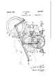
Figure 1 is a sectional end elevation of a portion of the upper part of a Spinning inachine, showing the roll beams and driving drum, an empty roving Spool in position on the drum, and a full spool supported by my improved creel construction;
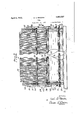
Fig. 2 is a 'side elevationon one section of a spinningmachine Showing the driving drum and a full spool mounted thereon between two creel stands; i
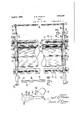
Fig 3 is a plan vievv of the mechanism shown in Fig. 1, With the spools removed;
Fig. 4 is an end'elevation of the spool latch holder and its counterbalance arm; and
Fig. 5 is a side view of the same.
It is to be understood that in the type oi Spinning machine to Which my invention is particularly adapted there are a plurality oi' driving drums, one for each roving spool, saidV spools having heads which overhan the ends of the drum, and the periphery of the drum being in contact With the roving. For the purpose of explaining my invention only one drum or section is shown in the drawings. Y
Referring to the drawings, and 11 (Fig.
'stands' 21, the bases of which are iiXedlyr mounted on the top of the bridge stands 14 at each end of the drum 16. Y
Each creel stand 21 comprises a base, an
empty spool supporting upright 22, anda Y full spool vsnpy'iortin'gupright 23, With the spool retaining guideways 19 formed between them. A spool replenishing arm 24, having a flat upper surface terminating in a V shaped notch 26, is swingably mounted A,on a fulcrumpin 27, at. thetop ofeach full spool supporting upright 23; vThese arms 24 are spaced apa-rt a sutiicient distance to allow a spool inserted between them to `freely rotate onl its trufnni'ons When held in the notches 2G; vExtending downwardly from the notched portion or" each of these arms 24 is an extension 28, the lower end of which is Y vprovided With a hole29 in which af cross" rod 30 is fixed. The two arms 24 arel thus rigidly held together, whereby the operator can swing thearms, with' a full spool 17 thereon, to Vany predeterminedposition, as. indicated by .full and dotted' lines in-Fig. `1. l, I Projecting from the outer side lof each replenishing arm 24, intermediate theltrunnion notch 26 and ful'crum pin 27, is al stud 31 c0- operating with aV latch 32 Swingably mounted on a. stud 33, said Stud being fixed tothe inner side ofla supporting lever 34tvhichjin turn VisiiXed to a shaft 35, svvingable in bearings ontheV creel uprights 23. The latches .32 are provided vvith notchesffBG 4and 37 Jfor the lreception of thestuds 31 inthe various positions of the replenishing arms'. The latches are maintainedjagainstthe studsby the counter`- balancing WeightsA 38.- Y. Y
Projecting from the topofeach upright'22 `is aninclined arm39, terminatingin-ahook 3;
40, said hooks serving as holders for the trunnions of an empty spool before its final removal from the machine.
In order to facilitate the ,removal of an empty spool 2O from its position on the drum, Iprovide spool lifting arms 41 mounted at each end of a shaft that is in a swingable relation with the creel uprights. Preferably these arms 41 are attached to ahollow shaft 42 (see Fig. 2), loosely pivoted on the latch holder shaft 35. The free ends of the arms 41 extend beneath the spool trunnions 18 and rest on stop pins 44. The operator swings the arms 41 by means of a handle 43 fixed to the shaft 42, so that the empty spool is lifted up and the trunnions 18 are raised out of their guideways 19 in the Creel, whereupon the spoolrolls by gravity down the inclined ways 39 into the receiving hooks 40.
In the operation of removing lan empty spool and replacing with a full one, the 0perator first places the trunnions of a full spool in the notches of the replenishing arms 24 when at vtheir lowest position (shown in dotted lines in Fig. 1). I-Ie then swings the arms upward till the pins 31 catch in the upper notches 37 of the latches 32. Then he actuates the empty spool remover until the trunnions 18 leave the guideways 19 and roll down to the hooks 40 on the arms 39. rfhen he pushes the trunnions of the full spool out of the V-shaped notches 26 and the full spool rolls or slides by gravity down the-inclined surfaces 25 to the guideways 19.
By this construction, the removal of an empty spool and its replacement by a full one is easily accomplished by one operato r,`where as in machines as at present constructed, this work often requires the services of two operators. In order to return the arms 24 to their initial lower position, the operator merely raises the arms until the studs 30 pass above the pawls 32 which then swing outward with the weighted levers 34, permitting the studs 31 to pass downward at the vrear of the pawls 32.
Having thus described `my invention and the advantages thereof, I do not wish to bef limited to the details herein disclosed,-otherwise than as set forth in the claims, but what I claim is `f 1. In a spinning frame, a driving drum, a yarn spool, means to'rotate said yarn spool in operative relation to said drum, said retaining means and said yarn spool being relatively movable to permit a gravity-actuated movement' of said spool toward said drum as the yarn is unwound from said spool, and a supporting structure movably mounted on said spinning frame and eective to receive and support a fullY yarn spool as it is presented and elevatedto reserve position Y and also eifectiveto retain saidgelevate'd yarn spool in "reserve position and to guide said elevated yarn spool to operative position on said driving drum.
2. In a spinning frame, a driving drum, a yarn spool, means to retain said yarn spool in operative relation to said drum, said retaining means and said yarn spool being rel atively movable Vtoy permit a gravity-actu.- ated movement of said spool toward said drum as the yarn is unwound from said spool, a support for a full yarn spool,pm'anually movable to raisedposition with said spool, and means to hold said supportin such raised position after manual elevation thereof, said support having guiding portions along which said spool is movable by gravity to operative relation with said drum.
3. The combination in a spinning frame as set forth Vin claim 2, in which the means for holding the support in raised position is releasable by further upward movement of said support.
4. A spinning frame, adriving drum, a yarnv spool having ,projectingr trunnions, frame members having substantially vertical guideways for said trunnions, said frame members and said trunnions being relatively movable to permit gravity-actuated move ment of said yarn spool toward said drum as the yarn is unwound therefrom, guiding members associated with said guideways and pivoted to said spinning frame, said guiding members being manually movable to raised position after a full yarn spool has been placed thereon, and means to hold said members in raised. position, said guidingk members being inclined downwardly toward said guideways when in such raised position so that a full yarn spool may be .advanced by gravity to said guideways along said guiding members.
5. The combination in a spinning frame as set forth in claim 4, in which means is provided for kreleasing said guidingmembers by further upward movement thereof. p
6. The combination in a spinning frame as set forth in claim 4, in which latches are pro vided to hold said guiding members in raised position', said latches being releasable by further upward movement of said members.
In testimony whereof I have signed this specification.
y EARL D. RHODES.
Priority Applications (1)
| Application Number | Priority Date | Filing Date | Title |
|---|---|---|---|
| US240947A US1852027A (en) | 1927-12-19 | 1927-12-19 | Creel |
Applications Claiming Priority (1)
| Application Number | Priority Date | Filing Date | Title |
|---|---|---|---|
| US240947A US1852027A (en) | 1927-12-19 | 1927-12-19 | Creel |
Publications (1)
| Publication Number | Publication Date |
|---|---|
| US1852027A true US1852027A (en) | 1932-04-05 |
Family
ID=22908590
Family Applications (1)
| Application Number | Title | Priority Date | Filing Date |
|---|---|---|---|
| US240947A Expired - Lifetime US1852027A (en) | 1927-12-19 | 1927-12-19 | Creel |
Country Status (1)
| Country | Link |
|---|---|
| US (1) | US1852027A (en) |
Cited By (1)
| Publication number | Priority date | Publication date | Assignee | Title |
|---|---|---|---|---|
| US2953821A (en) * | 1955-12-01 | 1960-09-27 | Deering Milliken Res Corp | Receiving and positioning apparatus |
-
1927
- 1927-12-19 US US240947A patent/US1852027A/en not_active Expired - Lifetime
Cited By (1)
| Publication number | Priority date | Publication date | Assignee | Title |
|---|---|---|---|---|
| US2953821A (en) * | 1955-12-01 | 1960-09-27 | Deering Milliken Res Corp | Receiving and positioning apparatus |
Similar Documents
| Publication | Publication Date | Title |
|---|---|---|
| GB418411A (en) | Improvements in or relating to cop winding machines | |
| US1852027A (en) | Creel | |
| US2001100A (en) | Spool holder | |
| US3344593A (en) | Doffing machine | |
| US1889839A (en) | Spool stand | |
| US1962661A (en) | Laundry bag holding means | |
| GB152893A (en) | Automatic doffing apparatus for the simultaneous removal of full bobbins or cops on spinning and twisting machines and also the simultaneous mounting of empty bobbins ortubes to take the places of the removed full ones | |
| US1669769A (en) | Combined doffer and donning mechanism | |
| US2505567A (en) | Spool release for spinning frames | |
| US1706826A (en) | Yarn spool | |
| US869044A (en) | Apparatus for doffing spools from the spindles of fly-frames. | |
| US1752678A (en) | Doffing mechanism for spinning, twisting, and like machines | |
| US1579257A (en) | Doffing mechanism for cap spinning, doubling, twisting, and like machines | |
| US2029226A (en) | Apparatus for the manufacture of artificial silk | |
| USRE15604E (en) | Doeeing apparatus | |
| US1790818A (en) | Chine works | |
| US1798516A (en) | Winding or spooling machine | |
| US2128903A (en) | Silk reeling machine | |
| US1983000A (en) | Doffing mechanism for flyer spinning, doubling, twisting, and like machines | |
| US2551070A (en) | Crochet thread holder | |
| US1645083A (en) | Automatic doff latch | |
| US1608912A (en) | Doffing and donning mechanism | |
| SU58891A1 (en) | Spinning machine for fibrous materials | |
| US1543618A (en) | Spinning, twisting, and analogous machine | |
| US1714529A (en) | Doffing mechanism for flyer spinning |