US1851975A - Binder - Google Patents
Binder Download PDFInfo
- Publication number
- US1851975A US1851975A US385797A US38579729A US1851975A US 1851975 A US1851975 A US 1851975A US 385797 A US385797 A US 385797A US 38579729 A US38579729 A US 38579729A US 1851975 A US1851975 A US 1851975A
- Authority
- US
- United States
- Prior art keywords
- binder
- frame
- pamphlet
- back portion
- shaped frame
- Prior art date
- Legal status (The legal status is an assumption and is not a legal conclusion. Google has not performed a legal analysis and makes no representation as to the accuracy of the status listed.)
- Expired - Lifetime
Links
- 239000011230 binding agent Substances 0.000 title description 16
- 210000005069 ears Anatomy 0.000 description 3
- 239000002184 metal Substances 0.000 description 3
- 238000010276 construction Methods 0.000 description 1
Images

Classifications
-
- B—PERFORMING OPERATIONS; TRANSPORTING
- B42—BOOKBINDING; ALBUMS; FILES; SPECIAL PRINTED MATTER
- B42F—SHEETS TEMPORARILY ATTACHED TOGETHER; FILING APPLIANCES; FILE CARDS; INDEXING
- B42F11/00—Filing appliances with separate intermediate holding means
- B42F11/02—Filing appliances with separate intermediate holding means engaging folds
Definitions
- This invention relates to a pamphlet binder of that type in which a plurality of catalogues or trade journals, or books may be removably confined.
- the invention concerns 6i itself more directly with the means for supporting the pamphlets and involves a structure which can be swung beyond one end of the binder for the purpose of assembling the pamphlets.
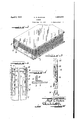
- Figure 1 is an interior fragmentary plan view of the binder showing the pamphlet conning means in dotted lines in its swung-out position.
- Figure 2 is a perspective view ofthe binder with a number of pamphlets confined therein.
- Figure 3 is an enlarged fragmentary sectional view taken in a plane transverse of the pamphlet confining means.
- Figure 4 is an enlarged sectional view taken upon the line IV-IV of Figure 3 looking in the direction of the arrows.
- a binder consisting of the side cover members 1 and a back member 2 as is usual in the art.
- a pair of angle members 3 and 4 are secured along the lateral margin of the back 2 adjacent the upper end thereof as shown in Figures 1 and 3.
- These angle members have one flange attached to the back of the binder with the other flange directed upwardly at right angles thereto.
- a U-shaped metal clip 5 which extends transversely of the back of the binder and is provided with upstanding apertured ears 6.
- a Ushaped metal frame 7 is pivoted at the end of its arm upon the upstanding ears 6 by means of a rod 5a which rod extends through the aper- Y tured portion of the ears 6 and connects the ends of the arms of the frame 7
- a rod 8 ex- Figure 5 is a side elevational view of the4 tendstransversely of the upper end of the assume any convenient form, in the present ⁇ instance it vhas been illustrated as consisting of a pair of resilient metal strips 10 which eX- tend through suitable keepers 11 struck from the upstanding flanges.
- the resilient strips 10 carry pintles 12 which are adapted for eX- tending through apertures in the upstanding flanges of the angles 3 and 4 and through apertures in the U-shaped frame 7.
- the resilient strips and, pins 12 constitute latching ⁇ means for latching the U-frame 7 in its operative position.
- Vhen the resilientl f strips 10 are pulled outwardly as shown in Vdotted lines in Figure 1, the U-fram'e may be swung into the position shown in'dotted lines in Figure 1.
- the pamphlets V may be readily suspended upon the supporting rod 9, and the frame may thus be swung over the cover andthe pintles 112 upon the resilient strips 10 ⁇ may be engaged with the Ueframe as is obvious.
- the resilient strips 10 will ofcourse snap back into their normal position. It'is necessary to deflect them again before the U-shaped frame 7 can be latched in its op erative position.
- a pamphlet binder comprising a back portion, a rod secured to one end of said back portion, a U-shaped frame having the vends of its arms pivoted to said rod and swingable toward and away from said back member, pamphlet-supporting means carried by said U-frame and said rod, and means for latching said U-shaped frame to said back member.
- a pamphlet binder comprising a back portion, a rod secured to one end of said back portion, a U-shaped frame pivoted to said rod, -a pair of angle members secured to the opposite end of said back portion, resilient latching members secured to said angle members, said U-shaped frame being swingable between said angle members, and means on said latch members for latohing said U-shaped frame to said angle members.
- a pamphlet binder Comprising a cover member, a frame pivoted to one end of said cover member and swingable to a position within said cover member, pamphlet-contining means Carried by said frame, and resilient means adapted to extend into the legs of said frame for latohingsaid frame member within the cover member.
- a pamphlet binder comprising a cover having a back portion, a frame pivoted to one end or" said back portion, a pair of members having upstanding portions at the other end of said back portion igor receiving said frame member therebetween, and means upon said upstanding portions for releasably latching said frame member thereto.
- a pamphlet binder comprising a cover member having a back portion, a U-shaped frame pivoted at its open end to one end of said cover member, a pair of angle vmembers on said cover member for receiving said U- shaped frame member therebetween, resilient latch members secured to said angle members and having pintles thereon, said angle mem- Y bers and U-shaped frame having apertures for receiving said pintles for latching said llul-shaped frame mem-ber to said angle memers.
- a pamphlet binder comprising a back portion, a U-shaped frame pivoted to one end of said back portion, pamphlet supporting rods carried by said frame and means for removably latching said frame to the other end of said back portion.
Description
April 5, 1932.
H. G. BUCHAN BINDER Filed Aug. 14, 1929 2 Sheets-Sheet 2 Patented Apr. 5, 1932 UNITED STATES- HUGE G. BUCHAN, OF PHILADELPHIA, PENNSYLVANIA' BINDER Application led August 14, 1929. Serial No. 385,797.
This invention relates to a pamphlet binder of that type in which a plurality of catalogues or trade journals, or books may be removably confined. The invention concerns 6i itself more directly with the means for supporting the pamphlets and involves a structure which can be swung beyond one end of the binder for the purpose of assembling the pamphlets.
10 The invention comprises the novel structure and combination of parts hereinafter described and more particularly pointed out and defined in the appended claims.
v In the accompanying drawings which illustrate a. preferred form of this invention and in which similar reference numerals refer to similar features in the different views:
Figure 1 is an interior fragmentary plan view of the binder showing the pamphlet conning means in dotted lines in its swung-out position.
Figure 2 is a perspective view ofthe binder with a number of pamphlets confined therein.
Figure 3 is an enlarged fragmentary sectional view taken in a plane transverse of the pamphlet confining means. A
Figure 4 is an enlarged sectional view taken upon the line IV-IV of Figure 3 looking in the direction of the arrows.
pamphlet confining means.
In connection with this invention, there is shown a binder consisting of the side cover members 1 and a back member 2 as is usual in the art. A pair of angle members 3 and 4 are secured along the lateral margin of the back 2 adjacent the upper end thereof as shown in Figures 1 and 3. These angle members have one flange attached to the back of the binder with the other flange directed upwardly at right angles thereto. Upon the lower end of the binder, there is a U-shaped metal clip 5, which extends transversely of the back of the binder and is provided with upstanding apertured ears 6. A Ushaped metal frame 7 is pivoted at the end of its arm upon the upstanding ears 6 by means of a rod 5a which rod extends through the aper- Y tured portion of the ears 6 and connects the ends of the arms of the frame 7 A rod 8 ex- Figure 5 is a side elevational view of the4 tendstransversely of the upper end of the assume any convenient form, in the present `instance it vhas been illustrated as consisting of a pair of resilient metal strips 10 which eX- tend through suitable keepers 11 struck from the upstanding flanges. lThe resilient strips 10 carry pintles 12 which are adapted for eX- tending through apertures in the upstanding flanges of the angles 3 and 4 and through apertures in the U-shaped frame 7.
The resilient strips and, pins 12 constitute latching `means for latching the U-frame 7 in its operative position. Vhen the resilientl f strips 10 are pulled outwardly as shown in Vdotted lines in Figure 1, the U-fram'e may be swung into the position shown in'dotted lines in Figure 1. In this dotted line position, the pamphlets Vmay be readily suspended upon the supporting rod 9, and the frame may thus be swung over the cover andthe pintles 112 upon the resilient strips 10`may be engaged with the Ueframe as is obvious. When the U-frame 7 has been swung into its dotted line position, the resilient strips 10 will ofcourse snap back into their normal position. It'is necessary to deflect them again before the U-shaped frame 7 can be latched in its op erative position.
From theV foregoing structure, it will be obvious that a pamphlet binderfhas been provided which greatly facilitates the assembling or pamphlets thereof. these pamphlet supporting rods or wires are Further, as Y permanently attached to the rods 5 and .8, it
is impossible for them to become loose or go astray.
I am aware that numerous details of construction may be varied through a wide range 2 l' i 1,851,975Y
limiting the patent granted, otherwise than necessitated by the prior art.
I claim as my invention.
1. A pamphlet binder comprising a back portion, a rod secured to one end of said back portion, a U-shaped frame having the vends of its arms pivoted to said rod and swingable toward and away from said back member, pamphlet-supporting means carried by said U-frame and said rod, and means for latching said U-shaped frame to said back member.
2. A pamphlet binder comprising a back portion, a rod secured to one end of said back portion, a U-shaped frame pivoted to said rod, -a pair of angle members secured to the opposite end of said back portion, resilient latching members secured to said angle members, said U-shaped frame being swingable between said angle members, and means on said latch members for latohing said U-shaped frame to said angle members.
3. A pamphlet binder Comprising a cover member, a frame pivoted to one end of said cover member and swingable to a position within said cover member, pamphlet-contining means Carried by said frame, and resilient means adapted to extend into the legs of said frame for latohingsaid frame member within the cover member.
4f. A pamphlet binder comprising a cover having a back portion, a frame pivoted to one end or" said back portion, a pair of members having upstanding portions at the other end of said back portion igor receiving said frame member therebetween, and means upon said upstanding portions for releasably latching said frame member thereto.
5. A pamphlet binder comprisinga cover member having a back portion, a U-shaped frame pivoted at its open end to one end of said cover member, a pair of angle vmembers on said cover member for receiving said U- shaped frame member therebetween, resilient latch members secured to said angle members and having pintles thereon, said angle mem- Y bers and U-shaped frame having apertures for receiving said pintles for latching said llul-shaped frame mem-ber to said angle memers. Y
6. A pamphlet binder comprising a back portion, a U-shaped frame pivoted to one end of said back portion, pamphlet supporting rods carried by said frame and means for removably latching said frame to the other end of said back portion. f
In testimony whereof I have hereunto subscribed my name at Philadelphia, `Philadelphia County, Pa.
HUGH Gr. BUCHAN.
Priority Applications (1)
| Application Number | Priority Date | Filing Date | Title |
|---|---|---|---|
| US385797A US1851975A (en) | 1929-08-14 | 1929-08-14 | Binder |
Applications Claiming Priority (1)
| Application Number | Priority Date | Filing Date | Title |
|---|---|---|---|
| US385797A US1851975A (en) | 1929-08-14 | 1929-08-14 | Binder |
Publications (1)
| Publication Number | Publication Date |
|---|---|
| US1851975A true US1851975A (en) | 1932-04-05 |
Family
ID=23522911
Family Applications (1)
| Application Number | Title | Priority Date | Filing Date |
|---|---|---|---|
| US385797A Expired - Lifetime US1851975A (en) | 1929-08-14 | 1929-08-14 | Binder |
Country Status (1)
| Country | Link |
|---|---|
| US (1) | US1851975A (en) |
-
1929
- 1929-08-14 US US385797A patent/US1851975A/en not_active Expired - Lifetime
Similar Documents
| Publication | Publication Date | Title |
|---|---|---|
| US1851975A (en) | Binder | |
| US1540409A (en) | Dental mirror | |
| US2129318A (en) | Loose leaf binder | |
| US1795047A (en) | Loose-leaf binder | |
| US1760469A (en) | Key container | |
| US2626817A (en) | Loose-leaf sheet calendar hanger | |
| US1464021A (en) | Otentj-cakd holder | |
| US1084480A (en) | Hinge. | |
| US1632783A (en) | Menu holder | |
| DE721177C (en) | Loose-leaf binders or filing folders | |
| US2724387A (en) | Movable ring files and binders | |
| US639550A (en) | Heater. | |
| US2200499A (en) | Pad holder | |
| US1676531A (en) | Transfer-filler hanger | |
| US1624660A (en) | Binder | |
| US776703A (en) | Loose-leaf binder. | |
| US1737109A (en) | Temporary binder | |
| US1844004A (en) | Addendum sheet holder | |
| US999001A (en) | Index in books. | |
| US1228860A (en) | Loose-leaf book. | |
| US1430815A (en) | Loose-leaf binder | |
| US1888020A (en) | Loose leaf binder | |
| US1341062A (en) | Carthy | |
| US1548332A (en) | Loose-leaf book | |
| US1881304A (en) | Book cover |