US1851938A - Bung fixture for sheet metal containers and method of attaching the same - Google Patents
Bung fixture for sheet metal containers and method of attaching the same Download PDFInfo
- Publication number
- US1851938A US1851938A US361687A US36168729A US1851938A US 1851938 A US1851938 A US 1851938A US 361687 A US361687 A US 361687A US 36168729 A US36168729 A US 36168729A US 1851938 A US1851938 A US 1851938A
- Authority
- US
- United States
- Prior art keywords
- wall
- flange
- bung
- fixture
- ring
- Prior art date
- Legal status (The legal status is an assumption and is not a legal conclusion. Google has not performed a legal analysis and makes no representation as to the accuracy of the status listed.)
- Expired - Lifetime
Links
- 239000002184 metal Substances 0.000 title description 13
- 238000000034 method Methods 0.000 title description 6
- 238000010276 construction Methods 0.000 description 1
- 238000003825 pressing Methods 0.000 description 1
- 238000007789 sealing Methods 0.000 description 1
Images
Classifications
-
- B—PERFORMING OPERATIONS; TRANSPORTING
- B21—MECHANICAL METAL-WORKING WITHOUT ESSENTIALLY REMOVING MATERIAL; PUNCHING METAL
- B21D—WORKING OR PROCESSING OF SHEET METAL OR METAL TUBES, RODS OR PROFILES WITHOUT ESSENTIALLY REMOVING MATERIAL; PUNCHING METAL
- B21D51/00—Making hollow objects
- B21D51/16—Making hollow objects characterised by the use of the objects
- B21D51/38—Making inlet or outlet arrangements of cans, tins, baths, bottles, or other vessels; Making can ends; Making closures
- B21D51/40—Making outlet openings, e.g. bung holes
- B21D51/42—Making or attaching spouts
-
- Y—GENERAL TAGGING OF NEW TECHNOLOGICAL DEVELOPMENTS; GENERAL TAGGING OF CROSS-SECTIONAL TECHNOLOGIES SPANNING OVER SEVERAL SECTIONS OF THE IPC; TECHNICAL SUBJECTS COVERED BY FORMER USPC CROSS-REFERENCE ART COLLECTIONS [XRACs] AND DIGESTS
- Y10—TECHNICAL SUBJECTS COVERED BY FORMER USPC
- Y10T—TECHNICAL SUBJECTS COVERED BY FORMER US CLASSIFICATION
- Y10T29/00—Metal working
- Y10T29/49—Method of mechanical manufacture
- Y10T29/49826—Assembling or joining
- Y10T29/49908—Joining by deforming
- Y10T29/49915—Overedge assembling of seated part
- Y10T29/49917—Overedge assembling of seated part by necking in cup or tube wall
- Y10T29/49918—At cup or tube end
-
- Y—GENERAL TAGGING OF NEW TECHNOLOGICAL DEVELOPMENTS; GENERAL TAGGING OF CROSS-SECTIONAL TECHNOLOGIES SPANNING OVER SEVERAL SECTIONS OF THE IPC; TECHNICAL SUBJECTS COVERED BY FORMER USPC CROSS-REFERENCE ART COLLECTIONS [XRACs] AND DIGESTS
- Y10—TECHNICAL SUBJECTS COVERED BY FORMER USPC
- Y10T—TECHNICAL SUBJECTS COVERED BY FORMER US CLASSIFICATION
- Y10T29/00—Metal working
- Y10T29/49—Method of mechanical manufacture
- Y10T29/49826—Assembling or joining
- Y10T29/49908—Joining by deforming
- Y10T29/49925—Inward deformation of aperture or hollow body wall
- Y10T29/49934—Inward deformation of aperture or hollow body wall by axially applying force
-
- Y—GENERAL TAGGING OF NEW TECHNOLOGICAL DEVELOPMENTS; GENERAL TAGGING OF CROSS-SECTIONAL TECHNOLOGIES SPANNING OVER SEVERAL SECTIONS OF THE IPC; TECHNICAL SUBJECTS COVERED BY FORMER USPC CROSS-REFERENCE ART COLLECTIONS [XRACs] AND DIGESTS
- Y10—TECHNICAL SUBJECTS COVERED BY FORMER USPC
- Y10T—TECHNICAL SUBJECTS COVERED BY FORMER US CLASSIFICATION
- Y10T29/00—Metal working
- Y10T29/49—Method of mechanical manufacture
- Y10T29/49826—Assembling or joining
- Y10T29/49908—Joining by deforming
- Y10T29/49938—Radially expanding part in cavity, aperture, or hollow body
- Y10T29/4994—Radially expanding internal tube
Definitions
- This invention relates to improvements in bung fixtures for sheet metal containers, and the method of applying same.
- the object of the invention is to so construct the fixture l, and form the wall of the container as will admit of clinching the fixture permanently in the wall by a single and simple operation.
- Another object of the invention is to provide a bun ring with a flange so constructed, and
- a further object is to afford a simple and inexpensive method sheet metal container with a bun fixture for the reception of a hung.
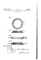
- FIG. 1 is a bottom plan view of a bungring, or fixture for the reception of a bung, in which the invention is embodied;
- Fig. 2 is a section projected from Fig. 1;
- Fig. 3 is an elevation showing the wall of a container as it is formed preparatory to reception of the bung ring, the wall being in section;
- Fig. 4 is an elevation showing the bung ring and the container wall after having been primarilysed in place, the view being in section;
- Fig. 5 is a fragmentary top plan view of the bung fixture in place.
- a bung ring 1 consisting of an internally threaded sleeve 2 having at one end thereof an external preferably formed of sheet metal.
- the sleeve has thereln drain openings 4, and the flange 3 is initially formed with an annular arched rib 5, and the outer marginal edge thereof is serrated.
- the wall 6 of the sheet metal container has an opening 7 made therein, and that portion of the wall surrounding the opening is pressed so as to form annular embossments 8 and 9 that project oppositely respecting the general plane of the wall, and the embossment 8 includes an internal flange 10 that encompasses the opening 7
- the ring is applied to the wall thus formed by inserting the flange of the ring 3 into the embossment 8 against the flange 10 with the sleeve projecting brave the embossmcnt 9 concentrically.
- ressure is then applied by means of suitable tools (not shown) to the rib 5 and to the embossment 9 whereupon the rib is flattened out so that the flange 3 is straightened into a flat plane and thereby extended outwardly against the wall 11 of the embossment 8, causing the wall to become also extended outwardly beneath the embossment 9, and the embossment 9 is pressed. downwardly and folded upon the face of the flange 3 opposite the flange 10 of the wall, thus confining the ring flange within the embossment 8.
- the invention is utilized in connection with a hung for sealing the opening 7 in the container, the bung being omitted from the drawings as any suitable type of bung may be employed.
- the ring constitutes an immovable fixture in the wall of the container for the reception of the bung for closing the opening therein, and the flange 10 of said wall provides an annular gasket seat for the bung.
- a bung fixture for a metal container consisting of a ring having an internally threaded sleeve provided at one end thereof with a serrated external flange that has formed therein an arched rib encompassing the sleeve whereby the outer circumference, upon flattening of said rib, may be enlarged.
- a bung fixture for a metal container having a wall with an openingtherein and provided with contiguous annular embossments oppositely disposed respecting said wall which fixture consists of a ring having an internally threaded sleeve provided at one end with an external annular flange having an arched annular rib whereby when the flange of said ring is positioned within said enibossments, and said rib and 'embossments are flattened, the said flange becomes circumferentially enlarged and secured in said embossments.
- a bung fixture for a metal container having a wall with an opening therein provided with an annular compressible embossment and contiguous flange surrounding said opening which fixture consists of an internally threaded ring provided at one end thereof with an external radially disposed flange having formed therein a compressible annular arched rib whereby, when the flange of said ring is positioned within said embossment, and said rib and embossment are compressed, said ring is permanently secured to the wall of the container concentrically with the opening therein.
Landscapes
- Engineering & Computer Science (AREA)
- Mechanical Engineering (AREA)
- Closures For Containers (AREA)
Description
March ZQ, 1932. T, w RlEKE 1,851,938
BUNG FIXTURE FOP SHEET METAL CONTAINERS AND METHOD OF ATTACHINGTHE SAME Filed May 9. 1929 flw lfiz/- INVENTOR.
BY %%MM4TTORNEY.
Patented Mar. 29, 1932 THEODORE W. RIEKE, J3 AUBURN, INDIANA,
ASSIGNOB TO RIEKE METAL PRODUCTS CORPORATION, A CORPORATION OF INDIANA BUNG FIXTURE FOB SHEET METAL CONTAINERS AND. METHOD OF ATTACHING THE SAME Application filed Kay 9, 1929. Serial No. 361,687.
This invention relates to improvements in bung fixtures for sheet metal containers, and the method of applying same. The object of the invention is to so construct the fixture l, and form the wall of the container as will admit of clinching the fixture permanently in the wall by a single and simple operation. Another object of the invention is to provide a bun ring with a flange so constructed, and
10. to so orm the wall of a metal container that 16 of providing a flange 3, is
said flange when applied to the wall is clinched in place therein and held from rotation relative thereto, and a further object is to afford a simple and inexpensive method sheet metal container with a bun fixture for the reception of a hung.
These objects are accomplished by the construction illustrated in the accompanying drawings, in which Fig. 1 is a bottom plan view of a bungring, or fixture for the reception of a bung, in which the invention is embodied;
Fig. 2 is a section projected from Fig. 1;
Fig. 3 is an elevation showing the wall of a container as it is formed preparatory to reception of the bung ring, the wall being in section;
Fig. 4 is an elevation showing the bung ring and the container wall after having been preissed in place, the view being in section; an
Fig. 5 is a fragmentary top plan view of the bung fixture in place.
In carrying out the invention, a bung ring 1 consisting of an internally threaded sleeve 2 having at one end thereof an external preferably formed of sheet metal. The sleeve has thereln drain openings 4, and the flange 3 is initially formed with an annular arched rib 5, and the outer marginal edge thereof is serrated.
The wall 6 of the sheet metal container has an opening 7 made therein, and that portion of the wall surrounding the opening is pressed so as to form annular embossments 8 and 9 that project oppositely respecting the general plane of the wall, and the embossment 8 includes an internal flange 10 that encompasses the opening 7 The ring is applied to the wall thus formed by inserting the flange of the ring 3 into the embossment 8 against the flange 10 with the sleeve projectingjahrough the embossmcnt 9 concentrically. ressure is then applied by means of suitable tools (not shown) to the rib 5 and to the embossment 9 whereupon the rib is flattened out so that the flange 3 is straightened into a flat plane and thereby extended outwardly against the wall 11 of the embossment 8, causing the wall to become also extended outwardly beneath the embossment 9, and the embossment 9 is pressed. downwardly and folded upon the face of the flange 3 opposite the flange 10 of the wall, thus confining the ring flange within the embossment 8. Owing to the pressure of the projections 12 of the serrated perimeter of the flange 3 against the wall 11 of the embossment 8, when the ring is pressed into place, the wall is caused to conform to the form of the serrated perimeter of the flange 3, whereby relative turning movement of the ring in the wall of the container is prevented.
The invention is utilized in connection with a hung for sealing the opening 7 in the container, the bung being omitted from the drawings as any suitable type of bung may be employed.
The ring constitutes an immovable fixture in the wall of the container for the reception of the bung for closing the opening therein, and the flange 10 of said wall provides an annular gasket seat for the bung.
What I claim is 1. A bung fixture for a metal container, consisting of a ring having an internally threaded sleeve provided at one end thereof with a serrated external flange that has formed therein an arched rib encompassing the sleeve whereby the outer circumference, upon flattening of said rib, may be enlarged.
2. The method of securing a flanged bung ring in the wall of a metal sheet container. consisting of forming in that portion of said wall surrounding its bung opening, oppositely projecting annular embossments contiguous with each other; forming an annular arched rib in the flange of said bung ring; inserting said flange into place between said embossments concentric with respect to said 100 opening; and applying pressure to said rib and to said embossments whereby the rib is flattened and the outer circumference thereof is enlarged, and one of said embossments is folded over the rear face of said flange.
3. A blmg fixture for a metal container having a wall provided with an opening and formed with two annular embossments disposed around said opening and that project oppositely respecting the general plane of the wall, one of which embosslnents includes an internal flange encompassing the opening and forms a gasket seat, which fixture consists of a ring having an internally threaded sleeve provided at one end thereof with a serrated annular flange that has formed therein an arched annular rib whereby the outer circumference of said flange is adapted to be enlarged upon flattening of said rib so as to be secured to the wall of the container axially alined with the opening therein when said rib and embossments are compressed.
4. A bung fixture for a metal container having a wall with an openingtherein and provided with contiguous annular embossments oppositely disposed respecting said wall, which fixture consists of a ring having an internally threaded sleeve provided at one end with an external annular flange having an arched annular rib whereby when the flange of said ring is positioned within said enibossments, and said rib and 'embossments are flattened, the said flange becomes circumferentially enlarged and secured in said embossments.
' 5. A bung fixture for a metal container having a wall with an opening therein provided with an annular compressible embossment and contiguous flange surrounding said opening, which fixture consists of an internally threaded ring provided at one end thereof with an external radially disposed flange having formed therein a compressible annular arched rib whereby, when the flange of said ring is positioned within said embossment, and said rib and embossment are compressed, said ring is permanently secured to the wall of the container concentrically with the opening therein.
In testimony-whereof I aflix my signature.
THEODORE W. RIEKE.
Priority Applications (1)
| Application Number | Priority Date | Filing Date | Title |
|---|---|---|---|
| US361687A US1851938A (en) | 1929-05-09 | 1929-05-09 | Bung fixture for sheet metal containers and method of attaching the same |
Applications Claiming Priority (1)
| Application Number | Priority Date | Filing Date | Title |
|---|---|---|---|
| US361687A US1851938A (en) | 1929-05-09 | 1929-05-09 | Bung fixture for sheet metal containers and method of attaching the same |
Publications (1)
| Publication Number | Publication Date |
|---|---|
| US1851938A true US1851938A (en) | 1932-03-29 |
Family
ID=23423063
Family Applications (1)
| Application Number | Title | Priority Date | Filing Date |
|---|---|---|---|
| US361687A Expired - Lifetime US1851938A (en) | 1929-05-09 | 1929-05-09 | Bung fixture for sheet metal containers and method of attaching the same |
Country Status (1)
| Country | Link |
|---|---|
| US (1) | US1851938A (en) |
Cited By (21)
| Publication number | Priority date | Publication date | Assignee | Title |
|---|---|---|---|---|
| US2866582A (en) * | 1955-12-13 | 1958-12-30 | Continental Can Co | Can end and nozzle assembly and method of producing same |
| US2889968A (en) * | 1954-07-13 | 1959-06-09 | Continenial Can Company Inc | Metallic receptacle spout or nozzle mounting and method of forming same |
| US2905124A (en) * | 1955-09-26 | 1959-09-22 | Continental Can Co | Method of attaching a bail ear |
| US2936928A (en) * | 1955-09-26 | 1960-05-17 | Continental Can Co | Bail ear and body blank assembly |
| US2975744A (en) * | 1956-02-17 | 1961-03-21 | Lyon George Albert | Method of and means for making wheel covers |
| US3374014A (en) * | 1965-07-27 | 1968-03-19 | Standard Pressed Steel Co | Swaged seals |
| US3457958A (en) * | 1965-04-26 | 1969-07-29 | Stereo Dishwashing Machine Mfg | Cleanout and sealing cap |
| US3747962A (en) * | 1972-05-05 | 1973-07-24 | Rieke Corp | Plastic closure-receiver for metal container |
| US3791021A (en) * | 1972-04-13 | 1974-02-12 | Ricke Corp | Method for installation of plastic closure receiver on metal container |
| US4195750A (en) * | 1977-09-29 | 1980-04-01 | Rieke Corporation | Molded flange for drums or other containers |
| US4743374A (en) * | 1986-03-14 | 1988-05-10 | Donaldson Company, Inc. | High-strength filter with improved fatigue rating |
| US5080787A (en) * | 1989-11-02 | 1992-01-14 | Fleetguard, Inc. | High-pressure filter assembly, method and apparatus for forming high-pressure filters |
| US5104537A (en) * | 1990-07-20 | 1992-04-14 | Donaldson Company, Inc. | High pressure hydraulic spin-on filter |
| US5601170A (en) * | 1993-11-09 | 1997-02-11 | Behr Gmbh & Co. | Fluid friction coupling |
| EP0779960A4 (en) * | 1994-09-08 | 2000-03-22 | Robertshaw Controls Co | Fuel control device, parts therefor and methods of making the same |
| US6328883B1 (en) | 2000-05-31 | 2001-12-11 | Parker-Hannifin Corporation | Fuel filter assembly with priming pump |
| US20050269329A1 (en) * | 2004-06-08 | 2005-12-08 | Baughman Gary M | Closure assembly for a container |
| US20050269330A1 (en) * | 2004-06-08 | 2005-12-08 | Baughman Gary M | Closure assembly for a container |
| USD533329S1 (en) * | 2004-10-22 | 2006-12-05 | Rieke Corporation | Threaded flange for installation into a container head |
| USD539005S1 (en) * | 2004-06-08 | 2007-03-20 | Rieke Corporation | Closing plug for a container-installed flange |
| US20140083922A1 (en) * | 2012-09-27 | 2014-03-27 | Cummins Filtration Ip, Inc. | Anti-rotation knurls |
-
1929
- 1929-05-09 US US361687A patent/US1851938A/en not_active Expired - Lifetime
Cited By (29)
| Publication number | Priority date | Publication date | Assignee | Title |
|---|---|---|---|---|
| US2889968A (en) * | 1954-07-13 | 1959-06-09 | Continenial Can Company Inc | Metallic receptacle spout or nozzle mounting and method of forming same |
| US2905124A (en) * | 1955-09-26 | 1959-09-22 | Continental Can Co | Method of attaching a bail ear |
| US2936928A (en) * | 1955-09-26 | 1960-05-17 | Continental Can Co | Bail ear and body blank assembly |
| US2866582A (en) * | 1955-12-13 | 1958-12-30 | Continental Can Co | Can end and nozzle assembly and method of producing same |
| US2975744A (en) * | 1956-02-17 | 1961-03-21 | Lyon George Albert | Method of and means for making wheel covers |
| US3457958A (en) * | 1965-04-26 | 1969-07-29 | Stereo Dishwashing Machine Mfg | Cleanout and sealing cap |
| US3374014A (en) * | 1965-07-27 | 1968-03-19 | Standard Pressed Steel Co | Swaged seals |
| US3791021A (en) * | 1972-04-13 | 1974-02-12 | Ricke Corp | Method for installation of plastic closure receiver on metal container |
| US3747962A (en) * | 1972-05-05 | 1973-07-24 | Rieke Corp | Plastic closure-receiver for metal container |
| US4195750A (en) * | 1977-09-29 | 1980-04-01 | Rieke Corporation | Molded flange for drums or other containers |
| US4743374A (en) * | 1986-03-14 | 1988-05-10 | Donaldson Company, Inc. | High-strength filter with improved fatigue rating |
| US5080787A (en) * | 1989-11-02 | 1992-01-14 | Fleetguard, Inc. | High-pressure filter assembly, method and apparatus for forming high-pressure filters |
| US5104537A (en) * | 1990-07-20 | 1992-04-14 | Donaldson Company, Inc. | High pressure hydraulic spin-on filter |
| US5601170A (en) * | 1993-11-09 | 1997-02-11 | Behr Gmbh & Co. | Fluid friction coupling |
| EP0779960A4 (en) * | 1994-09-08 | 2000-03-22 | Robertshaw Controls Co | Fuel control device, parts therefor and methods of making the same |
| US6328883B1 (en) | 2000-05-31 | 2001-12-11 | Parker-Hannifin Corporation | Fuel filter assembly with priming pump |
| US7520403B2 (en) | 2004-06-08 | 2009-04-21 | Rieke Corporation | Closure assembly for a container |
| US20050269330A1 (en) * | 2004-06-08 | 2005-12-08 | Baughman Gary M | Closure assembly for a container |
| US20060278644A1 (en) * | 2004-06-08 | 2006-12-14 | Rieke Corporation | Closure assembly for a container |
| USD539005S1 (en) * | 2004-06-08 | 2007-03-20 | Rieke Corporation | Closing plug for a container-installed flange |
| US7464830B2 (en) | 2004-06-08 | 2008-12-16 | Rieke Corproation | Closure assembly for a container |
| US7513387B2 (en) | 2004-06-08 | 2009-04-07 | Rieke Corporation | Closure assembly for a container |
| US20090090691A1 (en) * | 2004-06-08 | 2009-04-09 | Baughman Gary M | Closure assembly for a container |
| US20050269329A1 (en) * | 2004-06-08 | 2005-12-08 | Baughman Gary M | Closure assembly for a container |
| US20110147384A1 (en) * | 2004-06-08 | 2011-06-23 | Baughman Gary M | Closure assembly for a container |
| US7997440B2 (en) | 2004-06-08 | 2011-08-16 | Rieke Corporation | Closure assembly for a container |
| US8695840B2 (en) | 2004-06-08 | 2014-04-15 | Rieke Corporation | Closure assembly for a container |
| USD533329S1 (en) * | 2004-10-22 | 2006-12-05 | Rieke Corporation | Threaded flange for installation into a container head |
| US20140083922A1 (en) * | 2012-09-27 | 2014-03-27 | Cummins Filtration Ip, Inc. | Anti-rotation knurls |
Similar Documents
| Publication | Publication Date | Title |
|---|---|---|
| US1851938A (en) | Bung fixture for sheet metal containers and method of attaching the same | |
| US2415609A (en) | Container | |
| US2265167A (en) | Container | |
| US1947425A (en) | Bung fixture for sheet metal containers | |
| US2100168A (en) | Barrel or drum flange unit | |
| US1838285A (en) | Bung for containers | |
| US3098579A (en) | Closure reconditioning means and methods | |
| US3341107A (en) | Rim device for containers | |
| US3075676A (en) | Container spout | |
| US1783927A (en) | Bung fixture for sheet-metal containers | |
| US2866581A (en) | Plastic nozzle or spout mounting and method of forming same | |
| US1773947A (en) | Container | |
| US2021176A (en) | Repair plug | |
| US1891033A (en) | Sealing cap for the plugs of metallic drums and the like | |
| US1976673A (en) | Method of attaching a closure to a container | |
| US1722256A (en) | Bung sput and method of attaching the same to container walls | |
| US2085950A (en) | Container and closure means therefor | |
| US1930101A (en) | Socketed wall | |
| US2037923A (en) | Method of closing metal containers | |
| US1748923A (en) | Fitting for containers | |
| US2158549A (en) | Container | |
| US1795489A (en) | Wire-edged container and closure therefor | |
| US2289193A (en) | Frozen vegetable box | |
| US1082892A (en) | Sealing device for cans, &c. | |
| US1901581A (en) | Closure for containers |