US1851858A - Apparatus for straightening curly hair - Google Patents
Apparatus for straightening curly hair Download PDFInfo
- Publication number
- US1851858A US1851858A US380666A US38066629A US1851858A US 1851858 A US1851858 A US 1851858A US 380666 A US380666 A US 380666A US 38066629 A US38066629 A US 38066629A US 1851858 A US1851858 A US 1851858A
- Authority
- US
- United States
- Prior art keywords
- hair
- roller
- clamp
- spring
- shaft
- Prior art date
- Legal status (The legal status is an assumption and is not a legal conclusion. Google has not performed a legal analysis and makes no representation as to the accuracy of the status listed.)
- Expired - Lifetime
Links
- 238000010438 heat treatment Methods 0.000 description 10
- 210000003128 head Anatomy 0.000 description 5
- 238000005096 rolling process Methods 0.000 description 4
- 230000001788 irregular Effects 0.000 description 3
- 239000006210 lotion Substances 0.000 description 3
- 238000005192 partition Methods 0.000 description 2
- 230000000630 rising effect Effects 0.000 description 2
- 150000001361 allenes Chemical class 0.000 description 1
- 239000002537 cosmetic Substances 0.000 description 1
- 230000001419 dependent effect Effects 0.000 description 1
- 238000001035 drying Methods 0.000 description 1
- 210000003414 extremity Anatomy 0.000 description 1
- 239000012530 fluid Substances 0.000 description 1
- 238000009413 insulation Methods 0.000 description 1
- 239000007788 liquid Substances 0.000 description 1
- 239000002184 metal Substances 0.000 description 1
- 238000013021 overheating Methods 0.000 description 1
- 210000004761 scalp Anatomy 0.000 description 1
- 210000003813 thumb Anatomy 0.000 description 1
Images

Classifications
-
- A—HUMAN NECESSITIES
- A45—HAND OR TRAVELLING ARTICLES
- A45D—HAIRDRESSING OR SHAVING EQUIPMENT; EQUIPMENT FOR COSMETICS OR COSMETIC TREATMENTS, e.g. FOR MANICURING OR PEDICURING
- A45D2/00—Hair-curling or hair-waving appliances ; Appliances for hair dressing treatment not otherwise provided for
- A45D2/001—Hair straightening appliances
Definitions
- Another object of the invention is to rovide a relatively simplel contrivance wliich may be applied to the head for clamping the hair near the head and drawing the ends of the hair taut and holding the same in such positionwhile applying heat'to the hair so that the hair will remain for an indefiniteI period in the stretched or drawn conditionl and with all of the waves or kinks removed.
- the invention also aims at the provision of a relatively simple device which may be easily and quickly applied to the head and whic may be adjusted without the exercise of any undue skill, and/the provision of a device which is so constructed that it Vmay be applied to the head in sections to clamp the hair, to
- a further object of the present invention is to provide a hair straightening device of this general character which is provided with a clamp for holding the hair near the head, and which is also provided with a tensioning device for engaging the cuterv free portions of the hair and drawing and holding the same yieldingly in taut position during the heating or further treatment of the hair.
- a still further object of the invention is to provide a tension device embodying the above l0-.enumerated characteristics, and which is adapted to receive the hair coiled there about and may be rolled on the device by hand and subsequently positioned in the frame .of the devlce, and which is provided with means for tensioning the portion about which the hair is coiled so that the hair will be maintained taut and yieldingly in stretched condition.
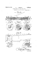
- Figure 1 is a longitudinal section taken through the device as applied to the hair, the section being taken vertically with respect to the position of the device in Figure 1.
- Figure 2 is a detail perspective view of the clamp or inner portion of the device.
- Figure 3 is a horizontal longitudinal section taken through the clamp or F i re 2, and showing the means or guiding an securlng together ⁇ the opposed members of the clamp.
- Figure 4 is a longitudinal section taken through the stretching and tensioning device for the hair.
- Figure 5 is a left hand end elevation of the same.
- Figure 6 is a transverse section taken 7 -7 of Figure 4 and looking in the direction of the arrows.
- Figure 8 is a detail perspective view of the heating section of the device.
- Figure 9 is a detail enlarged sectional view taken horizontally through one corner of the heating device, showing the yieldable securing means for holding the device in position,
- Figure 10 is a detail perspective view of a handle which may be employed for placing the spring of the tension device of Figure 4 under tension.
- the implement or device of this invention comprises three main parts: a clamp, atension device and a heater.
- the clamp part of the device comprises a pair of jaws 15 and 16, in the form of plates or blocks which are of suitable size and thickness and which are adapted to engage in edgewise relation forrclamping a quantity of hair between them.
- the abutting edge portions of the jaws and 16 are provided with interfitting irregular faces 17 to insure the proper alignment of the jaws 15 and 16 and to also provide an irregular path for securely clamping the hair between the jaws and holding the hair from slipping or pu lin through the clamp.
- the jaw 15 1s provide with a suitable number of dowels or guide pins 18 which are suitably mounted or formed upon the jaw 15 and which extend from the irregular face of the jaw and are adapted to enter openings formed throu h the opposite jaw 16, the pms 18 projecting eyond the jaw 16 and provided at one side with under cut teeth 19 which face inwardly toward the 'aw 15 and provide upon each pin 18 a rack.
- he outer portion of the jaw 16 is provided with a ratchet plate 2O which is mounted for longitudinal sliding movement upon the jaw 16 y means of screws 21 or the like which engage in slots 22 formed in the plate for limiting t e slidin movement of the plate 20 and to also hold t e same against the jaw 16.
- the plate 20 is provided with a long1tud1- ynally extending pin slot 23 adapted to register with a corresponding dowel pin 18 and through which the latter are adapted to project when the jaws 15 and 16 are brou ht together.
- the inner en ds of the guide s ots22 are each under cut to provide a tooth 24 at the inner end of each slot 22 disposed in align- ⁇ 'ment with the adjacent teeth 19 so that when 'the plate 20 is shifted in one direction all of the teeth 24 may interlock with the adjacent teeth 19 and thus hold the jaws 15 and 16 in clamping position".
- the plate 20 is preferably normally urged into clamping position by a spring 25 mounted in any suitable manner upon one end portion of the 'aw 16 and having a free end engaging the a jacent end of the late 20 so as to urge the latter into interloc 'ng engagement with the pins 18.
- the late 2O may also b e provided with a thum piece 26 011v one end and which projects outwardly from the plate for engagement by the thumb or linger for retracting the plate 2O when it is desired to open the clamp.
- the clamp is provided upon each end with a bracket 27 for supportingthe tension device and the heater upon the clamp when the three main parts o f the4 device are assembled.
- Each bracket 27 comprises a strip or plate of metal which extends across the jaws 15 and 16 at the upper sides of the latter, and the brackets 27 are secured at 28 by screws or the like to one of the jaws, such as the jaw 15 so that the jaw 16 may freely slide beneath the free end of the bracket 27.
- Each bracket 27 is provided intermediately with an upstanding arm 29, and one arm 29 is provided in its upper edge with a rounded recess or socket 30, while the other arm 29 1s provided with a non-circular socket or recess 31.
- Eachbracket plate 27 is also provid- Laagste ed near its opposite ends and at its outer edge portion with upstanding lugs or pro'ections 32 having relatively fiat and smoot inner faces an cylindrical depressionsor sockets 33 therein.
- the roller 34 is preferably hollow and a coil spring 35 may ⁇ be mounted in the roller 34, one end 36 secured to the roller 34 while the other end of the spring 35 is secured to a shaft 37 which extends axially in the roller 34.
- the shaft 37 is anchored at one end upon a stud or pin 38 swiveled to the shaft 37 and which is secured in the roller 34 by a screw 39 or the like. The shaft 37 is thus held in the roller 34 by the screw 39, and is free to turn upon the stud 38 so that the shaft 37 may be turned to place the spring 35 under the desired tens1on.
- the outer end ofthe shaft 37 is provided with a ratchet wheel 40 which co-operates with a, pawl 41 secured upon the outer end of the roller 34 as' shown in Fi ure 5 so as to interlock the ratchet 40 and t e shaft 37 to the roller 34.
- the outer extremity of the shaft 37 is provided with a ynon-circular shank or extension 42, and the-latter may be engaged by any suitable ⁇ tool or means for ⁇ the shaft.
- the shank or extension 42 is also constructed to seat in the non-circular socket 31 of the bracket- 27 for holding the shaft 37 in fixed position when theroller 34 is freed by the pawl 41.
- Roller 34 is provided with a trunnion or pin 46 adapted to seat in the socket 30 of the other bracket 27.
- the end portions 42 and 46 of the roller may also be employed for holding the roller and turning it bodily when wrapping the free ends'of the hair there about and also for positioning the roller in the sockets of the bracket 27.
- the roller 34 is-provided in one side with a hinged clamping arm 47 which is counter sunk in the side of the roller 34 and extends lengthwise thereof and which is adaptedto engage the free end portions of the hair and portion of the roller 34 and which is formed with its ends spaced apart to rovide a gap of suiicient width to admit o the swinging of the free end of the clamping arm 47 into and out of closed position.
- a hinged clamping arm 47 which is counter sunk in the side of the roller 34 and extends lengthwise thereof and which is adaptedto engage the free end portions of the hair and portion of the roller 34 and which is formed with its ends spaced apart to rovide a gap of suiicient width to admit o the swinging of the free end of the clamping arm 47 into and out of closed position.
- the third portion 'of the device comprises f the heater, and this structure is shown to adopen at its bottom and adapted to be fitted downwardly over the roller 34 and its parts and is provided in its opposite ends with recesses or openinvs-51 of a size which is equal at least to the dxmensionsof the upstanding arm 29 and which is adapted to seat at its ends upon the bracket 27.
- the casing is also provided at opposite ends and at its corners with spring pressed studs or balls 52 which are seated in the end Walls of the casing 50 and project'there beyond for en agement in the depressions or sockets 33 o the upturned lugs 32.
- the balls 52 are uro'ed outwardly by springs 53 mounted in cylindrical boxes 54 or the like which are secured within the cornerportions of the casing 50.
- the casing 50 of the heater is provided in its top with a heating unit 55 comprising heating electricV coils or the like for raising the temperature of the air within the casing 50.
- a metallic partition 56 is Secured within the casing 50 and beneath the heating unit 55 to notonly house the same, but to conduct the heat to the space beneath the partition 56.
- the openings 51 in the opposite ends of the casin 50 provide for the gradual and controlled ow of air upwardly through the casing from the clamp so that the air w1ll not be entrapped within the casing, and to thus prevent the overheating or burning of the hair or part of the device.
- the heating unit 55 is of the electrical type, the unit may be connected to a pair of contacts 5,7 which project from one end of the casing for the reception of an electric cord or the like, not shown in the drawings, to supply current to the unit 55.
- the clamp is then applied to the hair close to the scalp and the hair is preferably spread out in ,as thin a layer as possible, as shown in Figure 1 and thenv held securely by the clamp.
- the roller 34 which comprises the tension device, is then secured to the free ends of the hair by means of the clamping arm 47.
- the roller 34 is then turned by hand to evenly and flatly wind the layer of hair about the roller, as shown in Figure 1.
- the spring 35 of the roller placed under the desired tension by turning the shaft 37 and locking the same thru the pawl 41. As the hair is rolled with the desired amount of tension upon the. roller 34, the roller is brought gradually into position over the clamp and is finally seated on the brackets of the clamp.
- the pawl 41 is now released and the spring 35 turns the roller to urge it in a direction to place the ends of the hair under tension so that the hair is drawn tightly between the clamp andthe roller.
- the hair is thus wound in a relatively thin layer and spread over the surface of the roller'and is also held evenly taut as the spring 35 exerts a yielding tension on the hair.
- the casing 50 is then applied by inserting the same downwardly over the roller 34 and within the bracket arms 29 so that the spring projections '52 of the casing 50 interlock with the lugs 32 of the brackets 27. and yieldingly hold the casing-50m position.
- the heatingunit 55 is now operated to heat the space within the I f' casing 50 so. thatthe hair is subjected to heat and the latter is distributed'evenly throughout the length of the roller and the hair drled in its taut condition.
- clamping jaws 15 and 16 may be forced together to a more or less extent dependent upon the thickness of the layer of the hair and the rack teeth 19 admit of the locking of the jaws 15 and 16 together in various adjusted without departing'from the spirit of the in- 20 operated rolling device.
- hair straightening device comprising a clamp for engagin the hair, a s ring operated rolling device or receiving t ereabout the hair and stretching the hair beyond thev clamp, means for connecting the spring operated rolling device to the clamp for yieldably maintaining the hair taut, and means detachably mounted on the clamp and enclosing the spring operated rolling device to heat the hair held while being stretched by the spring 3.
- a hair straightening device com rising a clamp for engaging the hair, a roller etachably mounted on the clamp and adapted to receive the free ends ofthe hair wound thereabout, spring means for urging the roller to turn in one direction to stretch the hair, and heating means adjacent the roller to heat the hair while stretched by said roller and spring means.
- a hair straightening device comprising a clamp for engaging the hair, a roller detachably mounted on the clamp and adapted to receive the free ends of the hair wound thereabout, spring means for urgin the roller to turn in one direction to stretc the hair, adjusting means for the spring means to vary the initialtension of the spring means, and heating means adjacent the roller to heat the lhair while stretched by-said roller and spring means.
- a tension device detachably mounted in the brackets and adapted to receive the free end lportions of hair thereabout and to draw the atter tight between the tension device and the blocks, and aheating section mounted upon the brackets and enclosing the ⁇ tension device to heat the hair while being held taut.
- a hair straightening device comprising a clamp adapted to engage against the opposite sides of a layer of hair, a roller detachably mounted on the clamp, spring means conlnected tothe roller for urging the same to turn in one direction, means for interlocking
Landscapes
- Hair Curling (AREA)
Description
March 29, 1932. H, 1 MARSHALL 1,851,858
32 29 y -L E 3 [32 www Q l ,Y I
?? www I TTTTTTTT s.
NNNNNNN R. H Lunnis T. Maria-l1 lMarch 29, 1932. H. 1 J.. MARSHALL 1,851,858
APPARATUS FOR STRAIGHTENING CUHLY HAIR y Original Filed July 24. 1929 2 Sheets-Sheet 2 INSULATION INVENTOR.
H. L. 01.115 1-Marshall ATTORNEYS.
Patente.; ii/1m29, 1932 UNITED STATES PATENT lOFI-ICE HAMILTON LOUIS J. MARSHALL, OF PEROTE, ALABAMA, ASSIGNOB TO MABSB-'ALLENE COSMETIC COMPANY, A CORPORATION OF DELAWARE APPARATUS FOR STRAIGHTENING CURLY Application led July 24, 1922, Serial No. 380,666. Renewed August 17, 1931.
5- tion of permanently straightening the hair,
or of straightening the hair so that it will remain in such condition for av relatively long period of time'.
Another object of the invention is to rovide a relatively simplel contrivance wliich may be applied to the head for clamping the hair near the head and drawing the ends of the hair taut and holding the same in such positionwhile applying heat'to the hair so that the hair will remain for an indefiniteI period in the stretched or drawn conditionl and with all of the waves or kinks removed.
The invention also aims at the provision of a relatively simple device which may be easily and quickly applied to the head and whic may be adjusted without the exercise of any undue skill, and/the provision of a device which is so constructed that it Vmay be applied to the head in sections to clamp the hair, to
draw thefsame taut, and to heat the hair, the
sections interfittin and .being relativel movable and separa 1e, and which, combine produce a relatively light and compact device. A further object of the present invention is to provide a hair straightening device of this general character which is provided with a clamp for holding the hair near the head, and which is also provided with a tensioning device for engaging the cuterv free portions of the hair and drawing and holding the same yieldingly in taut position during the heating or further treatment of the hair.
A still further object of the invention is to provide a tension device embodying the above l0-.enumerated characteristics, and which is adapted to receive the hair coiled there about and may be rolled on the device by hand and subsequently positioned in the frame .of the devlce, and which is provided with means for tensioning the portion about which the hair is coiled so that the hair will be maintained taut and yieldingly in stretched condition.
The above, and various other objects andy advantages of this invention will in part be described in, and in part be understood from, the following detailed description of the present preferred embodiment, the same being illustrated in the accompanying drawings, wherein:-
Figure 1 is a longitudinal section taken through the device as applied to the hair, the section being taken vertically with respect to the position of the device in Figure 1.
Figure 2 is a detail perspective view of the clamp or inner portion of the device.
Figure 3 is a horizontal longitudinal section taken through the clamp or F i re 2, and showing the means or guiding an securlng together` the opposed members of the clamp. Y
Figure 4 is a longitudinal section taken through the stretching and tensioning device for the hair.
Figure 5 is a left hand end elevation of the same.
Figure 6 is a transverse section taken 7 -7 of Figure 4 and looking in the direction of the arrows.
Figure 8 is a detail perspective view of the heating section of the device.
Figure 9 is a detail enlarged sectional view taken horizontally through one corner of the heating device, showing the yieldable securing means for holding the device in position,
and
Figure 10 is a detail perspective view of a handle which may be employed for placing the spring of the tension device of Figure 4 under tension.
The implement or device of this invention comprises three main parts: a clamp, atension device and a heater. i
Referring now to the drawings, and rst to Figures 1, 2 and 3, the clamp part of the device comprises a pair of jaws 15 and 16, in the form of plates or blocks which are of suitable size and thickness and which are adapted to engage in edgewise relation forrclamping a quantity of hair between them. As shown particularly in Figure 2, the abutting edge portions of the jaws and 16 are provided with interfitting irregular faces 17 to insure the proper alignment of the jaws 15 and 16 and to also provide an irregular path for securely clamping the hair between the jaws and holding the hair from slipping or pu lin through the clamp. The jaw 15 1s provide with a suitable number of dowels or guide pins 18 which are suitably mounted or formed upon the jaw 15 and which extend from the irregular face of the jaw and are adapted to enter openings formed throu h the opposite jaw 16, the pms 18 projecting eyond the jaw 16 and provided at one side with under cut teeth 19 which face inwardly toward the 'aw 15 and provide upon each pin 18 a rack. he outer portion of the jaw 16 is provided with a ratchet plate 2O which is mounted for longitudinal sliding movement upon the jaw 16 y means of screws 21 or the like which engage in slots 22 formed in the plate for limiting t e slidin movement of the plate 20 and to also hold t e same against the jaw 16. o The plate 20 is provided with a long1tud1- ynally extending pin slot 23 adapted to register with a corresponding dowel pin 18 and through which the latter are adapted to project when the jaws 15 and 16 are brou ht together. The inner en ds of the guide s ots22 are each under cut to provide a tooth 24 at the inner end of each slot 22 disposed in align-` 'ment with the adjacent teeth 19 so that when 'the plate 20 is shifted in one direction all of the teeth 24 may interlock with the adjacent teeth 19 and thus hold the jaws 15 and 16 in clamping position". The plate 20 is preferably normally urged into clamping position by a spring 25 mounted in any suitable manner upon one end portion of the 'aw 16 and having a free end engaging the a jacent end of the late 20 so as to urge the latter into interloc 'ng engagement with the pins 18. The late 2O may also b e provided with a thum piece 26 011v one end and which projects outwardly from the plate for engagement by the thumb or linger for retracting the plate 2O when it is desired to open the clamp.
The clamp is provided upon each end with a bracket 27 for supportingthe tension device and the heater upon the clamp when the three main parts o f the4 device are assembled. Each bracket 27 comprises a strip or plate of metal which extends across the jaws 15 and 16 at the upper sides of the latter, and the brackets 27 are secured at 28 by screws or the like to one of the jaws, such as the jaw 15 so that the jaw 16 may freely slide beneath the free end of the bracket 27.
Each bracket 27 is provided intermediately with an upstanding arm 29, and one arm 29 is provided in its upper edge with a rounded recess or socket 30, while the other arm 29 1s provided with a non-circular socket or recess 31. Eachbracket plate 27 is also provid- Laagste ed near its opposite ends and at its outer edge portion with upstanding lugs or pro'ections 32 having relatively fiat and smoot inner faces an cylindrical depressionsor sockets 33 therein.
been secured in the clamp. The roller 34 is preferably hollow and a coil spring 35 may `be mounted in the roller 34, one end 36 secured to the roller 34 while the other end of the spring 35 is secured to a shaft 37 which extends axially in the roller 34. The shaft 37 is anchored at one end upon a stud or pin 38 swiveled to the shaft 37 and which is secured in the roller 34 by a screw 39 or the like. The shaft 37 is thus held in the roller 34 by the screw 39, and is free to turn upon the stud 38 so that the shaft 37 may be turned to place the spring 35 under the desired tens1on.
The outer end ofthe shaft 37 is provided with a ratchet wheel 40 which co-operates with a, pawl 41 secured upon the outer end of the roller 34 as' shown in Fi ure 5 so as to interlock the ratchet 40 and t e shaft 37 to the roller 34. The outer extremity of the shaft 37 is provided with a ynon-circular shank or extension 42, and the-latter may be engaged by any suitable `tool or means for` the shaft. The shank or extension 42 is also constructed to seat in the non-circular socket 31 of the bracket- 27 for holding the shaft 37 in fixed position when theroller 34 is freed by the pawl 41. Roller 34 is provided with a trunnion or pin 46 adapted to seat in the socket 30 of the other bracket 27. The end portions 42 and 46 of the roller may also be employed for holding the roller and turning it bodily when wrapping the free ends'of the hair there about and also for positioning the roller in the sockets of the bracket 27.
The roller 34 is-provided in one side with a hinged clamping arm 47 which is counter sunk in the side of the roller 34 and extends lengthwise thereof and which is adaptedto engage the free end portions of the hair and portion of the roller 34 and which is formed with its ends spaced apart to rovide a gap of suiicient width to admit o the swinging of the free end of the clamping arm 47 into and out of closed position.- In Fi ure 7 the locking ring 48 is shown in locke position and with one end ortion overlyin the arm 47 to hold it closed) in the roller. 'o release the arm 47 it is only necessary to slide the ring 48 circumferentlally in its groove 49 until the gap in the ring registers with the arm 47 when the latter may be easily raised.
The third portion 'of the device comprises f the heater, and this structure is shown to adopen at its bottom and adapted to be fitted downwardly over the roller 34 and its parts and is provided in its opposite ends with recesses or openinvs-51 of a size which is equal at least to the dxmensionsof the upstanding arm 29 and which is adapted to seat at its ends upon the bracket 27. The casing is also provided at opposite ends and at its corners with spring pressed studs or balls 52 which are seated in the end Walls of the casing 50 and project'there beyond for en agement in the depressions or sockets 33 o the upturned lugs 32.
The balls 52 are uro'ed outwardly by springs 53 mounted in cylindrical boxes 54 or the like which are secured within the cornerportions of the casing 50. The casing 50 of the heater is provided in its top with a heating unit 55 comprising heating electricV coils or the like for raising the temperature of the air within the casing 50. A metallic partition 56 is Secured within the casing 50 and beneath the heating unit 55 to notonly house the same, but to conduct the heat to the space beneath the partition 56. The openings 51 in the opposite ends of the casin 50 provide for the gradual and controlled ow of air upwardly through the casing from the clamp so that the air w1ll not be entrapped within the casing, and to thus prevent the overheating or burning of the hair or part of the device. When the heating unit 55 is of the electrical type, the unit may be connected to a pair of contacts 5,7 which project from one end of the casing for the reception of an electric cord or the like, not shown in the drawings, to supply current to the unit 55. j
It is thought that the use of the device will be apparent from the above description of the various parts thereof, but it may be briefiy pointed out that the operation or mode of use is as follows g It is found advantageous with the use of these devices to first treat the hair with a liquid to soften it so that the hair may be changed as to its shape during the drying process. In the present instance it is found morev practical and advantageous to use an alkaline lotion because it is found that this lotion penetrates to a greater extent than the ordinary permanent waving fluid now on the market.
After the hair has been dampened with the alkaline lotion the clampis then applied to the hair close to the scalp and the hair is preferably spread out in ,as thin a layer as possible, as shown in Figure 1 and thenv held securely by the clamp. The roller 34, which comprises the tension device, is then secured to the free ends of the hair by means of the clamping arm 47. The roller 34 is then turned by hand to evenly and flatly wind the layer of hair about the roller, as shown in Figure 1. The spring 35 of the rolleris placed under the desired tension by turning the shaft 37 and locking the same thru the pawl 41. As the hair is rolled with the desired amount of tension upon the. roller 34, the roller is brought gradually into position over the clamp and is finally seated on the brackets of the clamp. The pawl 41 is now released and the spring 35 turns the roller to urge it in a direction to place the ends of the hair under tension so that the hair is drawn tightly between the clamp andthe roller. The hair is thus wound in a relatively thin layer and spread over the surface of the roller'and is also held evenly taut as the spring 35 exerts a yielding tension on the hair. When the hair is thus placed in the device, the casing 50 is then applied by inserting the same downwardly over the roller 34 and within the bracket arms 29 so that the spring projections '52 of the casing 50 interlock with the lugs 32 of the brackets 27. and yieldingly hold the casing-50m position. The heatingunit 55 is now operated to heat the space within the I f' casing 50 so. thatthe hair is subjected to heat and the latter is distributed'evenly throughout the length of the roller and the hair drled in its taut condition.
The clamping jaws 15 and 16 may be forced together to a more or less extent dependent upon the thickness of the layer of the hair and the rack teeth 19 admit of the locking of the jaws 15 and 16 together in various adjusted without departing'from the spirit of the in- 20 operated rolling device.
spring. l
2. hair straightening device, comprising a clamp for engagin the hair, a s ring operated rolling device or receiving t ereabout the hair and stretching the hair beyond thev clamp, means for connecting the spring operated rolling device to the clamp for yieldably maintaining the hair taut, and means detachably mounted on the clamp and enclosing the spring operated rolling device to heat the hair held while being stretched by the spring 3. A hair straightening device, com rising a clamp for engaging the hair, a roller etachably mounted on the clamp and adapted to receive the free ends ofthe hair wound thereabout, spring means for urging the roller to turn in one direction to stretch the hair, and heating means adjacent the roller to heat the hair while stretched by said roller and spring means.
4. A hair straightening device, comprising a clamp for engaging the hair, a roller detachably mounted on the clamp and adapted to receive the free ends of the hair wound thereabout, spring means for urgin the roller to turn in one direction to stretc the hair, adjusting means for the spring means to vary the initialtension of the spring means, and heating means adjacent the roller to heat the lhair while stretched by-said roller and spring means.`
5'. Aphair straightening device, com rising.
a pair of clamping jaws, pins carried y one clamping jaw for slidable engagement through the opposite clamping jaw, aspring pressed locking plate carried bythe second aw, said pins having rack teeth `clamping thereon a apted for engagement with said ,mounted in the roller, a spring on the shaft secured at one end thereto, the other end of said spring being secured to said roller, means for turning said shaft to place the spring under tension, a ratchet wheel on said shaft, a pawl carried by the roller for engagement with theratchet wheel to lock the same when the spring is undertension, said shaft having a non-circular portion for engagement in interlocking relation with the other brackets to hold the shaft from turning relatively to the bracket, said pawl adapted to be released for turning the roller under tension of .said spring, a clamping arm mounted on the roller for engaging the free end portions of hair extending from the clamp, said roller adapted to be manually wound to spread the free end portions of the hair thereabout and to be subsequently seated in said brackets, said shaft being turned to exert the-desired tension on the spring whereby to draw said hair taut from the brackets under the desired tension, and'heating means enclosing said roller and seated on said clamp.
HAMILTON LOUIS J. MARSHALL.
locking plate upon the movement of said 4 jaws toward each other to lockthe clamp upon hairinterposed between the blocks, a pair of brackets carried by one of thedglocks, y
a tension device detachably mounted in the brackets and adapted to receive the free end lportions of hair thereabout and to draw the atter tight between the tension device and the blocks, and aheating section mounted upon the brackets and enclosing the `tension device to heat the hair while being held taut.
6. A hair straightening device, comprising a clamp adapted to engage against the opposite sides of a layer of hair, a roller detachably mounted on the clamp, spring means conlnected tothe roller for urging the same to turn in one direction, means for interlocking
Priority Applications (1)
| Application Number | Priority Date | Filing Date | Title |
|---|---|---|---|
| US380666A US1851858A (en) | 1929-07-24 | 1929-07-24 | Apparatus for straightening curly hair |
Applications Claiming Priority (1)
| Application Number | Priority Date | Filing Date | Title |
|---|---|---|---|
| US380666A US1851858A (en) | 1929-07-24 | 1929-07-24 | Apparatus for straightening curly hair |
Publications (1)
| Publication Number | Publication Date |
|---|---|
| US1851858A true US1851858A (en) | 1932-03-29 |
Family
ID=23502032
Family Applications (1)
| Application Number | Title | Priority Date | Filing Date |
|---|---|---|---|
| US380666A Expired - Lifetime US1851858A (en) | 1929-07-24 | 1929-07-24 | Apparatus for straightening curly hair |
Country Status (1)
| Country | Link |
|---|---|
| US (1) | US1851858A (en) |
-
1929
- 1929-07-24 US US380666A patent/US1851858A/en not_active Expired - Lifetime
Similar Documents
| Publication | Publication Date | Title |
|---|---|---|
| US1455696A (en) | Electric oven for hair | |
| US2720207A (en) | Hair curler and applicator therefor | |
| US20140353301A1 (en) | Hair styling appliance | |
| US2805436A (en) | Paint applicator | |
| US1851858A (en) | Apparatus for straightening curly hair | |
| US2910988A (en) | Hair straightening device | |
| TWM537426U (en) | Wave perm device | |
| US1718025A (en) | Hair-ctrrling | |
| US2035815A (en) | Hair waving apparatus | |
| US2051579A (en) | Appliance for waving hair | |
| US2403350A (en) | Hair treating machine | |
| US1939323A (en) | Method of and appliance for waving hair | |
| US2392157A (en) | Apparatus for waving hair | |
| US1678890A (en) | Marcelling and permanent-wave irons | |
| US1756837A (en) | Hair-waving equipment | |
| US2721560A (en) | Hair waving rod | |
| US2003811A (en) | Hair waving device | |
| US2048934A (en) | Hair waving apparatus | |
| US2083823A (en) | Apparatus for waving hair | |
| US1665253A (en) | Permanent-wave apparatus | |
| US2183023A (en) | Permanent waving apparatus | |
| US1903743A (en) | Apparatus for hair waving | |
| US1957046A (en) | Apparatus for waving hair | |
| US2584434A (en) | Hair straightening machine | |
| US2108374A (en) | Permanent wave curler |