US1851838A - Tape reperforator - Google Patents
Tape reperforator Download PDFInfo
- Publication number
- US1851838A US1851838A US468921A US46892130A US1851838A US 1851838 A US1851838 A US 1851838A US 468921 A US468921 A US 468921A US 46892130 A US46892130 A US 46892130A US 1851838 A US1851838 A US 1851838A
- Authority
- US
- United States
- Prior art keywords
- tape
- selecting
- perforator
- feed
- punch
- Prior art date
- Legal status (The legal status is an assumption and is not a legal conclusion. Google has not performed a legal analysis and makes no representation as to the accuracy of the status listed.)
- Expired - Lifetime
Links
- 230000007246 mechanism Effects 0.000 description 119
- 238000009877 rendering Methods 0.000 description 11
- 210000002105 tongue Anatomy 0.000 description 10
- 238000004804 winding Methods 0.000 description 10
- 239000004020 conductor Substances 0.000 description 6
- 239000011435 rock Substances 0.000 description 3
- 230000000694 effects Effects 0.000 description 2
- 238000005192 partition Methods 0.000 description 2
- 230000005540 biological transmission Effects 0.000 description 1
- 230000006835 compression Effects 0.000 description 1
- 238000007906 compression Methods 0.000 description 1
- 238000010276 construction Methods 0.000 description 1
- 230000004048 modification Effects 0.000 description 1
- 238000012986 modification Methods 0.000 description 1
- 230000035772 mutation Effects 0.000 description 1
- 230000000284 resting effect Effects 0.000 description 1
- 230000000717 retained effect Effects 0.000 description 1
- 230000008054 signal transmission Effects 0.000 description 1
- 239000007787 solid Substances 0.000 description 1
Images


Classifications
-
- H—ELECTRICITY
- H04—ELECTRIC COMMUNICATION TECHNIQUE
- H04L—TRANSMISSION OF DIGITAL INFORMATION, e.g. TELEGRAPHIC COMMUNICATION
- H04L17/00—Apparatus or local circuits for transmitting or receiving codes wherein each character is represented by the same number of equal-length code elements, e.g. Baudot code
- H04L17/16—Apparatus or circuits at the receiving end
- H04L17/20—Apparatus or circuits at the receiving end using perforating recorders
Definitions
- This invention relates to a tape perforator for use in connection with a telegraph transmitter and more particularly to the control ofthe feeding of the tape through the perforator.
- the present invention relates to a reperforator responding to line signals of the Baudot type, that is, to signals consisting of permutations of a uniform number of marking and spacing conditions, received over a multiplex channel for producing a perforated tape for use in retransmission over another circuit through a tape transmitter. It is desirable, of course, to have as short a time lag as possible between the perforating of the tape and the retransmission of the signals.
- the minimum lag between the reception of the signals and the retransmission thereof may be considerable, and in order to prevent further delay, by the tape between the perforator and the tape transmitter, upon temporary cessation of the transmission of signals, it has been proposed heretofore to feed the tape continuously through the perforatur during such idle periods of the cha. ..l of the receiving circuit associated with the perforator.
- the present invention has for one of its objects to render such continuous tape feeding mechanism inoperative after-a predetermined maximum length of tape has been advanced through the perforator.
- Another object is to provide a control mechanism for causing the tape to be advanced through the perforator, upon cessation of the received signals, a sufficient distance to bring the last signal perforation into operating position in the tape transmitter.
- Another object is to start said control forator employing agroup of selecting mag-- nets, corresponding to the units of the per-- mutation telegraph code, the magnets being locked up in accordance with each received. code signal, through abank of relays having their windings associated with the contacts of the receiving rotary distributor.
- the selecting magnets effect the selection of the punch pins to be operated.
- a punch solenoid is controlled through the segments of the local distributing ring to operate the punch pins, and through a paper feed mechanism to advance the tape into the succeeding perforating position.
- the punch solenoid actuated once each revolution of the receiving distributor brushes, irrespective of whether sig-., nals are being received, and therefore advances the tape continuously through the perforator during idle periods of the channel.
- a counting or feed control mechanism driven by the tape feed mechanism and having a predetermined maximum extent of travel, in the extreme limit of which it renders the tape feed mechanism inoperative.
- the feed control mechanism is brought into operative engagement with the tape feed mechanism after complet-' ing each perforating cycle of the machine, to permit the feed control mechanism to be driven by the tape feed mechanism, and it is removed from operative engagement therewith upon the reception of each group of code signals to permit the control mechanism to be returned to its initial or starting position. Therefore, thefeed control mechanism is in position, after each perforation has been completed, to permit a uniform maximum quantity of tape to be advanced through the perforator, in case no further signals are received.
- Figure 2 is a vertical sectional view on an enlarged scale of the perforator substantially on the line 22 of Figure 1;
- Figure 3 is a plan view of the reperforator
- Figure 4 is a rear elevational View of the tape feed control mechanism
- Figure 5 is a front elevation thereof in one position of operation
- Figure 6 is a front elevational view of the tape feed control mechanism in another posrtion of operation;
- Figure 7 is a detailof the rub out responsive mechanism for preventing operation of the punch solenoid on the reception of a rub out signal;
- Figure 8- is a diagrammatic view of the reperforator and the operating and control circuits therefor.
- the supporting structure for the reperforator comprises a base plate 10 and a vertical partition plate 11 carried thereby.
- the reperforating mechanism is supported on one srde of the plate 11 (on the lefthand side in Flgure 2), and the tape feed control mechanism 1s mounted upon the opposite side thereof.
- the reperforating mechanism consists in general of a punch block 12'mountedupon the plate 11 by a lug 13, and having a group of punch pins 14, a punch hammer 15 pivoted at 16, for operating the punch pins, a number of interponent bars 17 adapted to be shifted beneath the punch pins to determine the operation thereof, selecting solenoids 18 for actuating the interponent bars, punch solenoids 19 for operating the punch hammer 15 and a paper feed roller 20 actuated by the punch hammer 15 through a pawl 21.
- the tape 22 extends from a suitable reel 23 over a tensioning lever 24 pivoted at 25 and provided with a tensioning spring 26 ( Figure 5), and thenceacross the top of the punch block 12.
- the particular punch block illustrated is provided with punches of such number and arrangement as to adapt the perforator for use in perforating tape for automatic printing telegraph systems employing a code wherein each character comprises six impulses, although obviously the number of punches and number of units, of the code may tape.
- the form shown comprises seven punches 27, of which six are employed to punch the code"holes in the tape, and the seventh or central punch 27 is designed to form feed holesin the tape, this punch being of smaller diameter than the remaining punches.
- Each of the punches has an annul'ar enlargement or collar 28 normally resting on the lower wall of the punch block, the
- punches extending downwardly thfough the lower wall and upwardlythrough openings in a retracting plate 29 and through openings in the top wall of the punch block.
- the punches are retained in the lowered position by compression springs 30 surrounding certain of the punch pins.
- a die plate 31 is secured to the top of the punch block and is provided with openings in alignment with the punch pins.
- the top of the punch block I is grooved at 32 for the passage of the tape between the die plate and the top of the punch pins.
- the feed holes have to be punched for every character and also for .the blanl; por- K 35 adapted to be attracted by the selecting solenoids.
- the selecting solenoids are mounted uponja shelf 36 carried by the partition plate 11.
- the cores 39 and 40 of the punch solenoids 19 are secured to a cross bar 41 having a vertical push rod 42 bearing against the lower side of the hammer 15, to elevate the same against the tension of the retractile spring 43, to raise the interponent members,
- the hammer 15 directly engages the paper feed pin 27 to punch the feed hole.
- the feed roller 20 is jou'rnaled in a block 44 and in the plate 11, and is provided with a circumferential row of radial pms'45' which engage the control feed openings of the tape to draw the tape through the punch block.
- Ratchet teeth 46 are formed on the feed roller, against which the pawl 21 is held by a spring-47, the pawl being positioned in one of the ratchet teeth upon the upper movement of the hammer 15, and rotating the, feed wheel one space on the return ,movement of the hammer. reduced and extends through" the plate" '11.
- a star wheel 48 is attached to this extended end and a jockey roller 49 is held against the One end of the feed wheelisstar wheel by a spring 50 to accurately position the feed wheel after each movement thereof.
- the tape is held against the feed wheel and in engagement with the feed pins 45 by an eyelet 52 carried by aframe 53 pivoted on a shaft 54 and urged against the tape by a -lay is unconnected and the marking contact 722; is connected to ground G.
- the receiving rings of the distributor comprise a solid ring 62, connected to the tongue T of the receiving relay and a segmented ring 63, containing two sets of six segments each, for two channel multiplex'operation. The circuit connections for the first channel only are shown in this figure.
- Segments l to 6 of channel one are connected to one terminal of the windings'64 of the six selecting relays 65, 66, 67, 68, 69 and 70, the opposite terminals of which are connected, by a common conductor, to a source of potential 71.
- Each of the relays 65 to 70 have two contacttongues 72 and 73 and cooperating front contacts. Tongues 72 are joined through a common conductor 74 and the back contact and tongue 75 of a break relay 76, to the ground at G1.
- the front contacts of tongues 72 are connected to one terminal of the windings 64, to provide a locking circuit therefor.
- Tongues 7 3 of each of the relays 65 to 70 are connected by the common conductor to the source of potential 71, the front contact of each of these relays being connected, respectively, to one terminal of the selecting solenoids 1 to'6' of the reperforator.
- the opposite terminals of the selecting solenoids are connected b a common conductor 77 to the ground at '2.
- the local ring 58 comprises asolid ring ,78 grounded at G3 and a segmentedring 79 having twelve segments. Segment 9 is connected to one terminal of the winding of the relay 80, the opposite terminal ofwhich is connected to the source of potential 71 and segment 11 is connected to one terminal of the winding of the break relay 76, the opposite terminal being connected to the source of potential at 71.
- Relay 80 has a single contact tongue 81 connected to the source ofpotential 71 and a corresponding front contact, connected by conductor 82, to one end of the winding of a locking relay 83, the opposite end of which is grounded at G2.
- the front contact of relay '88 is connected through a resistance R to the relay winding and also directly through the winding of the punch solenoids 19'to the ground G2.
- Tongue 84 oflrelay 83 is connected through normally closed contacts 85, contacts 86 and contacts 87, to a source of potential 88.
- the contacts 86 are adapted to be openedon the upward movement of the plunger of the printing solenoid by an extension 89 carried by the cross bar 41 ( Figure 2).
- the receiving relay 56 will operate to apply the. ground G to the windings of the relays 65, 66 and 69, as the distributor brush B passes over receiving segments 1, 2 and 5, thus causing these relays to pick up and complete their I locking circuits through the tongues 72.
- the battery 71 is applied through the tongues 73 of relays 65, 66 and 69, to the selecting solenoids 1', 2', and 5' to shift the interponent bars of these magnets beneath the corresponding punch ins.
- the ground G3 is applied to the relay 80, which picks up and applies the battery 71, through .conductor 82, to the locking relay83 which is thus operated to complete the circuit for the punch solenoids 19, this circuit extending from the battery 88 through the contacts 87 86and andfront contact of the relay 83, thence through the punch solenoids and to ground G2.
- a locking circuit is established for the relay 83 fromthe tongue 84, through the resistance R to the relay winding and thence to the ground G2.
- the solenoids 19, effect the perforation of the tape in accordance with the setting ofit-he interponent bars 17, at the same time operatingthe tape feed mechanism through the pawl 21, to advance the tape into the succeeding perforating position.
- the contact 86 is opened to break the looking circuit for the relay 83.
- the break relay 7 6 Upon passage of the brush B across segment 11, the break relay 7 6 is operated to remove the ground G1 from the selecting relays 65 to 70, allowing them to return to normal and thus interrupting the circuits to the selecting solenoids 18, whereby the interponent bars are returned to normal position in readiness for the succeeding code signal.
- the relays 65 to' 70 remain unoperated. However, during each revolution of the brush B, the relay 80 operates to actuate the punch solenoids 19 and the tape feed mechanism, to advance the tape continuously through the perforator. Since the interponentbars 17 are not shifted during this operation, only the tape feed hole is punched.
- a stub shaft 92 secured to the pin plate 11, has a bushing 93 upon which a lever 94 is journaled.
- the lever carries a pinion 95 normally held in mesh with a small gear 96 mounted rigidly upon the extended end of the feed roller 20.
- a gear wheel 97 in mesh with the pinion 95, is journaled upon a bushing 98 fixed to the shaft 92.
- Bushing 98 terminates in a disc 99 spaced from the gear 97 and a spiral spring 100 is mounted between the disc and the gear wheel 97.
- the inner end of a 1 spring is anchored by a pin 101, carried by the disc and the outer end of the spring is secured to a pin .102 carried by the gear wheel.
- the gear wheel also carries a pin 103 near its outer edge which, when the gear is rotated sufii- 2o ciently, engages the inclined face 104 of a contact block 105, pivoted at 106, to depress the same against the tension of the spring 107,
- the lever 94 has a link 113 pivoted thereto and to the vertical arm of a-bell crank lever 114, pivoted at 115.
- the horizontal arm of the bell crank lever is connected by a link 116 to the horizontal arm of a second bell crank lever 117, by means of a pin 118, extending through an opening 119 in the plate 11.
- the vertical arm of the lever 117 comprises a bail having a horizontal portion 120extending v ment with the gear 96, the lever 94 being across the interponent bars 17 slightly thereabove and slightly in advance of projections 122 integral with the interponent bars, so, that when any one of the interponent bars is shifted, in response to a selecting cond tion, the bail is engaged by theprojection 122 to rock the lever 117 and thence to withdraw the pinion 95 from engagement with the gear 96, as shown in Figure 4.
- the horizontal arm of the bell crank lever 114 when elevated at this time, is locked in its upperposition by engagement of the end thereof with a shoulder .123, of a latch 124, pivoted at 125 and urged towards the bell crank lever by a spring 126.
- the latch 124 is arranged to be moved from a push rod 127, pivoted tothe latch and to the plate 11 through the pin and slot 128.
- wheel 97 in an inturned end 129 and is enengagement with the bell crank lever 114, by
- the operation of the tape feed control mechanism is as follows: Assume the distributor 57 to be rotating idly, that is without signals being transmitted over channel one, so that upon each revolution thereof the solenoid 19 operates to form a feed hole in the tape and to advance the tape through the perforator. Since none of the selecting magnets are energized, all of the interponent bars 17 are held in their normal position with the projections 122 out of contact with the bell crank lever,117, thus permitting the pinion '95 to be held in mesh with the gear 96, on the feed roller shaft.- Therefore, the gear wheel 97 is rotated from the position shown in Figure 5, to that shown in Figure 6, in a counterclockwise direction, to bring the pin 103 in engagement with the contact block 105, to open the contacts 85.
- the pin 103 may be provided at any point along the gear wheel so as to permit the tape to be fed forwardat anydesired number of spaces prior to the opening of the contacts 85 and should be positioned so as to permit a sufficient length of tape to be advanced after cessation of the code signals to bring the' last code signal perforation in operative position in the tape transmitter, which may be located adjacent to the perforator.
- the gear wheel 97 is maintained in the position shown in Figure 6 to hold the contacts 85 open until the next selecting signal is received, at which time one of the interponent bars will be shifted forward to rock the lever 94 and withdraw the pinion 95 from engagelocked in this position by the latch 124.
- the gear wheel 97 being thus released rides backwards in aclockwise. direction under the action of the spring 10.0 until the dog 130 strikes the inturned end of the lever 127 to trip the latch 124 and again permit the pinion 95 to move into engagement w'th the gear 96.
- v If no further code signals ai e received the previous cycle is repeated. However, if a succession of code signals are received the pinion 95 is moved out of engagement with the gear 96 for each new selecting condition, to permit the gear wheel to be reset in its initial position.
- the tape may be advanced through the perforator any number of spaces up to the predetermined 'maximum as determined by the counting or control mechanism and the control: mechanism will be set back to its initial position upon the receipt of the next code signal, from Whatever position it may be in.
- a rub-out signal consists of all marking impulses and is transmitted when the operator of the keyboard perforator at the transmitting station makes an error in perforating the tape. In such cases the tape is backed up through the keyboard perforator and reperforated with a complete row of openings.
- a rub-out signal is received all of the interponent bars move forward and out of contact with a second bell crank lever 132, having a bail normally engaged by the projections 122- The bell crank lever is thus free to rock under the action of the spring 133 to open contacts 87 and thus interrupt the circuit to the punch solenoid 19. This is desirable in order that the rub-out signals will not be reproduced in the reperforated tape.
- the locking relay 83 shown in Figure 8 is mounted upon the base plate 10 as shown in Figure 5.
- a perforatlng mechanism responsive to signals for the Baudot code for controlling said perforating mechanism, means for advancing the tape through the perforator one space for each selecting code combination applied to said selective mechanism, and means for automatically advancing the tape through the perforator a predetermined maximum number of spaces upon inaction of said selectng mechanism.
- a perforating mechanism a perforating mechanism, a selecting mechanism responsive to character code groups consisting of mixed marking and spacing conditions for controlling said perforating mechanism, a tape feed mechanism for advancing the tape through the perforator one space for each selecting group applied to the selecting mechanism,
- said tape feed mechanism automatically advancing the tape through the perforator upon inaction of said selecting mechanism and counting mechanism set into operation when a signal group consisting of spacing conditions only is applied tosaid selectmg mechanism, to discontinue the operation of the tape feed mechanism after the tape has advanced through the perforator a predetermined number of spaces.
- a perforating mechanism In a tape perforator, a perforating mechanism, a selecting mechanism controlling said perforating mechanism, and a tapeone space for each selecting group, said tape feed mechanism also advancing blank tape through the perforator for each non-selecting slgnal group, a counting mechanism for de. termining the length of blank tape advanced through the perforator, and means responsive to a marking condition in anysignal group for resetting said counting mechanism upon each operation of the selecting mechanism.
- a synchronously operating distributor a tape perforator, a perforating mechanism, a selecting mechanism controlled by said distributor for said perforating mechanism, a'tape feed mechanisnr controlled by said distributor for adv'anclng the tape through the perforator one space for each selecting condition
- said tape feed-mechanism also advancing blank tape through the perforator upon inaction of said selecting mechanism
- a counting mechanism for determining the length of blank tape advanced through the perforator, means for starting said counting mechanism into operation after each operation of the perforating mechanism, and means for restoring the same to its initial position-upon eachopera tion of the selecting mechanism.
- a perforating mechanism for continuously advancingtape through the perforating mechanism, counting means normally in engagement with said tape feed mechanism for discontinuing the operation thereof after a predeterm'ned length of tape has been advanced thro gh the perforating mechanism, and means operating upon the in one limit of movement thereof to discon tinue the operation of the tape feed mechanism, and means acting upon the reception of a marking condition in each selecting group for setting said first means in its otherlimit of movement.
- a perforating mechanism In atape reperforator, a perforating mechanism, a selecting mechanism responsive to received signals, a tape feed mechanism for continuously advancing tape through the perforating mechanism, means actingwhen no selecting conditions are set up for rendering said perforating and tape feed mechanism inoperative after a predetermined length of tapehas been advanced, and means responsive to a rub-out signal for rendering said perforating and tape feed mechanism immediately inoperative.
- a perforating mechanism a selecting mechanism responsive to received signals, a tape feed mechanism for continuously advancing tape through the perforating mechanism, means acting when no selecting conditions are set up for rendering said perforating and tape feed mechanism inoperative after a predetermined length of tape has been advanced, means for again rendering said perforating and tape feed mech anism operative upon setting up of a selecting condition and separate means for rendering the perforating and tape feed mechanism in operative while a rub-out selecting condition is set up.
- a perforating mechanism a perforating mechanism, a selecting mechanism responsive to received signals, a tape feed mechanism, a
- said element controlling said perforating and tape feed mechanism to continuously perforate feed holes and feed the tape through the per forating mechanism, a gear wheel, an intermediate pinion in mesh with said gear wheel, a gear driven by said tape feed mechanism, means for causing engagement of said pinion with said gear when the selecting mechanism is unoperated'and for causing disengagement thereof when said selecting mechanism is operated to set up a selecting condition, said gear wheel on predetermined rotation thereof rendering said perforating and tape feed mechanism inoperative, and means for returning said gear Wheel to its initial position upon disengagement of said pinion from said gear.
- a perforating mechanism a selecting mechanism responsive to received signals
- a tape feed mechanism means for continuously operating said perforator and tape feed mechanism to feed the tape through the perforator continuously, a gear Wheel, an intermediate pinion in mesh with said gear wheel, a gear driven by said tape feed mechanism, means for causing engagement of said pinion with said gear when the selecting mechanism is unoperated and for causing disengagement thereof when said selecting mechanism is operated to set up a selecting condition, said gear Wheel on predetermined rotation thereof rendering said perforating and tape feed mechanism inoperative, and means for returning said gear wheel to its initial position upon disengagement of said pinion from said gear.
- a perforating mechanism a perforating mechanism, a selecting mechanism responsive to received signals, a tape feed mechanism, means for continuously operating said perforator and tape feed mechanism to feed the tape through the perforator continuously, a gear wheel, an intermediate pinion in mesh with said gear wheel, a gear driven by said tape feed mechanism, means for caus- When the selecting mechanism is unoperated, means acting upon operation of said selecting mechanism for disengaging said pinion and gear, means for returning said gear wheel to its initial position during disengagement of said pinion and gear, and means independent of the selecting mechanism of holding said pinion and gear disengaged during the return movementof said gear wheel.
- a perforating mechanism responsive to signals 'of the Baudot code, comprising an individual element for each unit of the code movable into marking or spacing position in accordance with the code combination, a tape feeding mechanism, a punch for perforating feed holes in the tape, means for continuously operating said punch and tape .feed mechanism when said elements are all in spacing position, means rendering said punch and tape feed mechanism inoperative after a predetermined amount of blank tape has been perforated, and means controlled by any of said movable elements when in marking position for again rendering the punch and tape feed mechanism operative.
- a recording mechanism In a tape recorder, a recording mechanism, a selective mechanism responsive to signals of the permutation code type for controlling said recording mechanism, means for advancing the tape through the recorder one space foreach selecting code combination applied to said selecting mechanism and for automatically advancing the tape through 15.
- a recording-mechanism In a tape recorder, a recording-mechanism, a selecting mechanism responsive to received signals, a tape feed mechanism for continuously advancing the tape through the recorder mechanism, means acting when no selecting conditions are received for rendering said tape feed mechanism inoperative after a predetermined length of tape has been advanced and means responsive to a rub out ing engagement of said pinion with said gear signal for rendering said tape feed mechanism immediately inoperative.
- a selecting mechanism responsive to receiving signals of the permutation code type, a tape supply, means controlled by said selecting mechanism for producing a record on said tape, a normal tape feed mechanism and auxiliary means acting automatically upon cessa- 10 tion of said permutation code signals for ejecting an additional limited amount of tape from the receiving instrument.
Landscapes
- Engineering & Computer Science (AREA)
- Computer Networks & Wireless Communication (AREA)
- Signal Processing (AREA)
- Perforating, Stamping-Out Or Severing By Means Other Than Cutting (AREA)
Description
R. HOOVER ET AL TAPE REPERFORATORQ March 29, 1932.
6 Sheets-Sheet l Filed July 18, 1930 314110444 06; FA Y H0014? March 29, 1932. R. HOOVER ET AL '-l,85l,838 V TAPE REPERFORATOR Filed July 18. 1930 6 Sheets-Sheet 2 wupmtou 5% Y HOOVER FRANK .z HfL/PT 3515 Que 0mm March 29, 1932. R. HOOVER ET AL 1,851,838
TAPE REPERFORATOR Filed July 18, 1930 6 Sheets-Sheet 5 F IG. 3.
ll m
van RAY HOOVER FRAN HAl/PT March 29, 1932. R. HOOVER ET L 1,851,838
TAPE REPERFORATOR Filed Jui 18. 1930 6 Sheet's-Sheet 4 FIG] wuenfois HAY HOOVER v FPA/YK .Z HAUPT March 29, 1932.
R. HOOVER ET AL 1,851,838
TAPE REPERFORATOH Filed July 18. 1950. 6 Sheets-Sheet 5 FIGS.
RAY HOOVER F/PA/Vh J. HAUFT March 29, 1932. R. HOOVER ET-AL 1,851,838
- TAPE REPERFORATOR F'iledJuly 18. 1930 6 Sheets-Sheet 6 F G 8 7 Rscswwc 585B l RE'LAY v Locm. RING I "I9 I 56 3456789IO111Z RECEIVING Rme 59/ 3 CHANNEL ONE CHANNEL Two 'anventozs PAY HOOVER 85% a FRANK J: HAUPT Patented Mar. 29, 1932 UNITED STATES PATENT OFFICE-- RAY HOOVER, OF PLAINFIELD, AND FRANK J. HAUPT, OF BERGENFIELD, NEW JERSEY,
' ASSIGNORS TO THE WESTERN UNION TELEGRAPH COMPANY, OF NEW YORK, N.'Y.,
A CORPORATION OF NEW YORK TAPE REPERFORATOR Application filed July 18,
This inventionrelates to a tape perforator for use in connection with a telegraph transmitter and more particularly to the control ofthe feeding of the tape through the perforator. I
In printing telegraph systems itis often desirable at a receiving station to extend the transmission from one or more of the channels of a multiplex circuit over another multiplex circuit which may have a greater or lesser number of channels and which may be operated ata difli'erent speed. Due to lack of synchronism of the two circuits, the re ceived signals cannot be repeated directly. to one of the channels of the second circuit. It is necessary, therefore, to provide a storage device, which in case small storage capacity only is required may be a metallic storage transmitter, or where large storage capacity is required, may be a tape transmitter.
The present invention relates to a reperforator responding to line signals of the Baudot type, that is, to signals consisting of permutations of a uniform number of marking and spacing conditions, received over a multiplex channel for producing a perforated tape for use in retransmission over another circuit through a tape transmitter. It is desirable, of course, to have as short a time lag as possible between the perforating of the tape and the retransmission of the signals. Due to the necessary length of tape intervening between the punch block of the reperforator andthe pin blockof the transmitter, the minimum lag between the reception of the signals and the retransmission thereof may be considerable, and in order to prevent further delay, by the tape between the perforator and the tape transmitter, upon temporary cessation of the transmission of signals, it has been proposed heretofore to feed the tape continuously through the perforatur during such idle periods of the cha. ..l of the receiving circuit associated with the perforator.
The present invention has for one of its objects to render such continuous tape feeding mechanism inoperative after-a predetermined maximum length of tape has been advanced through the perforator.
the signals being locked up in P 1930. Serial No. 468,921.
Another object is to provide a control mechanism for causing the tape to be advanced through the perforator, upon cessation of the received signals, a sufficient distance to bring the last signal perforation into operating position in the tape transmitter.
Another object is to start said control forator employing agroup of selecting mag-- nets, corresponding to the units of the per-- mutation telegraph code, the magnets being locked up in accordance with each received. code signal, through abank of relays having their windings associated with the contacts of the receiving rotary distributor. The selecting magnets effect the selection of the punch pins to be operated. A punch solenoid is controlled through the segments of the local distributing ring to operate the punch pins, and through a paper feed mechanism to advance the tape into the succeeding perforating position. The punch solenoid actuated once each revolution of the receiving distributor brushes, irrespective of whether sig-., nals are being received, and therefore advances the tape continuously through the perforator during idle periods of the channel.
In accordance with one embodiment of the resent invention, we provide a counting or feed control mechanism, driven by the tape feed mechanism and having a predetermined maximum extent of travel, in the extreme limit of which it renders the tape feed mechanism inoperative.- The feed control mechanism is brought into operative engagement with the tape feed mechanism after complet-' ing each perforating cycle of the machine, to permit the feed control mechanism to be driven by the tape feed mechanism, and it is removed from operative engagement therewith upon the reception of each group of code signals to permit the control mechanism to be returned to its initial or starting position. Therefore, thefeed control mechanism is in position, after each perforation has been completed, to permit a uniform maximum quantity of tape to be advanced through the perforator, in case no further signals are received.
In order that the invention may. be more fully understood, reference will be had to the accompanying drawings in which Figure 1 is a side elevation of the reperforator showing the perforating and selecting mechanism;
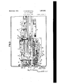
Figure 2 is a vertical sectional view on an enlarged scale of the perforator substantially on the line 22 of Figure 1;
Figure 3 is a plan view of the reperforator;
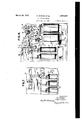
Figure 4; is a rear elevational View of the tape feed control mechanism;
Figure 5 is a front elevation thereof in one position of operation;
Figure 6 is a front elevational view of the tape feed control mechanism in another posrtion of operation; Figure 7 is a detailof the rub out responsive mechanism for preventing operation of the punch solenoid on the reception of a rub out signal; and
Figure 8- is a diagrammatic view of the reperforator and the operating and control circuits therefor.
Referring first to Figures 1, 2 and 3, the supporting structure for the reperforator comprises a base plate 10 and a vertical partition plate 11 carried thereby. The reperforating mechanism is supported on one srde of the plate 11 (on the lefthand side in Flgure 2), and the tape feed control mechanism 1s mounted upon the opposite side thereof.
The reperforating mechanism consists in general of a punch block 12'mountedupon the plate 11 by a lug 13, and having a group of punch pins 14, a punch hammer 15 pivoted at 16, for operating the punch pins, a number of interponent bars 17 adapted to be shifted beneath the punch pins to determine the operation thereof, selecting solenoids 18 for actuating the interponent bars, punch solenoids 19 for operating the punch hammer 15 and a paper feed roller 20 actuated by the punch hammer 15 through a pawl 21. *The tape 22extends from a suitable reel 23 over a tensioning lever 24 pivoted at 25 and provided with a tensioning spring 26 (Figure 5), and thenceacross the top of the punch block 12. I
The particular punch block illustrated is provided with punches of such number and arrangement as to adapt the perforator for use in perforating tape for automatic printing telegraph systems employing a code wherein each character comprises six impulses, although obviously the number of punches and number of units, of the code may tape.
be varied. In the form shown it comprises seven punches 27, of which six are employed to punch the code"holes in the tape, and the seventh or central punch 27 is designed to form feed holesin the tape, this punch being of smaller diameter than the remaining punches.
Each of the punches has an annul'ar enlargement or collar 28 normally resting on the lower wall of the punch block, the
punches extending downwardly thfough the lower wall and upwardlythrough openings in a retracting plate 29 and through openings in the top wall of the punch block. The punches are retained in the lowered position by compression springs 30 surrounding certain of the punch pins. A die plate 31 is secured to the top of the punch block and is provided with openings in alignment with the punch pins. The top of the punch block I is grooved at 32 for the passage of the tape between the die plate and the top of the punch pins. N
Since the feed holes have to be punched for every character and also for .the blanl; por- K 35 adapted to be attracted by the selecting solenoids. The selecting solenoids are mounted uponja shelf 36 carried by the partition plate 11.
The cores 39 and 40 of the punch solenoids 19 are secured to a cross bar 41 having a vertical push rod 42 bearing against the lower side of the hammer 15, to elevate the same against the tension of the retractile spring 43, to raise the interponent members,
which have been shifted, against the punch pins, to force the same upwardly through the The hammer 15 directly engages the paper feed pin 27 to punch the feed hole.
The feed roller 20 is jou'rnaled in a block 44 and in the plate 11, and is provided with a circumferential row of radial pms'45' which engage the control feed openings of the tape to draw the tape through the punch block. Ratchet teeth 46 are formed on the feed roller, against which the pawl 21 is held by a spring-47, the pawl being positioned in one of the ratchet teeth upon the upper movement of the hammer 15, and rotating the, feed wheel one space on the return ,movement of the hammer. reduced and extends through" the plate" '11. A star wheel 48 is attached to this extended end and a jockey roller 49 is held against the One end of the feed wheelisstar wheel by a spring 50 to accurately position the feed wheel after each movement thereof.
The tape is held against the feed wheel and in engagement with the feed pins 45 by an eyelet 52 carried by aframe 53 pivoted on a shaft 54 and urged against the tape by a -lay is unconnected and the marking contact 722; is connected to ground G. The receiving rings of the distributor comprise a solid ring 62, connected to the tongue T of the receiving relay and a segmented ring 63, containing two sets of six segments each, for two channel multiplex'operation. The circuit connections for the first channel only are shown in this figure. Segments l to 6 of channel one are connected to one terminal of the windings'64 of the six selecting relays 65, 66, 67, 68, 69 and 70, the opposite terminals of which are connected, by a common conductor, to a source of potential 71. Each of the relays 65 to 70 have two contacttongues 72 and 73 and cooperating front contacts. Tongues 72 are joined through a common conductor 74 and the back contact and tongue 75 of a break relay 76, to the ground at G1. The front contacts of tongues 72 are connected to one terminal of the windings 64, to provide a locking circuit therefor. Tongues 7 3 of each of the relays 65 to 70 are connected by the common conductor to the source of potential 71, the front contact of each of these relays being connected, respectively, to one terminal of the selecting solenoids 1 to'6' of the reperforator. The opposite terminals of the selecting solenoids are connected b a common conductor 77 to the ground at '2. The local ring 58 comprises asolid ring ,78 grounded at G3 and a segmentedring 79 having twelve segments. Segment 9 is connected to one terminal of the winding of the relay 80, the opposite terminal ofwhich is connected to the source of potential 71 and segment 11 is connected to one terminal of the winding of the break relay 76, the opposite terminal being connected to the source of potential at 71. Relay 80 has a single contact tongue 81 connected to the source ofpotential 71 and a corresponding front contact, connected by conductor 82, to one end of the winding of a locking relay 83, the opposite end of which is grounded at G2. The front contact of relay '88 is connected through a resistance R to the relay winding and also directly through the winding of the punch solenoids 19'to the ground G2. Tongue 84 oflrelay 83 is connected through normally closed contacts 85, contacts 86 and contacts 87, to a source of potential 88. I 1
The contacts 86 are adapted to be openedon the upward movement of the plunger of the printing solenoid by an extension 89 carried by the cross bar 41 (Figure 2).
Assuming that signals are received over channel one for a particular code combina: tion, as for instance the letter W, in which the signals 1, 2 and 5 are marking, the receiving relay 56 will operate to apply the. ground G to the windings of the relays 65, 66 and 69, as the distributor brush B passes over receiving segments 1, 2 and 5, thus causing these relays to pick up and complete their I locking circuits through the tongues 72. At the same time the battery 71 is applied through the tongues 73 of relays 65, 66 and 69, to the selecting solenoids 1', 2', and 5' to shift the interponent bars of these magnets beneath the corresponding punch ins. Upon the continued rotation o the brush B on to segment 9, the ground G3 is applied to the relay 80, which picks up and applies the battery 71, through .conductor 82, to the locking relay83 which is thus operated to complete the circuit for the punch solenoids 19, this circuit extending from the battery 88 through the contacts 87 86and andfront contact of the relay 83, thence through the punch solenoids and to ground G2. At the same time a locking circuit is established for the relay 83 fromthe tongue 84, through the resistance R to the relay winding and thence to the ground G2. The solenoids 19, effect the perforation of the tape in accordance with the setting ofit-he interponent bars 17, at the same time operatingthe tape feed mechanism through the pawl 21, to advance the tape into the succeeding perforating position. Upon the upward stroke of the printing solenoid the contact 86 is opened to break the looking circuit for the relay 83.
Upon passage of the brush B across segment 11, the break relay 7 6 is operated to remove the ground G1 from the selecting relays 65 to 70, allowing them to return to normal and thus interrupting the circuits to the selecting solenoids 18, whereby the interponent bars are returned to normal position in readiness for the succeeding code signal.
When no code signals are being received over channel one the relays 65 to' 70 remain unoperated. However, during each revolution of the brush B, the relay 80 operates to actuate the punch solenoids 19 and the tape feed mechanism, to advance the tape continuously through the perforator. Since the interponentbars 17 are not shifted during this operation, only the tape feed hole is punched.
The mechanism for limiting this continuous feeding of the tape through the reperforator during idle periods of the channel, to a predetermined length of tape will now be described.
A stub shaft 92 secured to the pin plate 11, has a bushing 93 upon which a lever 94 is journaled. The lever carries a pinion 95 normally held in mesh with a small gear 96 mounted rigidly upon the extended end of the feed roller 20. A gear wheel 97 in mesh with the pinion 95, is journaled upon a bushing 98 fixed to the shaft 92. Bushing 98 terminates in a disc 99 spaced from the gear 97 and a spiral spring 100 is mounted between the disc and the gear wheel 97. The inner end of a 1 spring is anchored by a pin 101, carried by the disc and the outer end of the spring is secured to a pin .102 carried by the gear wheel. The gear wheel also carries a pin 103 near its outer edge which, when the gear is rotated sufii- 2o ciently, engages the inclined face 104 of a contact block 105, pivoted at 106, to depress the same against the tension of the spring 107,
to open the contacts-85. Current is conducted to the lower contact from a terminal 108 through the spring 109 and contact strip 110. The upper contact 85 is mounted upon a bracket 112 secured to the plate 11 and is adjustable in the horizontal arm of the bracket. The gear wheel 97 is normally held by the 80 spring 100, with the pin 103 out of contact with the inclined surface 104, as shown in Figure 5 and rotates in a counterclockwise direction to bring the pin into contact with the switch block, as shown in Figure 6.
The lever 94 has a link 113 pivoted thereto and to the vertical arm of a-bell crank lever 114, pivoted at 115. The horizontal arm of the bell crank lever is connected by a link 116 to the horizontal arm of a second bell crank lever 117, by means of a pin 118, extending through an opening 119 in the plate 11. The vertical arm of the lever 117 comprises a bail having a horizontal portion 120extending v ment with the gear 96, the lever 94 being across the interponent bars 17 slightly thereabove and slightly in advance of projections 122 integral with the interponent bars, so, that when any one of the interponent bars is shifted, in response to a selecting cond tion, the bail is engaged by theprojection 122 to rock the lever 117 and thence to withdraw the pinion 95 from engagement with the gear 96, as shown in Figure 4. The horizontal arm of the bell crank lever 114, when elevated at this time, is locked in its upperposition by engagement of the end thereof with a shoulder .123, of a latch 124, pivoted at 125 and urged towards the bell crank lever by a spring 126. i The latch 124 is arranged to be moved from a push rod 127, pivoted tothe latch and to the plate 11 through the pin and slot 128. The
push rod terminates at one side of the gear.
. wheel 97 in an inturned end 129 and is enengagement with the bell crank lever 114, by
gaged by a dog 130, carried by the gear wheel,
when the gear is in its normal or initial posiv tion.
The operation of the tape feed control mechanism is as follows: Assume the distributor 57 to be rotating idly, that is without signals being transmitted over channel one, so that upon each revolution thereof the solenoid 19 operates to form a feed hole in the tape and to advance the tape through the perforator. Since none of the selecting magnets are energized, all of the interponent bars 17 are held in their normal position with the projections 122 out of contact with the bell crank lever,117, thus permitting the pinion '95 to be held in mesh with the gear 96, on the feed roller shaft.- Therefore, the gear wheel 97 is rotated from the position shown in Figure 5, to that shown in Figure 6, in a counterclockwise direction, to bring the pin 103 in engagement with the contact block 105, to open the contacts 85. By reference to Figure 8 it will be noted that the opening of this contact interrupts the operating circuit of the perforator solenoid from the source of current 88 so that it is no longer operative to form the feed holes in the tape and to advance the tape through the perforator. Obviously,
the pin 103 may be provided at any point along the gear wheel so as to permit the tape to be fed forwardat anydesired number of spaces prior to the opening of the contacts 85 and should be positioned so as to permit a sufficient length of tape to be advanced after cessation of the code signals to bring the' last code signal perforation in operative position in the tape transmitter, which may be located adjacent to the perforator.
The gear wheel 97 is maintained in the position shown in Figure 6 to hold the contacts 85 open until the next selecting signal is received, at which time one of the interponent bars will be shifted forward to rock the lever 94 and withdraw the pinion 95 from engagelocked in this position by the latch 124. The gear wheel 97 being thus released rides backwards in aclockwise. direction under the action of the spring 10.0 until the dog 130 strikes the inturned end of the lever 127 to trip the latch 124 and again permit the pinion 95 to move into engagement w'th the gear 96. v If no further code signals ai e received the previous cycle is repeated. However, if a succession of code signals are received the pinion 95 is moved out of engagement with the gear 96 for each new selecting condition, to permit the gear wheel to be reset in its initial position.
It will be understood, of course, that the tape may be advanced through the perforator any number of spaces up to the predetermined 'maximum as determined by the counting or control mechanism and the control: mechanism will be set back to its initial position upon the receipt of the next code signal, from Whatever position it may be in.
The locking relay 83 shown in Figure 8 is mounted upon the base plate 10 as shown in Figure 5.
It is obvious that various modifications and changes may be made in the construction of I the tape feed control or counting mechanism and that the same may be applied to devices other than reperforators and hence we do not desire to be limited to the exact details shown and described, except in accordance with the appended claims.
What we claim is:
1. In a tape perforator, a perforatlng mechanism, a selecting mechanism responsive to signals for the Baudot code for controlling said perforating mechanism, means for advancing the tape through the perforator one space for each selecting code combination applied to said selective mechanism, and means for automatically advancing the tape through the perforator a predetermined maximum number of spaces upon inaction of said selectng mechanism.
2. In a tape perforator, a perforating mechanism, a selecting mechanism responsive to character code groups consisting of mixed marking and spacing conditions for controlling said perforating mechanism, a tape feed mechanism for advancing the tape through the perforator one space for each selecting group applied to the selecting mechanism,
said tape feed mechanism automatically advancing the tape through the perforator upon inaction of said selecting mechanism and counting mechanism set into operation when a signal group consisting of spacing conditions only is applied tosaid selectmg mechanism, to discontinue the operation of the tape feed mechanism after the tape has advanced through the perforator a predetermined number of spaces. v
3. In a tape perforator, a perforating mechanism, a selecting mechanism controlling said perforating mechanism, and a tapeone space for each selecting group, said tape feed mechanism also advancing blank tape through the perforator for each non-selecting slgnal group, a counting mechanism for de. termining the length of blank tape advanced through the perforator, and means responsive to a marking condition in anysignal group for resetting said counting mechanism upon each operation of the selecting mechanism.
5. In combination, a synchronously operating distributor, a tape perforator, a perforating mechanism, a selecting mechanism controlled by said distributor for said perforating mechanism, a'tape feed mechanisnr controlled by said distributor for adv'anclng the tape through the perforator one space for each selecting condition, said tape feed-mechanism also advancing blank tape through the perforator upon inaction of said selecting mechanism, a counting mechanism for determining the length of blank tape advanced through the perforator, means for starting said counting mechanism into operation after each operation of the perforating mechanism, and means for restoring the same to its initial position-upon eachopera tion of the selecting mechanism.
6. In a tape reperforator, a perforating mechanism, a selecting mechanism responsive to received signals, a tape feed mechanism for continuously advancingtape through the perforating mechanism, counting means normally in engagement with said tape feed mechanism for discontinuing the operation thereof after a predeterm'ned length of tape has been advanced thro gh the perforating mechanism, and means operating upon the in one limit of movement thereof to discon tinue the operation of the tape feed mechanism, and means acting upon the reception of a marking condition in each selecting group for setting said first means in its otherlimit of movement.
8. In atape reperforator, a perforating mechanism, a selecting mechanism responsive to received signals, a tape feed mechanism for continuously advancing tape through the perforating mechanism, means actingwhen no selecting conditions are set up for rendering said perforating and tape feed mechanism inoperative after a predetermined length of tapehas been advanced, and means responsive to a rub-out signal for rendering said perforating and tape feed mechanism immediately inoperative.
9. In a tape reperforator, a perforating mechanism, a selecting mechanism responsive to received signals, a tape feed mechanism for continuously advancing tape through the perforating mechanism, means acting when no selecting conditions are set up for rendering said perforating and tape feed mechanism inoperative after a predetermined length of tape has been advanced, means for again rendering said perforating and tape feed mech anism operative upon setting up of a selecting condition and separate means for rendering the perforating and tape feed mechanism in operative while a rub-out selecting condition is set up.
10. In a tape reperforator, a perforating mechanism, a selecting mechanism responsive to received signals, a tape feed mechanism, a
continuously rotating element operating in synchronism wlth the received signals. said element controlling said perforating and tape feed mechanism to continuously perforate feed holes and feed the tape through the per forating mechanism, a gear wheel, an intermediate pinion in mesh with said gear wheel, a gear driven by said tape feed mechanism, means for causing engagement of said pinion with said gear when the selecting mechanism is unoperated'and for causing disengagement thereof when said selecting mechanism is operated to set up a selecting condition, said gear wheel on predetermined rotation thereof rendering said perforating and tape feed mechanism inoperative, and means for returning said gear Wheel to its initial position upon disengagement of said pinion from said gear.
- 11. In a tape reperforator, a perforating mechanism, a selecting mechanism responsive to received signals, a tape feed mechanism, means for continuously operating said perforator and tape feed mechanism to feed the tape through the perforator continuously, a gear Wheel, an intermediate pinion in mesh with said gear wheel, a gear driven by said tape feed mechanism, means for causing engagement of said pinion with said gear when the selecting mechanism is unoperated and for causing disengagement thereof when said selecting mechanism is operated to set up a selecting condition, said gear Wheel on predetermined rotation thereof rendering said perforating and tape feed mechanism inoperative, and means for returning said gear wheel to its initial position upon disengagement of said pinion from said gear.
12. In a tape reperforator, a perforating mechanism, a selecting mechanism responsive to received signals, a tape feed mechanism, means for continuously operating said perforator and tape feed mechanism to feed the tape through the perforator continuously, a gear wheel, an intermediate pinion in mesh with said gear wheel, a gear driven by said tape feed mechanism, means for caus- When the selecting mechanism is unoperated, means acting upon operation of said selecting mechanism for disengaging said pinion and gear, means for returning said gear wheel to its initial position during disengagement of said pinion and gear, and means independent of the selecting mechanism of holding said pinion and gear disengaged during the return movementof said gear wheel.
13. In a tape perforator, a perforating mechanism responsive to signals 'of the Baudot code, comprising an individual element for each unit of the code movable into marking or spacing position in accordance with the code combination, a tape feeding mechanism, a punch for perforating feed holes in the tape, means for continuously operating said punch and tape .feed mechanism when said elements are all in spacing position, means rendering said punch and tape feed mechanism inoperative after a predetermined amount of blank tape has been perforated, and means controlled by any of said movable elements when in marking position for again rendering the punch and tape feed mechanism operative.
14. In a tape recorder, a recording mechanism, a selective mechanism responsive to signals of the permutation code type for controlling said recording mechanism, means for advancing the tape through the recorder one space foreach selecting code combination applied to said selecting mechanism and for automatically advancing the tape through 15. In a tape recorder, a recording-mechanism, a selecting mechanism responsive to received signals, a tape feed mechanism for continuously advancing the tape through the recorder mechanism, means acting when no selecting conditions are received for rendering said tape feed mechanism inoperative after a predetermined length of tape has been advanced and means responsive to a rub out ing engagement of said pinion with said gear signal for rendering said tape feed mechanism immediately inoperative.
16. In a telegraph receiving instrument, a selecting mechanism responsive to receiving signals of the permutation code type, a tape supply, means controlled by said selecting mechanism for producing a record on said tape, a normal tape feed mechanism and auxiliary means acting automatically upon cessa- 10 tion of said permutation code signals for ejecting an additional limited amount of tape from the receiving instrument.
In testimony whereof we aiiix our signatures. v r RAY HOOVER.
FRANK J. HAUPT.
Priority Applications (1)
| Application Number | Priority Date | Filing Date | Title |
|---|---|---|---|
| US468921A US1851838A (en) | 1930-07-18 | 1930-07-18 | Tape reperforator |
Applications Claiming Priority (1)
| Application Number | Priority Date | Filing Date | Title |
|---|---|---|---|
| US468921A US1851838A (en) | 1930-07-18 | 1930-07-18 | Tape reperforator |
Publications (1)
| Publication Number | Publication Date |
|---|---|
| US1851838A true US1851838A (en) | 1932-03-29 |
Family
ID=23861760
Family Applications (1)
| Application Number | Title | Priority Date | Filing Date |
|---|---|---|---|
| US468921A Expired - Lifetime US1851838A (en) | 1930-07-18 | 1930-07-18 | Tape reperforator |
Country Status (1)
| Country | Link |
|---|---|
| US (1) | US1851838A (en) |
Cited By (3)
| Publication number | Priority date | Publication date | Assignee | Title |
|---|---|---|---|---|
| US2566931A (en) * | 1948-11-23 | 1951-09-04 | Ibm | Record card punching machine |
| US2604537A (en) * | 1950-02-10 | 1952-07-22 | Ralph L Thompson | Electrically operated printer receiver |
| US2652116A (en) * | 1948-03-09 | 1953-09-15 | Bell Telephone Labor Inc | Perforating system |
-
1930
- 1930-07-18 US US468921A patent/US1851838A/en not_active Expired - Lifetime
Cited By (3)
| Publication number | Priority date | Publication date | Assignee | Title |
|---|---|---|---|---|
| US2652116A (en) * | 1948-03-09 | 1953-09-15 | Bell Telephone Labor Inc | Perforating system |
| US2566931A (en) * | 1948-11-23 | 1951-09-04 | Ibm | Record card punching machine |
| US2604537A (en) * | 1950-02-10 | 1952-07-22 | Ralph L Thompson | Electrically operated printer receiver |
Similar Documents
| Publication | Publication Date | Title |
|---|---|---|
| US2334534A (en) | Teletypewriter | |
| US1851838A (en) | Tape reperforator | |
| US2143828A (en) | Telegraph printer-reperforator | |
| US1941916A (en) | Combined keyboard transmitter and perforated tape transmitter | |
| US2340801A (en) | Record controlled perforating apparatus | |
| US1863479A (en) | Rub out signal deleter for tape transmitters | |
| US2370989A (en) | Code translating recorder | |
| US2264052A (en) | Automatic quotation system | |
| US1579999A (en) | Cable telegraphy | |
| US2566972A (en) | System for analyzing code perforations | |
| US2193213A (en) | Printing apparatus | |
| US2254814A (en) | Telegraph signal storage apparatus | |
| US1394439A (en) | Code-transposing apparatus for telegraph systems | |
| US2331914A (en) | Telegraph transmitting system | |
| US2666095A (en) | Telegraph printer | |
| US2237130A (en) | Transmission system for statistical data | |
| US2192352A (en) | Receiving perforator | |
| US3014093A (en) | Printing telegraph storage transmistter with card reader and handling mechanism | |
| US2194663A (en) | Telegraphic transmitting device | |
| US1811132A (en) | Selective system and apparatus therefor | |
| US1835466A (en) | Printing mechanism for card controlled accounting machines | |
| US1931790A (en) | Receiving recorder | |
| US2262014A (en) | Teletypewriter transmitting and receiving system | |
| US2106693A (en) | Home record cut-out assembly | |
| US2213560A (en) | Transmission system for statistical data |