US1851772A - Furnace - Google Patents
Furnace Download PDFInfo
- Publication number
- US1851772A US1851772A US401549A US40154929A US1851772A US 1851772 A US1851772 A US 1851772A US 401549 A US401549 A US 401549A US 40154929 A US40154929 A US 40154929A US 1851772 A US1851772 A US 1851772A
- Authority
- US
- United States
- Prior art keywords
- arch
- furnace
- box
- indicated
- ceiling
- Prior art date
- Legal status (The legal status is an assumption and is not a legal conclusion. Google has not performed a legal analysis and makes no representation as to the accuracy of the status listed.)
- Expired - Lifetime
Links
- 239000007789 gas Substances 0.000 description 6
- 239000002245 particle Substances 0.000 description 5
- 239000002893 slag Substances 0.000 description 5
- 238000010276 construction Methods 0.000 description 3
- 239000000446 fuel Substances 0.000 description 3
- 238000010438 heat treatment Methods 0.000 description 3
- 238000002485 combustion reaction Methods 0.000 description 2
- 239000007788 liquid Substances 0.000 description 2
- 239000007787 solid Substances 0.000 description 2
- 230000001133 acceleration Effects 0.000 description 1
- 230000015572 biosynthetic process Effects 0.000 description 1
- 239000012809 cooling fluid Substances 0.000 description 1
- 239000000463 material Substances 0.000 description 1
- 238000000926 separation method Methods 0.000 description 1
- XLYOFNOQVPJJNP-UHFFFAOYSA-N water Substances O XLYOFNOQVPJJNP-UHFFFAOYSA-N 0.000 description 1
Images
Classifications
-
- F—MECHANICAL ENGINEERING; LIGHTING; HEATING; WEAPONS; BLASTING
- F23—COMBUSTION APPARATUS; COMBUSTION PROCESSES
- F23C—METHODS OR APPARATUS FOR COMBUSTION USING FLUID FUEL OR SOLID FUEL SUSPENDED IN A CARRIER GAS OR AIR
- F23C99/00—Subject-matter not provided for in other groups of this subclass
-
- F—MECHANICAL ENGINEERING; LIGHTING; HEATING; WEAPONS; BLASTING
- F23—COMBUSTION APPARATUS; COMBUSTION PROCESSES
- F23C—METHODS OR APPARATUS FOR COMBUSTION USING FLUID FUEL OR SOLID FUEL SUSPENDED IN A CARRIER GAS OR AIR
- F23C2700/00—Special arrangements for combustion apparatus using fluent fuel
- F23C2700/06—Combustion apparatus using pulverized fuel
- F23C2700/063—Arrangements for igniting, flame-guiding, air supply in
Definitions
- the invention relates to furnaces, and especially to furnaces for burning pulverulent fuel, although it is not limited thereto necessarily, and has for its object to provide an improved construction and arrangement in a furnace of this type.
- the ligure is a vertical sectional view of a furnace structure embodying the invention.
- 1 indicates the outer shell of a boiler, a portion of the boiler only being illustrated, 2 indicates ⁇ the fire box, and 3 indicates the rear wall or back tube plate.
- the usual tubes in the back tube plate are indicated at 4.
- the tube plate 3 is provided with a downward extension which forms a water leg 5.
- 6 indicates the crown sheet or ceiling of the boiler, and 7 indicates a fire door ⁇ ring in the front wall or outer shell of the fire box.
- a combustion chamber 10 Below the ire box 2 is a combustion chamber 10, the walls 11 of which are supported by the ash tray 12 and extend vertically upward partly into the ire box 2 as is indicated at 13.
- a primary burner 14 Extending along each side of the combustion chamber is a primary burner 14 to which cooling fluid Ais supplied by conduits 15 andto which fuel and air are supplied by a ⁇ conduit 16.
- This burner may be of any suitable construction. It is indicated diagrammatically as being of the construction disclosed in our parent application above referred to. 17 indicates a passage through which air is supplied to the fire box, the opening to the passage being controlled by a hinged door 18.
- the present invention relates particularly to an arrangement for preventing the formation of slag.
- I provide in the fire box an arch 19 which may be supported in any suitablev manner.
- This arch is-,designed with ⁇ particular consideration ofthe tendency to form slag nests at the rearface of the tube plate 3. To this end the arch is made longer than the normal arch, and its inclination is less steep.
- the arrangement is such that the area (indicated by the arrows between the front wall and the rear edge 20 of the arch is smaller than the area between its rear edge and the crown sheet 6 (indicated by the arrows y-y).
- the velocity of the gases obtained their maximum after they had passed through this area and assumed the horizontal direction of flow indicated by the arrow Z1, but, with the relative areas as designated in the present instance, the velocity of the gases will be at maximum when flowing through the area www (indicated by the arrow Z1), and will decrease when the gases are deflected horizontally.
- the free area forms a nozzle-like constriction in the path of the flames which latter occupy the entire area of the lower part of the fire box. This constriction causes an acceleration of liquid and solid particles contained in said flames whereby said particles are hurled against the ceiling of the iire box.
- the separation 0f said particles from the gaseous material before the flames reach the tube wall 3 is further improved by the inclined arrangement of the arch such that the cross sectional area y-y is larger than that of -w, which consequently causes a retarded motion of the fiames towards the heating tubes.
- This arrangement comparatively heavy particles of slag ydo not follow the changed direction of the gases but move on in the direction of the arrow Z1 and are hurled against the crown sheet 6, where they are granulated so that the gases arriving at tube plate 3 are free from slag in plastic condition, and therefore nests will not form on the tube wall. It will thus be seen that by the improved arrangement I am enabled to free the gases from slag in a plastic condition.
- a fire box comprising front, rear and side walls and a ceiling, pulverulent fuel feeding a means provided along said side walls whereby the produced lames occupy the entire lower space of said fire box, heating tubes communicating with the re boX, said rear wall being provided with openings for said heating tubes, and means causing an accelerated motion of liquid and solid particles contained in the flames in the direction to the front part of said ceiling and a retarded motion in the direction to said rear wall and tubes, said means comprising an arch inclined towards the ceiling and extending from said rear wall towards said front wall and leaving a free space between its free edge and said front wall which is narrower than the space formed between its free edge and said ceiling.
Landscapes
- Engineering & Computer Science (AREA)
- Chemical & Material Sciences (AREA)
- Combustion & Propulsion (AREA)
- Mechanical Engineering (AREA)
- General Engineering & Computer Science (AREA)
- Filling Or Discharging Of Gas Storage Vessels (AREA)
Description
March 29, 1932. W KLEINOW FURNACE Filed Oct. 22, 1929 Inventor: \)(/a|texr` Klenow,
H'LS Attorng.
Patented Mar. 29, 1932 WALTER KLEINOW, or HENNrGsDonF, NEAR, BERLiN,
FURNACE Application filed October 22, 1929, Serial No.l 401,549, and in Germany May 1, 1925,.
The subject matter of this application was originally disclosed and claimed in the joint application of myself and Albert Morgenroth, Friedrich Reinhardt and Wilhelm Bauer, Serial No. 17 8,073, filed March 24, 1927, now Patent No. 1,739,035, dated December 10, 1929.
The invention relates to furnaces, and especially to furnaces for burning pulverulent fuel, although it is not limited thereto necessarily, and has for its object to provide an improved construction and arrangement in a furnace of this type.
For a consideration of what I believe to be novel and my invention, attention is directed to the following specification and the claim appended thereto.
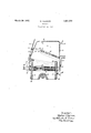
In the drawing, the ligure is a vertical sectional view of a furnace structure embodying the invention.
Referring to the drawing, 1 indicates the outer shell of a boiler, a portion of the boiler only being illustrated, 2 indicates `the fire box, and 3 indicates the rear wall or back tube plate. The usual tubes in the back tube plate are indicated at 4. The tube plate 3 is provided with a downward extension which forms a water leg 5. 6 indicates the crown sheet or ceiling of the boiler, and 7 indicates a fire door` ring in the front wall or outer shell of the fire box. Below the ire box 2 is a combustion chamber 10, the walls 11 of which are supported by the ash tray 12 and extend vertically upward partly into the ire box 2 as is indicated at 13.
Extending along each side of the combustion chamber is a primary burner 14 to which cooling fluid Ais supplied by conduits 15 andto which fuel and air are supplied by a `conduit 16. This burner may be of any suitable construction. It is indicated diagrammatically as being of the construction disclosed in our parent application above referred to. 17 indicates a passage through which air is supplied to the fire box, the opening to the passage being controlled by a hinged door 18.
The present invention relates particularly to an arrangement for preventing the formation of slag. According to the invention I provide in the fire box an arch 19 which may be supported in any suitablev manner. This arch is-,designed with `particular consideration ofthe tendency to form slag nests at the rearface of the tube plate 3. To this end the arch is made longer than the normal arch, and its inclination is less steep. The arrangement is such that the area (indicated by the arrows between the front wall and the rear edge 20 of the arch is smaller than the area between its rear edge and the crown sheet 6 (indicated by the arrows y-y). Heretofore the velocity of the gases obtained their maximum after they had passed through this area and assumed the horizontal direction of flow indicated by the arrow Z1, but, with the relative areas as designated in the present instance, the velocity of the gases will be at maximum when flowing through the area www (indicated by the arrow Z1), and will decrease when the gases are deflected horizontally. In other words, the free area forms a nozzle-like constriction in the path of the flames which latter occupy the entire area of the lower part of the fire box. This constriction causes an acceleration of liquid and solid particles contained in said flames whereby said particles are hurled against the ceiling of the iire box. The separation 0f said particles from the gaseous material before the flames reach the tube wall 3 is further improved by the inclined arrangement of the arch such that the cross sectional area y-y is larger than that of -w, which consequently causes a retarded motion of the fiames towards the heating tubes. With this arrangement comparatively heavy particles of slag ydo not follow the changed direction of the gases but move on in the direction of the arrow Z1 and are hurled against the crown sheet 6, where they are granulated so that the gases arriving at tube plate 3 are free from slag in plastic condition, and therefore nests will not form on the tube wall. It will thus be seen that by the improved arrangement I am enabled to free the gases from slag in a plastic condition.
What I claim as new and desire to secure by Letters Patent of the United States is A fire box comprising front, rear and side walls and a ceiling, pulverulent fuel feeding a means provided along said side walls whereby the produced lames occupy the entire lower space of said lire box, heating tubes communicating with the re boX, said rear wall being provided with openings for said heating tubes, and means causing an accelerated motion of liquid and solid particles contained in the flames in the direction to the front part of said ceiling and a retarded motion in the direction to said rear wall and tubes, said means comprising an arch inclined towards the ceiling and extending from said rear wall towards said front wall and leaving a free space between its free edge and said front wall which is narrower than the space formed between its free edge and said ceiling.
In Witness whereof, I have hereunto set my hand this 5th day of October, 1929.
WALTER KLEINOW.
Applications Claiming Priority (1)
| Application Number | Priority Date | Filing Date | Title |
|---|---|---|---|
| DE1851772X | 1925-05-01 |
Publications (1)
| Publication Number | Publication Date |
|---|---|
| US1851772A true US1851772A (en) | 1932-03-29 |
Family
ID=7746043
Family Applications (1)
| Application Number | Title | Priority Date | Filing Date |
|---|---|---|---|
| US401549A Expired - Lifetime US1851772A (en) | 1925-05-01 | 1929-10-22 | Furnace |
Country Status (1)
| Country | Link |
|---|---|
| US (1) | US1851772A (en) |
Cited By (1)
| Publication number | Priority date | Publication date | Assignee | Title |
|---|---|---|---|---|
| US6328246B1 (en) | 1999-07-01 | 2001-12-11 | Sca Hygiene Products Ab | Hold for rolls of a web-shaped material |
-
1929
- 1929-10-22 US US401549A patent/US1851772A/en not_active Expired - Lifetime
Cited By (1)
| Publication number | Priority date | Publication date | Assignee | Title |
|---|---|---|---|---|
| US6328246B1 (en) | 1999-07-01 | 2001-12-11 | Sca Hygiene Products Ab | Hold for rolls of a web-shaped material |
Similar Documents
| Publication | Publication Date | Title |
|---|---|---|
| US1734669A (en) | Pulverized-fuel-burning furnace | |
| US1851772A (en) | Furnace | |
| US1846647A (en) | Pulverized fuel furnace | |
| US579740A (en) | Fireplace gas-heater | |
| US1985517A (en) | Oil lantern | |
| US1762319A (en) | Art of generating steam by the burning of fuel in suspension | |
| US1737173A (en) | Furnace | |
| US1034799A (en) | Device for fuel-saving stoves. | |
| USRE16984E (en) | Btjbneb asx mexhqjb of burning jpoel | |
| US6720A (en) | Wtlijam souks | |
| US1930566A (en) | Flame baffle for pulverized fuel furnaces | |
| US1679724A (en) | Furnace | |
| US1918401A (en) | Pulverized fuel locomotive boiler | |
| US1330972A (en) | Air-deflector for fire-box doors | |
| US2071678A (en) | Gas generating boiler for central heating | |
| US6719A (en) | Cooking-stove | |
| US1938462A (en) | Movable stove | |
| US1421898A (en) | Pulverized-fuel furnace | |
| US1731448A (en) | Boiler construction | |
| US1541355A (en) | Boiler | |
| US1781310A (en) | Finely-divided-fuel-burning furnace construction | |
| US349736A (en) | Hot-air furnace | |
| US960904A (en) | Stove. | |
| US750860A (en) | Smoke-consumer | |
| US1510994A (en) | Pulverized-fuel-burning furnace |