US1851747A - Hinged support - Google Patents
Hinged support Download PDFInfo
- Publication number
- US1851747A US1851747A US396649A US39664929A US1851747A US 1851747 A US1851747 A US 1851747A US 396649 A US396649 A US 396649A US 39664929 A US39664929 A US 39664929A US 1851747 A US1851747 A US 1851747A
- Authority
- US
- United States
- Prior art keywords
- links
- fall
- board
- floor
- hinged
- Prior art date
- Legal status (The legal status is an assumption and is not a legal conclusion. Google has not performed a legal analysis and makes no representation as to the accuracy of the status listed.)
- Expired - Lifetime
Links
Images
Classifications
-
- E—FIXED CONSTRUCTIONS
- E05—LOCKS; KEYS; WINDOW OR DOOR FITTINGS; SAFES
- E05C—BOLTS OR FASTENING DEVICES FOR WINGS, SPECIALLY FOR DOORS OR WINDOWS
- E05C17/00—Devices for holding wings open; Devices for limiting opening of wings or for holding wings open by a movable member extending between frame and wing; Braking devices, stops or buffers, combined therewith
- E05C17/02—Devices for holding wings open; Devices for limiting opening of wings or for holding wings open by a movable member extending between frame and wing; Braking devices, stops or buffers, combined therewith by mechanical means
- E05C17/04—Devices for holding wings open; Devices for limiting opening of wings or for holding wings open by a movable member extending between frame and wing; Braking devices, stops or buffers, combined therewith by mechanical means with a movable bar or equivalent member extending between frame and wing
- E05C17/32—Devices for holding wings open; Devices for limiting opening of wings or for holding wings open by a movable member extending between frame and wing; Braking devices, stops or buffers, combined therewith by mechanical means with a movable bar or equivalent member extending between frame and wing consisting of two or more pivoted rods
Definitions
- the invention relates generally to hinged supports for furniture and more particularly to a hinged support for the fall-board or closure member of a desk, cabinet, or the like, which is hingedabout an axis lying along the upper front edge of the floor of the cabinet.
- the general object of this invention is t0 provide a new and improved hinged support for the fall-board of a desk in which the fallboard pivots about an axis lying along the upper front edge of the floor of the desk, said hinged support being adapted to be mounted on the floor and fall-board and occupying only a minimum amount of space of the upper surface of the iioorV and fall-board which would otherwise be available for use in the functions of a desk.
- Another object kof the invention is to provide such a hinged support whose parts may be stamped from sheet metal and are comparatively small and simple in form so that .the support is inexpensive to manufacture.
- a further object is to provide a hingedV support which includes two connected links having gear teeth on their adjacent ends for equalizing the movement of said links ywhen opened or closed.
- a hinged supportfor the fall-boardl of al desk comprising two members ada ted to be mounted on the floor of the desk an the fall-board respectively and having their adjacent ends hinged together, two channelshaped links, each having its outer end pivoted to one of said members and having gear teeth cut on its inner end, and a block mounted within the channels and pivoted t0 Eig. 2 .is a vertical section through the cabinet with the fallb0ardopen showing the side elevation of the hinged support.
- Fig. 3 is a section similar to that shown in Fig. 2 except that the fall-board is closed.
- F ig. 4 is aperspective view of one of the links.
- l Fig. 5 is a perspectiveview vof the block connecting the two links.
- va desk is shown for which e The desk ⁇ the hinged supportis suitable. comprises a side wallylO, a floor 11, and a closure member or fall-board 12 hinged about an axis. lying along the upper front edge of the floor 11., While it is contemplated that two such hinged supports will be vused for each fall-board, only one has been shownin the drawings as the other is exactly similar.
- the hinged support illustrated herein comprises generally two members liinged together and adapted to be mounted on the floor 11 and fall-board 12 respectively, and a link structure forming a strut comprising two links pivotally attached to the floor and the fallboar'd by means of said members, means connectingthe adjacent ends of said links, and means for equalizing their movement when the fall-board 12 is opened'or closed.
- a member 13, comprising a fiat strip of metal, is adapted to be mounted in a mortise cut in the upper surface of the floor 11 and attached thereto as by screws.
- a second member .14 is adapted to be ⁇ g similarly mounted in a mortise cut in the fallboard 12 and alined withl the member 13.
- the adjacent ends of said members are curled around a pin 15 to forma hinge.
- a lug 16 is formed by bending a portion of the metal upwardly.
- the invention includes a link structure forming a strut comprising two links 17 pivotally attached to the floor 11 and the fall-board 12 by means of the members 13 and 14.
- the links 17 are formed in a channel shape, opening downwardly, and are pivotally attached at their outer ends to the lugs 16 with the flanges of the channel straddling the lug.
- Such construction gives greater strength and permits a klighter metal to be used.
- Means are provided for connecting the adjacent ends of the links 17 comprising a third link or a block 2O mounted within the channels and pivotally connected at 21 to each of said links.
- the block 2O is notched in its lower edge to form two legs straddling the hinged portion of the members 13 and 14 and adapted to abut against the upper surfaces of the members when the fall-board is in ahori'zontal position.
- thelinks 17 and the block 2O lie above the upper surfaces of the floor 11 and fall-board ⁇ 12 and the block 20v abuts against the members 13'and 14 to limit the opening oi the fall-board to a horizontal position.
- a hinge comprising two hinge leaves each having a lug, two channel shaped links each having its outer end pivoted to one of said lugs, with the lugs embraced between the flanges of the links, and a block pivotal-V ly connecting the adjacent ends of the links, said block being embraced between the flanges of the links.
Landscapes
- Engineering & Computer Science (AREA)
- Mechanical Engineering (AREA)
- Hinges (AREA)
- Tables And Desks Characterized By Structural Shape (AREA)
Description
Patented Mar.; 29,V 1932 UNITED STATES'- REUBEN A. ALDEEN AND THORSTEN'H. ERICKSON, onnocxronn, ILLINOIS,` AssmNons TO AMERICAN CABINET HARDWARE COREORA'IION,` OF ROCKFORD, ILLINOIS, A-
CORPORATION OF ILLINOIS HINGE!) SUPPORT Application nied oc'wiar` 2,1929.y serial No. :masiak The invention relates generally to hinged supports for furniture and more particularly to a hinged support for the fall-board or closure member of a desk, cabinet, or the like, which is hingedabout an axis lying along the upper front edge of the floor of the cabinet.
The general object of this invention is t0 provide a new and improved hinged support for the fall-board of a desk in which the fallboard pivots about an axis lying along the upper front edge of the floor of the desk, said hinged support being adapted to be mounted on the floor and fall-board and occupying only a minimum amount of space of the upper surface of the iioorV and fall-board which would otherwise be available for use in the functions of a desk.
Another object kof the invention is to provide such a hinged support whose parts may be stamped from sheet metal and are comparatively small and simple in form so that .the support is inexpensive to manufacture.
A further object is to provide a hingedV support which includes two connected links having gear teeth on their adjacent ends for equalizing the movement of said links ywhen opened or closed.
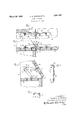
In pursuance of the above objects we aim to provide a hinged supportfor the fall-boardl of al desk comprising two members ada ted to be mounted on the floor of the desk an the fall-board respectively and having their adjacent ends hinged together, two channelshaped links, each having its outer end pivoted to one of said members and having gear teeth cut on its inner end, and a block mounted within the channels and pivoted t0 Eig. 2 .is a vertical section through the cabinet with the fallb0ardopen showing the side elevation of the hinged support.
Fig. 3 is a section similar to that shown in Fig. 2 except that the fall-board is closed. F ig. 4 is aperspective view of one of the links. l Fig. 5 is a perspectiveview vof the block connecting the two links.
lVhile the invention is susceptible of various modifications and alternative construc- In the drawings, va desk is shown for which e The desk` the hinged supportis suitable. comprises a side wallylO, a floor 11, anda closure member or fall-board 12 hinged about an axis. lying along the upper front edge of the floor 11., While it is contemplated that two such hinged supports will be vused for each fall-board, only one has been shownin the drawings as the other is exactly similar.
` The hinged support illustrated herein comprises generally two members liinged together and adapted to be mounted on the floor 11 and fall-board 12 respectively, and a link structure forming a strut comprising two links pivotally attached to the floor and the fallboar'd by means of said members, means connectingthe adjacent ends of said links, and means for equalizing their movement when the fall-board 12 is opened'or closed.
In the present instance, a member 13, comprising a fiat strip of metal, is adapted to be mounted in a mortise cut in the upper surface of the floor 11 and attached thereto as by screws. A second member .14 is adapted to be` g similarly mounted in a mortise cut in the fallboard 12 and alined withl the member 13. The adjacent ends of said members are curled around a pin 15 to forma hinge. On they edge of each of said members and adj acentr the outer end thereof, a lug 16 is formed by bending a portion of the metal upwardly.
As mentioned above2 the invention includes a link structure forming a strut comprising two links 17 pivotally attached to the floor 11 and the fall-board 12 by means of the members 13 and 14. The links 17 are formed in a channel shape, opening downwardly, and are pivotally attached at their outer ends to the lugs 16 with the flanges of the channel straddling the lug. Such construction gives greater strength and permits a klighter metal to be used.
Means are provided for connecting the adjacent ends of the links 17 comprising a third link or a block 2O mounted within the channels and pivotally connected at 21 to each of said links. The block 2O is notched in its lower edge to form two legs straddling the hinged portion of the members 13 and 14 and adapted to abut against the upper surfaces of the members when the fall-board is in ahori'zontal position.
To equalize the movement of the links 17A when the fall-.board is opened or closed, the adjacent ends of the links 17 are held in rolling, contact by gear teeth 22 formed on each lange of the channel and held in-mesh by the block 2.0. The point of tangency of the pitch circles of the geanteeth 22 on the two links 17 lies on the line joining the pivotal connections 21 between the block. 20 and the Y links 17.
' In opening the fall-board 12, thelinks 17 and the block 2O lie above the upper surfaces of the floor 11 and fall-board` 12 and the block 20v abuts against the members 13'and 14 to limit the opening oi the fall-board to a horizontal position.
Itis apparent that we have provided a new and improved hinged support for the fallboard of a desk in which the fall-board pivots about an axis lying along the upper front edge of the floor of the desk. It is also apparent that the hinged support requires only a minimum amount of space and that its parts are such that it is simple and 'inexpensive' to construct.V
We claim as our invention: 1. A hinge comprising two hinge leaves each having a lug, two channel shaped links each having its outer end pivoted to one of said lugs, with the lugs embraced between the flanges of the links, and a block pivotal-V ly connecting the adjacent ends of the links, said block being embraced between the flanges of the links.
2. A hinge as in claim 1, the adjacent ends of the flanges of the links having inter en-4 gaging-teeth formed thereon.
In testimony whereof we have hereunto aiiCiXed our signatures.
REUBEN A. ALDEEN. THORSTEN H ERICKSON`
Priority Applications (1)
| Application Number | Priority Date | Filing Date | Title |
|---|---|---|---|
| US396649A US1851747A (en) | 1929-10-02 | 1929-10-02 | Hinged support |
Applications Claiming Priority (1)
| Application Number | Priority Date | Filing Date | Title |
|---|---|---|---|
| US396649A US1851747A (en) | 1929-10-02 | 1929-10-02 | Hinged support |
Publications (1)
| Publication Number | Publication Date |
|---|---|
| US1851747A true US1851747A (en) | 1932-03-29 |
Family
ID=23568088
Family Applications (1)
| Application Number | Title | Priority Date | Filing Date |
|---|---|---|---|
| US396649A Expired - Lifetime US1851747A (en) | 1929-10-02 | 1929-10-02 | Hinged support |
Country Status (1)
| Country | Link |
|---|---|
| US (1) | US1851747A (en) |
Cited By (2)
| Publication number | Priority date | Publication date | Assignee | Title |
|---|---|---|---|---|
| US3098349A (en) * | 1958-06-07 | 1963-07-23 | Kabelschlepp Gmbh | Linkage with means including auxiliary links limiting flexibility in two directions |
| US20100043680A1 (en) * | 2007-01-09 | 2010-02-25 | Olsson Tegelmark Dag | Support assembly for a drop leaf |
-
1929
- 1929-10-02 US US396649A patent/US1851747A/en not_active Expired - Lifetime
Cited By (2)
| Publication number | Priority date | Publication date | Assignee | Title |
|---|---|---|---|---|
| US3098349A (en) * | 1958-06-07 | 1963-07-23 | Kabelschlepp Gmbh | Linkage with means including auxiliary links limiting flexibility in two directions |
| US20100043680A1 (en) * | 2007-01-09 | 2010-02-25 | Olsson Tegelmark Dag | Support assembly for a drop leaf |
Similar Documents
| Publication | Publication Date | Title |
|---|---|---|
| US3347609A (en) | Cabinet structure | |
| US2624067A (en) | Hinge | |
| US1793036A (en) | Shelf | |
| US2315488A (en) | Hinge construction and method of making same | |
| US919154A (en) | Blind-hinge. | |
| US1851747A (en) | Hinged support | |
| US2051428A (en) | Hinge | |
| US1772559A (en) | Concealed hinge for refrigerators and the like | |
| US1619502A (en) | Concealed hinge | |
| US1531810A (en) | Extension rail | |
| US2790198A (en) | Door and window hinge | |
| US1689664A (en) | Hinge | |
| US2070557A (en) | Hinge structure | |
| US2206499A (en) | Concealed hinge | |
| US2078581A (en) | Sheet metal frame | |
| US1948775A (en) | Concealed hinge for refrigerators | |
| US2023978A (en) | Sheet metal box | |
| US1817852A (en) | Display box for watches | |
| US1075569A (en) | Hinge. | |
| US1488375A (en) | Hinge construction | |
| US1632733A (en) | Metal receptacle | |
| US1409663A (en) | Hinge | |
| US2153734A (en) | Hinge | |
| US1520179A (en) | Hinge | |
| US583629A (en) | Hinge |