US1851686A - Whorl - Google Patents
Whorl Download PDFInfo
- Publication number
- US1851686A US1851686A US445269A US44526930A US1851686A US 1851686 A US1851686 A US 1851686A US 445269 A US445269 A US 445269A US 44526930 A US44526930 A US 44526930A US 1851686 A US1851686 A US 1851686A
- Authority
- US
- United States
- Prior art keywords
- whorl
- spindle
- flange
- body portion
- bobbin
- Prior art date
- Legal status (The legal status is an assumption and is not a legal conclusion. Google has not performed a legal analysis and makes no representation as to the accuracy of the status listed.)
- Expired - Lifetime
Links
Images
Classifications
-
- D—TEXTILES; PAPER
- D01—NATURAL OR MAN-MADE THREADS OR FIBRES; SPINNING
- D01H—SPINNING OR TWISTING
- D01H7/00—Spinning or twisting arrangements
- D01H7/02—Spinning or twisting arrangements for imparting permanent twist
- D01H7/04—Spindles
- D01H7/041—Spindles with sliding contact bearings
Definitions
- My invention relates to whorls for spinning and twisting machines and has for one of its objects the provision of a whorl of improved construction which enables such devices to withstand successfully the rough usage to which whorls are subjected and a construction in which the cost of manufacture is materially reduced.
- the bobbin In spinning and twisting machines the bobbin is frictionally held in place on the tapered spindle of the whorl and when it is desired to remove the bobbin from the spindle it becomes necessary oftentimes tol strike the lower end of the bobbin with axmallet or other instrument in order to loosen they bobbin and enable it to be removed.
- the whorl is held in place in its bearings by a latch and when striking the bobbin unless care is exercised in this operation the flange of the whorl will be driven against the latchV and chipped and thereby rendered useless.
- My invention provides a construction wherein the likelihood of chipping, of theV flange of the whorl is reduced to a minimum and wherein should. the Harige be chipped it may readily be removed and be replaced by a new flange instead of requiring replacement of the whole whorl as is now necessary.
- F 1 is a sectional elevation of one form of my improved whorl
- Fig. 2 is a sectional elevational view of the i whorl pulley before assembly
- Fig. 3 is a sectional elevational view of a whorl pulley of modified construction.
- l designates a whorl spindle rotatable vertically in a fixed bearing 2.
- This bearing is providedwith a lateral extension or bracket 3 carrying a pivoted latch arm 4 provided for latching the whorl in its bearing.
- the body portion 6of the whorl pulley is straight sided and is bored longitudinally for pai-tof its length as shown at 8 to receive l' extension 9 of the bearing 2,'the remainder of the bodyportionbeing 'providedv with a f reduced taperedlongitudinal bore 10 to receive the spindle 1, which from the pointy 11 to the upper end rkof the spindle is tapered so as *to frictionally hold the pulley thereto to4 provide a drive for the'spindle, and to frictionally hold the bobbin 12 on'the spindle for rotating therewith.
- a belt engages the bodyfportion 6 of the whorl pulley to rotate the whorl and the bobbin.
- y i In removing the empt bobbin fromthe tapering spindle lj the bobb to yhave become stuck on the spindle in which event it may be given a sharp blow with a mallet vor other ⁇ suitableinstrument so as to free it fro-1n 'the spindle.
- the whorl In striking 'the bobbin the whorl may moveupwardly so that theliange ring 7 vstrikes thelatch L.twith a quick impact.
- Fig.: 3 I have provided a construction similar to that just described except in that the lower end of the body portion 6 which receives the flange ring 7 f is spun over so as to hold the flange ring in place when assembled.
- a 'Whorl for spindles comprising an elongated cylindrical body portion, the upper end of the body portion being bored for the reception of a spindle, the remainder of 15 the body portion being bored longitudinally tofreceive a spindle bea-ring, and a flange for the body portion of greater outside diameter than .the outside diameter of the body ⁇ portion and removably secured to the exterior of'tlie lower end of the body portion.
- a spindle Whorl comprising an elongated cylindrical body portion of round bar stool; of substantially the same diameter as the finished body diameter, lsaid body por tion being bored ⁇ at its upper end to provide for the reception of a spindle, the remainder ofthe vbody portion of the Whorl being bored longitudinally Yto freely receive a spindle bearing, and a'flange ring of larger outside v diameter than the body portion of the Whorl removably carried on the outside of the lower end of 'the Whorl.
- a spindle Whorl comprising a cylindrical"elongatedbody portion bored at its upper end to receive a spindle, the remainder ofthe body lortion of the Whorl being bored longitudinal Ito freely receive a spindle bearing and a ange ring of larger outside diameter than the body portion, threaded 10 upon the lower-end of the said body portion.
Landscapes
- Engineering & Computer Science (AREA)
- Mechanical Engineering (AREA)
- Textile Engineering (AREA)
- Spinning Or Twisting Of Yarns (AREA)
Description
March 29, 1932. o. w. scHAuM WHORL Filed April 18, 1930 MM 6 A TTORNE S.
' *Y INVENTOR. K
Patented Mar. 29, y1932 UNITED STATES PENNsLvANIA, AssIGnQn v'ro FLETCHER:
OTTO W. SCHAUM, OF PHILADELPHIA,
PATENT 4` OFFICE l PENNSYLVANIA WHoRL Application filed April 18,
My invention relates to whorls for spinning and twisting machines and has for one of its objects the provision of a whorl of improved construction which enables such devices to withstand successfully the rough usage to which whorls are subjected and a construction in which the cost of manufacture is materially reduced.
In spinning and twisting machines the bobbin is frictionally held in place on the tapered spindle of the whorl and when it is desired to remove the bobbin from the spindle it becomes necessary oftentimes tol strike the lower end of the bobbin with axmallet or other instrument in order to loosen they bobbin and enable it to be removed.
The whorl is held in place in its bearings by a latch and when striking the bobbin unless care is exercised in this operation the flange of the whorl will be driven against the latchV and chipped and thereby rendered useless.
My invention provides a construction wherein the likelihood of chipping, of theV flange of the whorl is reduced to a minimum and wherein should. the Harige be chipped it may readily be removed and be replaced by a new flange instead of requiring replacement of the whole whorl as is now necessary.
In the drawings wherein I have illustrated embodiments of my invention,
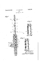
F 1 is a sectional elevation of one form of my improved whorl;
Fig. 2 is a sectional elevational view of the i whorl pulley before assembly; and
Fig. 3 is a sectional elevational view of a whorl pulley of modified construction.
Referringto the drawings in detail and first of all to Figs. 1 and 2, l designates a whorl spindle rotatable vertically in a fixed bearing 2. This bearing is providedwith a lateral extension or bracket 3 carrying a pivoted latch arm 4 provided for latching the whorl in its bearing.
5 designates the whorl pulley which is made Vfrom bar stock of substantially the Y same diameter as the desired finishedbody diameter therebyreducing the. cost of finishing to a minimum. The lower end of the. whorl body 6 is threaded as shown at 7 so as 1930. Serin No. 445,269.
to receive an internally threaded removable flange ring 7 v .The body portion 6of the whorl pulley is straight sided and is bored longitudinally for pai-tof its length as shown at 8 to receive l' extension 9 of the bearing 2,'the remainder of the bodyportionbeing 'providedv with a f reduced taperedlongitudinal bore 10 to receive the spindle 1, which from the pointy 11 to the upper end rkof the spindle is tapered so as *to frictionally hold the pulley thereto to4 provide a drive for the'spindle, and to frictionally hold the bobbin 12 on'the spindle for rotating therewith.
In operation a beltengages the bodyfportion 6 of the whorl pulley to rotate the whorl and the bobbin. y i In removing the empt bobbin fromthe tapering spindle lj the bobb to yhave become stuck on the spindle in which event it may be given a sharp blow with a mallet vor other` suitableinstrument so as to free it fro-1n 'the spindle. In striking 'the bobbin the whorl may moveupwardly so that theliange ring 7 vstrikes thelatch L.twith a quick impact. :In previous constructions the whorl pulleys have been one piece cast iron structures -and under the'conditions just outin may' be found lined the flange-ring aften is chipped and v the whorl thereby rendered useless, not only causing shutdown but necessitating substitution of a new whorl. By my construction, however, while chipping of the flange is a very remote possibility, shouldl the flange ring 7 become chipped itjisa simple matter to remove'the ring `andto replace it with a new one.
It will be seen, therefore, from the foregoing that my improved construction provides a whorl, the body of which is made from bar stock substantially the same diameter as the required finished diameter with a flange of largerV diameter than the b dy removably secured thereto.
In Fig.: 3 I have provided a construction similar to that just described except in that the lower end of the body portion 6 which receives the flange ring 7 f is spun over so as to hold the flange ring in place when assembled.
By constructing the whorl pulley iny two pieces which are removably secured to each other and by employing cold rolled steel, for example, in my construction, not only do I effect a saving in cost of manufacture but I effect a saving to the consumer in that When the Whorl flange is broken or chipped the same may be readily replaced Without requiring him to go to the expense of replacing the entire Whorl pulley.
'1. A 'Whorl for spindles comprising an elongated cylindrical body portion, the upper end of the body portion being bored for the reception of a spindle, the remainder of 15 the body portion being bored longitudinally tofreceive a spindle bea-ring, and a flange for the body portion of greater outside diameter than .the outside diameter of the body `portion and removably secured to the exterior of'tlie lower end of the body portion.
2. A spindle Whorl comprising an elongated cylindrical body portion of round bar stool; of substantially the same diameter as the finished body diameter, lsaid body por tion being bored `at its upper end to provide for the reception of a spindle, the remainder ofthe vbody portion of the Whorl being bored longitudinally Yto freely receive a spindle bearing, and a'flange ring of larger outside v diameter than the body portion of the Whorl removably carried on the outside of the lower end of 'the Whorl. I
.3. A spindle Whorl comprising a cylindrical"elongatedbody portion bored at its upper end to receive a spindle, the remainder ofthe body lortion of the Whorl being bored longitudinal Ito freely receive a spindle bearing and a ange ring of larger outside diameter than the body portion, threaded 10 upon the lower-end of the said body portion. This specification signed this 10th day of March, '1980. Y l
` OTTO W. SCHAUM.
Priority Applications (1)
| Application Number | Priority Date | Filing Date | Title |
|---|---|---|---|
| US445269A US1851686A (en) | 1930-04-18 | 1930-04-18 | Whorl |
Applications Claiming Priority (1)
| Application Number | Priority Date | Filing Date | Title |
|---|---|---|---|
| US445269A US1851686A (en) | 1930-04-18 | 1930-04-18 | Whorl |
Publications (1)
| Publication Number | Publication Date |
|---|---|
| US1851686A true US1851686A (en) | 1932-03-29 |
Family
ID=23768235
Family Applications (1)
| Application Number | Title | Priority Date | Filing Date |
|---|---|---|---|
| US445269A Expired - Lifetime US1851686A (en) | 1930-04-18 | 1930-04-18 | Whorl |
Country Status (1)
| Country | Link |
|---|---|
| US (1) | US1851686A (en) |
-
1930
- 1930-04-18 US US445269A patent/US1851686A/en not_active Expired - Lifetime
Similar Documents
| Publication | Publication Date | Title |
|---|---|---|
| US2251031A (en) | Drawing roll coupling | |
| US1851686A (en) | Whorl | |
| CN105088446A (en) | Steel ring for spinning machine | |
| US1957860A (en) | Spinning bobbin | |
| US2220006A (en) | Spindle for strand wrapping | |
| US1265924A (en) | Spinning-ring and method of forming the same. | |
| US2555652A (en) | Spinning and twisting spindle | |
| US1372844A (en) | Spinning-ring and ball-bearing traveler therefor | |
| US2558210A (en) | Spinning spindle | |
| US651702A (en) | Spinning apparatus. | |
| US2517920A (en) | Spindle of yarn spinning machines | |
| US1660073A (en) | Reel for silk-winding machines | |
| US2197530A (en) | Traveler device | |
| US3216185A (en) | Flyer frame construction | |
| US1240803A (en) | Spinning-machine spindle. | |
| GB191025611A (en) | Improvements in Creel Spindles or Skewers for Machinery for Preparing, Spinning and othwerwise Treating Fibrous Substances. | |
| CN107954277A (en) | A kind of Novel textile bobbin | |
| US2146849A (en) | Fan traveler | |
| US2024448A (en) | Cap for spinning or twisting machines | |
| US1656747A (en) | Mill nut | |
| US580723A (en) | Spindle | |
| GB328251A (en) | Improvements in flyers for spinning, doubling, twisting and like machines | |
| US2089933A (en) | Driving device for a centrifugal spinning machine | |
| US240731A (en) | Ring-spinning frame | |
| US795476A (en) | Spinning or twisting machine. |