US1851633A - Fastening device - Google Patents
Fastening device Download PDFInfo
- Publication number
- US1851633A US1851633A US517725A US51772531A US1851633A US 1851633 A US1851633 A US 1851633A US 517725 A US517725 A US 517725A US 51772531 A US51772531 A US 51772531A US 1851633 A US1851633 A US 1851633A
- Authority
- US
- United States
- Prior art keywords
- pad
- furniture
- cup
- head
- slot
- Prior art date
- Legal status (The legal status is an assumption and is not a legal conclusion. Google has not performed a legal analysis and makes no representation as to the accuracy of the status listed.)
- Expired - Lifetime
Links
- 239000000463 material Substances 0.000 description 4
- 239000002184 metal Substances 0.000 description 3
- 238000010276 construction Methods 0.000 description 2
- 230000001788 irregular Effects 0.000 description 1
- 238000000465 moulding Methods 0.000 description 1
- 230000000284 resting effect Effects 0.000 description 1
- 230000000717 retained effect Effects 0.000 description 1
Images
Classifications
-
- A—HUMAN NECESSITIES
- A47—FURNITURE; DOMESTIC ARTICLES OR APPLIANCES; COFFEE MILLS; SPICE MILLS; SUCTION CLEANERS IN GENERAL
- A47C—CHAIRS; SOFAS; BEDS
- A47C7/00—Parts, details, or accessories of chairs or stools
- A47C7/002—Chair or stool bases
-
- A—HUMAN NECESSITIES
- A47—FURNITURE; DOMESTIC ARTICLES OR APPLIANCES; COFFEE MILLS; SPICE MILLS; SUCTION CLEANERS IN GENERAL
- A47B—TABLES; DESKS; OFFICE FURNITURE; CABINETS; DRAWERS; GENERAL DETAILS OF FURNITURE
- A47B91/00—Feet for furniture in general
- A47B91/04—Elastic supports
Definitions
- rlhis invention relates to improvements in furniture pads.
- One of the objects of the present invention is the provision of an improved type of furniturepad which is applicable to chairs, tables, or any other piece of furniture, or the like, where a buer pad is desirable to protect the furniture, as well as the woodwork.
- Another object of the present invention is the provision of a furniture pad, the body of which is of rubber, felt, or any other similar yieldable material, and has embodied therein a retaining plate provided with a central opening and a tangent slot whereby the head of a fastening element can be engaged with the slot and ⁇ turned around beneath the plate and then connected with the furniture orl woodwork, as the case may require.
- a still further object of the invention is the provision of a furniture pad, wherein the element which isl used for connecting the pad to the furniture or woodwork is so attached i to the pad as to become a permanent part thereof, although the pad and the fastening elements are ordinarily two separate members, thus when the pad is attached to the bot- Y toni of a chair leg, or table leg, or to other pieces of furniture, the pad is permanently retained in position and cannot be removed until it is desired to replace the same with a new pad.
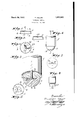
- Figure l is a detailed section on the line 1-1 of Figure 3, illustrating the metal cup or retaining plate;
- Figure 2 is a detailed section on the line 2-2 of Figure l;
- Figure 3 is a plan view of the retaining plate, with parts thereof broken away and illustrated in cross section;
- FIG. 4 is an enlarged detailed section on the line 4-4 of Figure 6, with parts of the article to which the devicev is attached shown in elevation;
- Figure 5 is a bottom plan view of the retaining. members showing the relative position of the head of the attaching member;
- Figure 6 is a side elevation illustrating the pad in applied position;
- Figure 7 is a top plan View of one oft-he'- Vretaining cups illustrating a slight-ly'modifiedform of the'invention;
- ⁇ and- Figure 8 is a side elevation of the lower endV of the chair or table leg illustrating another'form of the invention.
- Y As a general rule furniture pads such vas illustrated in the accompanying' drawings,
- PATENT OFFICE are detachably connected to the i' article to Y which they are to be applied and in a great many instances become loosened and detached' from the article.
- my device comprises a pad which after'bein'g attached to the article of furniture ispeinianently secured in position lso that it will,
- l indicates the lower portionof what might be a-tableor chair leg.
- the pad includes a body 2y which may be of rubber, felt', ⁇
- thel retaining cup 5 is preferably molded intow the body of the pad, as shown in Figure '4: l
- This cup includes aYV body having anoutstanding annular irregular flange 6 which isV embedded in the material, as shown in Figure 4, to securely retain the cupfin ⁇ posi-v ,p
- the pads 2 and the cup members 5, as well as the plates 7 are arranged inposition during the molding of the pad, so that the pad can be placed upon the market with the cup nasi; shownzin-Fignre 3f andfthe.'v shank :of ⁇ the .ifastening-element indicatedrzat 14 will be reused, but said elements must be provided ⁇ with a head, a portion of which is rounded 5 as indieated'at 10 in Figure 5, while one side thereofl is provided with straight cross portion-11l which lies parallel with the exterior surface. ofthe fastening element.
- the cup-shaped body 5 is provided ,with
- this slot is bent'downwardly slightly, "as shown at 13, so that one corner'ofthe ⁇ head 10 can beengaged beneath the bottom of the cup and by turning'the-head,;the-head 'twill ⁇ vbe engaged beneath the bottom ofthe cup a tangent slot 12 and the metal at one side of manufactured at acomparatively low cost.
- a furniture pad including a yieldable H4 ⁇ body and af-retaining-iplate engaged therewith having a central opening, and a slot tangent to the opening and communicating ⁇ therewith.
- i.f[n'SFi-guref.1 8, :"Ii have illustrated @another l 45.::formrof-the .inventioniwherein 'the-culol memfberayis providedv with a laterallv'v disposed flange provided with aplura'lity-f1 of saudable kmay have embedded"therein ⁇ i at cup-shaped member such :.aseindicat'edrA Ain v-the preferred formi'ofithezinventionuand a fastening ele- -f55f-.Inent1nay'ebe engaged withy a. ⁇ 'chair or :table @leg v ⁇ orl similar'l piece of furniture.
Landscapes
- Furniture Connections (AREA)
Description
s. KELAR March 29, 1932.
FASTENING DEVICE Filed Feb. 24, 1931 Patented Mar. 29, 1932 STANISLAW KIELAR, F MILWAUKEE, WISCONSIN,
FASTENING DEVICE Application sied February 24, 193i. serial No. 517,725(
rlhis invention relates to improvements in furniture pads.
One of the objects of the present invention is the provision of an improved type of furniturepad which is applicable to chairs, tables, or any other piece of furniture, or the like, where a buer pad is desirable to protect the furniture, as well as the woodwork.
Another object of the present invention is the provision of a furniture pad, the body of which is of rubber, felt, or any other similar yieldable material, and has embodied therein a retaining plate provided with a central opening and a tangent slot whereby the head of a fastening element can be engaged with the slot and `turned around beneath the plate and then connected with the furniture orl woodwork, as the case may require.
A still further object of the invention is the provision of a furniture pad, wherein the element which isl used for connecting the pad to the furniture or woodwork is so attached i to the pad as to become a permanent part thereof, although the pad and the fastening elements are ordinarily two separate members, thus when the pad is attached to the bot- Y toni of a chair leg, or table leg, or to other pieces of furniture, the pad is permanently retained in position and cannot be removed until it is desired to replace the same with a new pad. l y With the above and other objects in view, the invention consists in the novel features of construction, the combination and arrangement of parts hereinafter more fully set forth, pointed out in the claimsand shown in the accompanying drawings wherein:
Figure l is a detailed section on the line 1-1 of Figure 3, illustrating the metal cup or retaining plate;
Figure 2 is a detailed section on the line 2-2 of Figure l; and,
Figure 3 is a plan view of the retaining plate, with parts thereof broken away and illustrated in cross section;
Figure 4 is an enlarged detailed section on the line 4-4 of Figure 6, with parts of the article to which the devicev is attached shown in elevation;
5 Figure 5 is a bottom plan view of the retaining. members showing the relative position of the head of the attaching member; Figure 6 is a side elevation illustrating the pad in applied position;
Figure 7 is a top plan View of one oft-he'- Vretaining cups illustrating a slight-ly'modifiedform of the'invention; `and- Figure 8 is a side elevation of the lower endV of the chair or table leg illustrating another'form of the invention. Y As a general rule furniture pads such vas illustrated in the accompanying' drawings,
PATENT OFFICE are detachably connected to the i' article to Y which they are to be applied and in a great many instances become loosened and detached' from the article. In the present instance, my device comprises a pad which after'bein'g attached to the article of furniture ispeinianently secured in position lso that it will,
be necessary to destroy the pad before the same can be removed.
Referring more particularly to thedrawings', l indicates the lower portionof what might be a-tableor chair leg. The pad includes a body 2y which may be of rubber, felt',`
or any other suitable material which will not mark or scratch they furniture or the floor on which the same is resting, and the outer surface thereof is arcuate, as' shown at 3 with a substantially flat face 4 adapted" to be fitted against the article to which the device is to be applied.
' In thepresent construction of the pad, thel retaining cup 5 is preferably molded intow the body of the pad, as shown in Figure '4: l
This cup includes aYV body having anoutstanding annular irregular flange 6 which isV embedded in the material, as shown in Figure 4, to securely retain the cupfin `posi-v ,p
tion.. Beneath the bottom of the cup is a'v bearing plate 7 preferably'curved as shown in Figure 4, so that the head 8 of the fastening element 9 will be disposed between the bottom ofthe cup and the bearing plate 7 andnot engage the material of which the pad is formed.
The pads 2 and the cup members 5, as well as the plates 7 are arranged inposition during the molding of the pad, so that the pad can be placed upon the market with the cup nasi; shownzin-Fignre 3f andfthe.'v shank :of `the .ifastening-element indicatedrzat 14 will be reused, but said elements must be provided` with a head, a portion of which is rounded 5 as indieated'at 10 in Figure 5, while one side thereofl is provided with straight cross portion-11l which lies parallel with the exterior surface. ofthe fastening element.
The cup-shaped body 5 is provided ,with
this slot is bent'downwardly slightly, "as shown at 13, so that one corner'ofthe` head 10 can beengaged beneath the bottom of the cup and by turning'the-head,;the-head 'twill` vbe engaged beneath the bottom ofthe cup a tangent slot 12 and the metal at one side of manufactured at acomparatively low cost.
`While I have shown and described the preferred embodiment of my invention, it will be apparent from the foregoing thatr slight changes may be made in the construction` when putting the invention into practice without departing from the spirit. ofthe saine` orlthe sco-peof the appended zolaims. I claim Y 1. A furniture pad including a yieldable H4`body and af-retaining-iplate engaged therewith having a central opening, and a slot tangent to the opening and communicating` therewith.
2. A furniture pad neming a yieidabie 'cup-shaped bodyY having fan wangularly.-A disposed flange, a yieldable bodyeembra-eing the '-#20-fplaoed::inlapositionythe metal 13 lIhas -a` -ten- ,iivedwithin Central -Openingjnthe bot` Amay' or port-ifonzof the cup; andthe flange; and
tom of the ouprl-finfterithehead fhas been.k
ingand a-slot tangent tothe .opening andeemlmunicatingtherewith. f y
' 3A furniture padincluding avyieldable body, a :retaining plate engagedtherewith, Y having a1 centrall opening,iand-a -slotftangent L elenoyr,-toigspring4 upwardly so't'hat it.` twill-be; Y impossible .itoafreturr'r the ghead..bacl 2 \through fathe slot y12;.vandf the pad can. be fsecured to .:wthe'abottomfiiof afehair. or :table-le,f ;,n=o1" any 5 other suitablewarticle by. meansofathelfasnftenifn-g element; whichfrnay; be -amai1,scre w,-. f :or ithelike.
'Itwill bei apparent'that byi embedding ythe and a rfastening elemen-thavingaheadformed engagez saidY slot whereby the .he'adwe-an be said `cupeshafped body having a central openv to the opening and.coinmunieati-ngtherewith-f;
^ c with ar-straight zface to `provide-iportiens to y #Cup 5 withintheipads 2;fthe1pads'.`can= be sold 0., separately, buta it is ,preferable-tov eonnectthe rzrfastenina'f :elem entsv therewith before the same z gfiszplaceids on vi the market. However; the -fas- 2 f "vislotiril: lis aformfedr. in .the b'ottonfnv of the cup or Jaretaining: .plate `andfthehead :of the'` fasten- 1 --ingl element may :befreadily:engaged;within 401`this2slo-tvandi turned` aroun'diuntil al1. `of thel communicating with the opening, and a fastening element having a. head formedfvwith 1 -ar-strai'ght facev=to :providev portions. `to/engage Vsaid slot whereby the head; vcan-1 bere- '5 moved-beneaththeiplate.
.iheadri'sipassedi out'ithei 'other side of thefplate.
-fThai-shanlrQifwilliathentfituinto the. central f :nop eningafasy y'i llustratfed. f
i.f[n'SFi-guref.1 8, :"Ii have illustrated @another l 45.::formrof-the .inventioniwherein 'the-culol memfberayis providedv with a laterallv'v disposed flange provided with aplura'lity-f1 of vieldable kmay have embedded"therein` i at cup-shaped member such :.aseindicat'edrA Ain v-the preferred formi'ofithezinventionuand a fastening ele- -f55f-.Inent1nay'ebe engaged withy a. `'chair or :table @leg v`orl similar'l piece of furniture.
It E'will :befA apparent ;V from -5 the foregoing 'Y eocpadfwherein anfasteningf ,element may be iatvtached thereto and then permanentlysconi n-ected tto the-bottomof ,the chair; orftablev leg, .von'similarloeation, -where a-padof v:this charlg.,aeter:iw-ould.be required. .The ,fpad itself is --35 4extremerlysirnple fn eonstructiom and lfean vbe f moved 'beneath the plate.
4, A .furniture nadf'inoluding ajiyifeldableh body; a retaining plate engagedfltherewith, having af central opening-and afslot-eommunieating the`rew;ith,:-` and.l a. `fastening-element .ih'avingna V:head formed; with .a straight" face v.to provide port-ions tofengageysai-dslotwhere-f g f by the 1 heady i can! be; moved beneath the gplate.
J 5. furniture:pad'eincludingr ayi;eldable body, aretaining plate:havingy its major portion. embedded zinthe bodysaid retaining platev having a Centralopening-andiafslot In testimony that I claim the foregoing- I :have :hereunto set; my l hand at ,Milwaulree, in
the county 1 of :Milwaukee and `State -of' Wis- ,erm-N.isLAwminata.`
Priority Applications (1)
| Application Number | Priority Date | Filing Date | Title |
|---|---|---|---|
| US517725A US1851633A (en) | 1931-02-24 | 1931-02-24 | Fastening device |
Applications Claiming Priority (1)
| Application Number | Priority Date | Filing Date | Title |
|---|---|---|---|
| US517725A US1851633A (en) | 1931-02-24 | 1931-02-24 | Fastening device |
Publications (1)
| Publication Number | Publication Date |
|---|---|
| US1851633A true US1851633A (en) | 1932-03-29 |
Family
ID=24060970
Family Applications (1)
| Application Number | Title | Priority Date | Filing Date |
|---|---|---|---|
| US517725A Expired - Lifetime US1851633A (en) | 1931-02-24 | 1931-02-24 | Fastening device |
Country Status (1)
| Country | Link |
|---|---|
| US (1) | US1851633A (en) |
Cited By (1)
| Publication number | Priority date | Publication date | Assignee | Title |
|---|---|---|---|---|
| USD548576S1 (en) * | 2003-10-16 | 2007-08-14 | Bushey Richard D | Self-adjusting furniture glide |
-
1931
- 1931-02-24 US US517725A patent/US1851633A/en not_active Expired - Lifetime
Cited By (1)
| Publication number | Priority date | Publication date | Assignee | Title |
|---|---|---|---|---|
| USD548576S1 (en) * | 2003-10-16 | 2007-08-14 | Bushey Richard D | Self-adjusting furniture glide |
Similar Documents
| Publication | Publication Date | Title |
|---|---|---|
| US2107629A (en) | Adjustable chair leg extension | |
| US2343287A (en) | Antidrip device | |
| US998996A (en) | Attachment for invalid-beds. | |
| US2188844A (en) | Bedpan cushion | |
| US2061664A (en) | Sanitary crepe rtjbber cushion | |
| US1851633A (en) | Fastening device | |
| US2212780A (en) | Billiard cue | |
| US771679A (en) | Furniture-pad. | |
| US1804437A (en) | Combination shoe and glide for furniture | |
| US2625986A (en) | Table for detachable connection to chairs | |
| US1221225A (en) | Floor-protecting attachment for furniture. | |
| US2956850A (en) | Table leg joint connection | |
| US1604293A (en) | Sliding caster | |
| US1229226A (en) | Dish attachment. | |
| US1651000A (en) | Removable foot for legs | |
| US1423700A (en) | Locking means for caster pintles | |
| US1693022A (en) | Cover-clamping means for bedsteads | |
| US1152235A (en) | Furniture-pad. | |
| USD121154S (en) | Design for a container server top or similar article | |
| USD124058S (en) | Design for a sprayer or similar article | |
| USD190555S (en) | Elevated toilet seat | |
| USD105010S (en) | Design for a sofa or similar article | |
| USD90559S (en) | Design for a wooden bed | |
| USD121576S (en) | Design for a corn pad or the mke | |
| USD99802S (en) | Design for a swivel chair |