US1851544A - Mud ring - Google Patents
Mud ring Download PDFInfo
- Publication number
- US1851544A US1851544A US448585A US44858530A US1851544A US 1851544 A US1851544 A US 1851544A US 448585 A US448585 A US 448585A US 44858530 A US44858530 A US 44858530A US 1851544 A US1851544 A US 1851544A
- Authority
- US
- United States
- Prior art keywords
- mud ring
- mud
- ring
- members
- tubes
- Prior art date
- Legal status (The legal status is an assumption and is not a legal conclusion. Google has not performed a legal analysis and makes no representation as to the accuracy of the status listed.)
- Expired - Lifetime
Links
- 230000003137 locomotive effect Effects 0.000 description 4
- XLYOFNOQVPJJNP-UHFFFAOYSA-N water Substances O XLYOFNOQVPJJNP-UHFFFAOYSA-N 0.000 description 3
- 238000010276 construction Methods 0.000 description 1
- 239000007789 gas Substances 0.000 description 1
- 238000007689 inspection Methods 0.000 description 1
Images


Classifications
-
- F—MECHANICAL ENGINEERING; LIGHTING; HEATING; WEAPONS; BLASTING
- F22—STEAM GENERATION
- F22B—METHODS OF STEAM GENERATION; STEAM BOILERS
- F22B13/00—Steam boilers of fire-box type, i.e. boilers where both combustion chambers and subsequent flues or fire tubes are arranged within the boiler body
- F22B13/06—Locomobile, traction-engine, steam-roller, or locomotive boilers
- F22B13/10—Locomobile, traction-engine, steam-roller, or locomotive boilers with auxiliary water tubes inside the fire-box
- F22B13/12—Locomobile, traction-engine, steam-roller, or locomotive boilers with auxiliary water tubes inside the fire-box the auxiliary water tubes lining the fire-box
Definitions
- the present invention relates to locomotive mud rings and more particularly to structures of this kind intended for use in con-x nection with locomotive fire boxes comprising. walls built up of vertical water tubes.
- the object of the invention is toprovide a mud ring of this type of 'an improved construction.
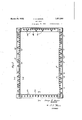
- Fig. 1 is a lateral elevation ofthe rear end of the locomotive boiler having a mud ring in accordance with my invention, portions being broken away;
- Fig. Q' is a plan view of my improved mud ring, no tubes being shown in place:
- Fig. 3 is an end elevation of the mud ring;
- Fig. 4 is a section on line Jr-4E of Fig. 2.;
- Fig.5 is a section on line 5-5 of Fig. 2;
- Fig. 6 is a plan view of a corner of the mud ring showing some details, portionsbeing broken out to illustrate others behind them;
- Fig. 7 is a sectional view on line 7- 7 of Fig. 6.
- Fig. 8 is a sectional view on line 8-8 of Fig. 6.
- Figs. 4 to 8 are on an en larged scale as compared with the first three figures.
- the mud ring is made up of four separate members. Two of these, 1a and 16, run parallel to the longitudinal axis of the locomotive boiler, the other two, 2a and 2?), being disposed at right-angles to the former.
- Thefour members are rectangular in external outline and have extending through them acylindrical cavity. This cavity in each case I extends through the member from end to end.
- the upper surface of the members is pro: vided with holes to receive the lower ends of the vertical water tubes.
- the rear header 2a for example, there is a line of holes 20.
- the lateral members 1a and 15' each have an inner row of openings lc and a series of outer openings 1d.
- the open ings 1c are expanded'the' lower ends of bifurcated tubular elements3 3. These elements are in contact with each other and form a sub; stantially continuous lateral wall .on' each" sideof the furnace.
- Theopenings'1d1d'rer exactly corresponding fashion.
- drical portion is shown at 8 and it extends through a correspondingly shape'dbpening through the member 1a. 7
- the member 1a hasja 11 of the member 2a seats, the seat extending around the opening in member 1a. -Along the line 12forming the-outer circumference of the seat the two'm ember's are welded to-- gether to'make a tight jointg
- Theouter end- I of the openingthrough-member;1a is outwardly flared as at 13. The "endll of. the
- opening through the member 2a is interiorly threaded to receive a correspondingly thread ed plug.
- This plug when pulled in with the proper amount of force expands the/end of the member 2a against ,thesides of the cirioo eular opening in the member 141. .At 15 there .is a circumferential weld of the circular end of member 2a to member 1a to make a tight 7 joint.
- A- loeomotive zm-ud ring comprising four elongated members each having a-longitudinalcavityextendingcfromien'dto end -said .me'm-bers being arranged to form a rectangle
Landscapes
- Engineering & Computer Science (AREA)
- Chemical & Material Sciences (AREA)
- Combustion & Propulsion (AREA)
- Physics & Mathematics (AREA)
- Thermal Sciences (AREA)
- Mechanical Engineering (AREA)
- General Engineering & Computer Science (AREA)
- Coke Industry (AREA)
Description
. March 29, 1932. I H. B. BOWEN 1,851,544
MUD RING F d April 50, 1930 3 Sheets-Sheet 1 INVENTOR ATTORN EY March 29, 1932.
March 29, 1932.
H. B, BOWEN MUD RING Filed April 30, 1930 3 Sheets-Sheet 5 INVENTOR BY Q/JIQQ ATTORNEY Patented Mar. 29, 1932 UNITED STATES HENRY B. BowEruoF Mommas; onE A QA fi o 7 COMPANY, or New YQBK, N,
MUD, rims App lication filed April 30,
The present invention relates to locomotive mud rings and more particularly to structures of this kind intended for use in con-x nection with locomotive fire boxes comprising. walls built up of vertical water tubes.
i The object of the invention is toprovide a mud ring of this type of 'an improved construction. i
The invention is illustrated in the drawings accompanying this specification. In the drawings, Fig. 1 is a lateral elevation ofthe rear end of the locomotive boiler having a mud ring in accordance with my invention, portions being broken away; Fig. Q'is a plan view of my improved mud ring, no tubes being shown in place: Fig. 3 is an end elevation of the mud ring; Fig. 4 is a section on line Jr-4E of Fig. 2.; Fig.5 is a section on line 5-5 of Fig. 2; Fig. 6 is a plan view of a corner of the mud ring showing some details, portionsbeing broken out to illustrate others behind them; Fig. 7 is a sectional view on line 7- 7 of Fig. 6. and Fig. 8 is a sectional view on line 8-8 of Fig. 6. Figs. 4 to 8 are on an en larged scale as compared with the first three figures. I
The mud ring, as will be seen clearly from an inspection of Fig. 2, is made up of four separate members. Two of these, 1a and 16, run parallel to the longitudinal axis of the locomotive boiler, the other two, 2a and 2?), being disposed at right-angles to the former. Thefour members are rectangular in external outline and have extending through them acylindrical cavity. This cavity in each case I extends through the member from end to end.
The upper surface of the members is pro: vided with holes to receive the lower ends of the vertical water tubes. In the rear header 2a, for example, there is a line of holes 20. Into these aree-xpandedthe lower ends of vertical tubes which formthe back wall of the furnace. The lateral members 1a and 15' each have an inner row of openings lc and a series of outer openings 1d. Into the open ings 1c are expanded'the' lower ends of bifurcated tubular elements3 3. These elements are in contact with each other and form a sub; stantially continuous lateral wall .on' each" sideof the furnace. Theopenings'1d1d'rer exactly corresponding fashion.
drical portion is shown at 8 and it extends through a correspondingly shape'dbpening through the member 1a. 7
portion 8 has formed through one of its sides 1930.. sen-aina asss'x ly behind it) Water to the mud ring is sup- THE surniaune'rnn r ceive the lowerlen'ds of the downcomer tubes pliedr through the downc'omers 4 4.- The' forward mud. ring memberQb has a-s'eries of openings 2d2d into whichare expanded the loweriends of forwardly extending tubes 5 which form the bottom of acombustion chamberathroughwhichthe gases pass after leaving; the fire-box The holes 26 .111 the tubes extending through the fire-box. Access to: thetubeswhich are expanded intothe various openings referred to is-pro- .-vided by corresponding,openings 6 in the opposite wall; of the members 1a,=1 b',2a a nd 2b.
7, expandedior rolledinto them;
both of its ends turned down to a cylinzmember 26 arelfor the connection 0f arch;
This figure, as well as the associated Figs. 7
and 8, shows one of the corners of the mud ring, the other corners being constructed in The cylin:
an opening 9 putting the interior of the member 2a into communication with the interior of the member 1a. plane surface 10 against which a: shoulder The cylindrical.
The member 1a hasja 11 of the member 2a seats, the seat extending around the opening in member 1a. -Along the line 12forming the-outer circumference of the seat the two'm ember's are welded to-- gether to'make a tight jointg Theouter end- I of the openingthrough-member;1a is outwardly flared as at 13. The "endll of. the
opening through the member 2a is interiorly threaded to receive a correspondingly thread ed plug. This plugwhen pulled in with the proper amount of force expands the/end of the member 2a against ,thesides of the cirioo eular opening in the member 141. .At 15 there .is a circumferential weld of the circular end of member 2a to member 1a to make a tight 7 joint. At 16 (Fig. 7) is shown the plug inserted into the end of the openingwhich extends into member la..,=,Both the plug that i closes theop'ening 14 and theipl'ugi '16 are Welded in to insuretightness.
Each of the four corners is constructed. 7
' like the one-described and the resulting strung ture is a rigid and rugged -mud ring. Ae
cess to its interior, for various purposes ,canb readily be had through the removal or the Z plugs vor of the thimbles- 7.
It will be Obvious l ertain modifieetionscould be introduced in practicing the invention without depaatingriromthespiiiit x fethis disclosure" l j and being joined to each other at the "cornets, of the members meeting at 'ea'ch corner having a cylindrical perforation near ,its endintersecting its cavity'tlie perforation ;being=-s1ightly flared fat zits outer side, the v n other member having-its-endcorrespondingly :10
shaped andfitted snugly into said. perform tion and having a'plugscrewed into Tits-end forcing the all against theuflamedjsides of the perforation, asaid second 1 member havingarsquare shoulder bearingaghinstthecorv respondingly'flattenedsideof the"first m'em-v leer-,the cylindrical end nftlre 'second member having a lateral 'opening plafcingthecavities I ost the two members into communimtiomthe the firstamember being closed: :by a
A- loeomotive zm-ud ring comprising four elongated members each having a-longitudinalcavityextendingcfromien'dto end -said .me'm-bers being arranged to form a rectangle
Priority Applications (1)
| Application Number | Priority Date | Filing Date | Title |
|---|---|---|---|
| US448585A US1851544A (en) | 1930-04-30 | 1930-04-30 | Mud ring |
Applications Claiming Priority (1)
| Application Number | Priority Date | Filing Date | Title |
|---|---|---|---|
| US448585A US1851544A (en) | 1930-04-30 | 1930-04-30 | Mud ring |
Publications (1)
| Publication Number | Publication Date |
|---|---|
| US1851544A true US1851544A (en) | 1932-03-29 |
Family
ID=23780892
Family Applications (1)
| Application Number | Title | Priority Date | Filing Date |
|---|---|---|---|
| US448585A Expired - Lifetime US1851544A (en) | 1930-04-30 | 1930-04-30 | Mud ring |
Country Status (1)
| Country | Link |
|---|---|
| US (1) | US1851544A (en) |
-
1930
- 1930-04-30 US US448585A patent/US1851544A/en not_active Expired - Lifetime
Similar Documents
| Publication | Publication Date | Title |
|---|---|---|
| US1851544A (en) | Mud ring | |
| US1741121A (en) | Manufacture of boilers | |
| US1514685A (en) | Locomotive boiler | |
| US1686893A (en) | High-pressure steam boiler for locomotives | |
| US1981895A (en) | Boiler | |
| US1405346A (en) | Method of maktiteactubing | |
| US1704624A (en) | neebe | |
| US1652188A (en) | George carl vennttm | |
| US1941268A (en) | Boiler | |
| US1737757A (en) | Metallic baffle | |
| US1618829A (en) | Boiler | |
| US1008526A (en) | Water-tube boiler. | |
| US1787730A (en) | Steam-boiler connection | |
| GB316155A (en) | Method of fitting boiler tubes into tube plates | |
| US964300A (en) | Fire-box. | |
| US943916A (en) | Steam-generator. | |
| USD70167S (en) | Design for an ash receiver | |
| US1813077A (en) | Locomotive boiler | |
| US661868A (en) | Steam-generator. | |
| US1407428A (en) | Radiator | |
| US2356264A (en) | Locomotive boiler firebox | |
| US1308102A (en) | Planograph co | |
| US1704144A (en) | Method of repairing siphons | |
| US275787A (en) | Steam-boiler | |
| US1049140A (en) | Circulating-tube for steam-boilers. |