US1851524A - Window sash - Google Patents
Window sash Download PDFInfo
- Publication number
- US1851524A US1851524A US445282A US44528230A US1851524A US 1851524 A US1851524 A US 1851524A US 445282 A US445282 A US 445282A US 44528230 A US44528230 A US 44528230A US 1851524 A US1851524 A US 1851524A
- Authority
- US
- United States
- Prior art keywords
- sash
- frame
- window sash
- window
- fastening
- Prior art date
- Legal status (The legal status is an assumption and is not a legal conclusion. Google has not performed a legal analysis and makes no representation as to the accuracy of the status listed.)
- Expired - Lifetime
Links
- MXBCYQUALCBQIJ-RYVPXURESA-N (8s,9s,10r,13s,14s,17r)-13-ethyl-17-ethynyl-11-methylidene-1,2,3,6,7,8,9,10,12,14,15,16-dodecahydrocyclopenta[a]phenanthren-17-ol;(8r,9s,13s,14s,17r)-17-ethynyl-13-methyl-7,8,9,11,12,14,15,16-octahydro-6h-cyclopenta[a]phenanthrene-3,17-diol Chemical compound OC1=CC=C2[C@H]3CC[C@](C)([C@](CC4)(O)C#C)[C@@H]4[C@@H]3CCC2=C1.C1CC[C@@H]2[C@H]3C(=C)C[C@](CC)([C@](CC4)(O)C#C)[C@@H]4[C@@H]3CCC2=C1 MXBCYQUALCBQIJ-RYVPXURESA-N 0.000 description 1
- 241000511343 Chondrostoma nasus Species 0.000 description 1
- 241001417984 Cynoglossidae Species 0.000 description 1
- 101100001674 Emericella variicolor andI gene Proteins 0.000 description 1
- 241000184251 Eresia Species 0.000 description 1
- 241001620634 Roger Species 0.000 description 1
- BFPSDSIWYFKGBC-UHFFFAOYSA-N chlorotrianisene Chemical compound C1=CC(OC)=CC=C1C(Cl)=C(C=1C=CC(OC)=CC=1)C1=CC=C(OC)C=C1 BFPSDSIWYFKGBC-UHFFFAOYSA-N 0.000 description 1
- 238000010276 construction Methods 0.000 description 1
- 239000011521 glass Substances 0.000 description 1
- 230000037431 insertion Effects 0.000 description 1
- 238000003780 insertion Methods 0.000 description 1
Images
Classifications
-
- E—FIXED CONSTRUCTIONS
- E06—DOORS, WINDOWS, SHUTTERS, OR ROLLER BLINDS IN GENERAL; LADDERS
- E06B—FIXED OR MOVABLE CLOSURES FOR OPENINGS IN BUILDINGS, VEHICLES, FENCES OR LIKE ENCLOSURES IN GENERAL, e.g. DOORS, WINDOWS, BLINDS, GATES
- E06B3/00—Window sashes, door leaves, or like elements for closing wall or like openings; Layout of fixed or moving closures, e.g. windows in wall or like openings; Features of rigidly-mounted outer frames relating to the mounting of wing frames
- E06B3/32—Arrangements of wings characterised by the manner of movement; Arrangements of movable wings in openings; Features of wings or frames relating solely to the manner of movement of the wing
- E06B3/34—Arrangements of wings characterised by the manner of movement; Arrangements of movable wings in openings; Features of wings or frames relating solely to the manner of movement of the wing with only one kind of movement
- E06B3/42—Sliding wings; Details of frames with respect to guiding
- E06B3/44—Vertically-sliding wings
- E06B2003/4438—Vertically-sliding wings characterised by the material used for the frames
- E06B2003/4446—Wood
Definitions
- a sash of this character should be vertically movable within the frame, should be capable of operation with the ordinarily employed frames, should be readily removed and replaced, shouldbe simple of operation, economic of construction and free from possible liability in inoperativeness, l
- Figure 1 is a .front view of one form of the device of my invention, the removed position being shown in dot-and-dash lines. v
- FIG. 1 is an enlarged section through the line ⁇ 22 of Figure 1. ⁇
- Figure 3 is an enlarged section through the line 3-3 of Figure l.
- Y f
- Figure 4 is an enlarged section through the I .line 1 -4 of Figure 1.
- Figure 5 is a perspective View of the fastening member.
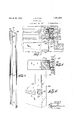
- FIG. 6 is afragmentary perspective vie
- the particular form of the device of my invention, illustrated in the accompanying drawings, consists of a window sash frame having the sides 10and 11, the top 12 and the bottom 13, vertically movable within a Yonlinssieirn To siAiiEajY ⁇ WINIW EYIC?.
- window frame having. ⁇ the-. Y y A l andthe bottom 16. 1', 'j .f .i n, i
- the edge ⁇ carries fai .mee ta'llic plate 2O "which extends :acrossfthe ⁇ ⁇ re.- 4Cess 18.
- L The inner face: 'of Athe side 121 ,has
- the plate portion f 28 has vtWoclit-outs totallovv the passage of the fatellers 21 and 22.
- '1A sashfcord '31 is si Vattached to the'inner. tace of the metallic ele.-
- metallic fastening member is inserte recess 33 inthe ,sashplate 20.
- the outer edge of thesashlongitudinal, reeess .34,V through which-the' sash 00rd 35, PRSSQS, the Cord Bebeng attached tothe iside 10...;
- the edge l0. has a lengua.'
- the framesidegll carries two up# V.Wardly extended hooks39 andl() capable of l insertion beneaththekplates 37V and 38 re- Zspectively.
- the operation ofthe device is as follows Theldeviceis innorma-l position as shown i in' Figure l, and vthe sash anditsattached y fastening member is capable of vertical move.-
- Y Y i It will thus be seen that my invention presents 1a windowv in which the sash can be readily removed and replaced and, in which :Y- i the device" can be incorporated within the usually employed window frames; y Y l f I; Vdo not limit myself to-'the particular size, shap'e,1number or arrangement of'parts f as lthese are given simply as a means for clearly, describing the ldevice of myainvention; Y
- Y wf WhatvI-claim is V1.
- y"a p window sash frame an ⁇ L-shaped cut-out.
- fasteningmemben' a sash vweight carried "by theY other side of said sash frame, said sashy e framek being capable ofpivotal movement from within said-frame andv means forl re movably attachingl said window sash y frame to said fastening membenr f f Y Signed at New York city, in the-county of-New'York and State of: New York, this,
Landscapes
- Engineering & Computer Science (AREA)
- Civil Engineering (AREA)
- Structural Engineering (AREA)
- Wing Frames And Configurations (AREA)
Description
March 29,1932. Z, RUCHlN 1,851,524
WINDOW SASH Filed April 18, 1930 2 Sheets-Sheet l NVENTOR ATTORNEY z. Rucmm 1,851,524
WINDOW SASH Mwah 29, 1932.
. 2 Sheets-Sheet 2 Filed Apil 18,l 195o PMn-M" ATTORNEY similar parts are designated by similar nu- .5 of a lower portion of the sash.
Patented Mar. 29, `1932 l air. eresia creer #was *.EW l eeliPeeemoaereer weer WINDOW SASif Application filedv Apri 18,
: sash would possess many valuablev `features.
A sash of this character should be vertically movable within the frame, should be capable of operation with the ordinarily employed frames, should be readily removed and replaced, shouldbe simple of operation, economic of construction and free from possible liability in inoperativeness, l
rIhe device of my invention possesses all of the above-mentioned, and. other, valuable attributes as will be evident from a consider; ation of my specification and its accompanying drawings. Y
In the accompanying drawings, illustrating one form of the device of my invention,
merals.
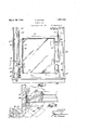
Figure 1 is a .front view of one form of the device of my invention, the removed position being shown in dot-and-dash lines. v
Figure 2 is an enlarged section through the line`22 of Figure 1.`
Figure 3 is an enlarged section through the line 3-3 of Figure l. Y f
Figure 4 is an enlarged section through the I .line 1 -4 of Figure 1.
Figure 5 is a perspective View of the fastening member.
Figure 6 is afragmentary perspective vie The particular form of the device of my invention, illustrated in the accompanying drawings, consists of a window sash frame having the sides 10and 11, the top 12 and the bottom 13, vertically movable within a Yonlinssieirn To siAiiEajY` WINIW EYIC?.
:roger: @meneame y nase.` sensing. 445,232; V l
window frame having.` the-. Y y A l andthe bottom 16. 1', 'j .f .i n, i The outer edge 17 *ofi the? side. 11:- is beveled and-has two recesses 18...;ancll 19 for =.purpose s` n described laterQL The edge `carries fai .mee ta'llic plate 2O "which extends :acrossfthe` `re.- 4Cess 18. L The inner face: 'of Athe side 121 ,has
two slidable fasteninglrneinbers,V4 or plates',l f
21 and 22, slidable'outwardly throughffcut# c .'zffj ff; L f5@ A` detachable,fasteningmembercomprises outsj in the .platef20..
the `wooden `element;2fhaving, alongitudinal recess 24,'andtwo vrecesses 25fand 26c irreV spondin tively@ Y. ,A metallic-platevis"bentinto the'pa-rt .27,
covering the-inner face of the' fastening mem ber,l the ..part28`,.covering `.tlie inner facesof the fastening member is then bent, or folds f ed, upon itself, to form vthe projecti'onf29.,=is
then. bent outwardly forming `.the projection 30 and'then inwardlycovering the outer -f-ace of the fastening member. The plate portion f 28 has vtWoclit-outs totallovv the passage of the fatellers 21 and 22. '1A sashfcord '31 is si Vattached to the'inner. tace of the metallic ele.-
ment 28, extends upwardly through thezre.- cess 24 and carries a weightl (/Iiot-showi-)fin e theframe member 15. 5
w VVhenvinkposition 4for operatiom-theiplate j20=of1the sashfis inserted ,within the-recessY between the projection 129fand-the member-28 .Of theV fastening menib'erjand locked in position `by the fasteners 21 and 22. i
L To lfurtherprevent longitudinal movement 7 of the` sash and fastening n-iember: vwith-frespeet tojeachother, a `pin 32carriedby'tlie y. l
metallic fastening member is inserte recess 33 inthe ,sashplate 20.-
It is to benotedthatfwhen theiiasiteners "21 andI 22 are withdrawm the lsash ,can beurernoved from the fastening` member, whereas., when they are fastened;l together theyk will move longitudinally asa unit within the re"- cess of thewindowframe.l
The outer edge of thesashlongitudinal, reeess .34,V through which-the' sash 00rd 35, PRSSQS, the Cord Bebeng attached tothe iside 10...; The edge l0. has a lengua.'
gto the fasteners-21and-22 respece Sideio his@ haai and 38.` The framesidegll carries two up# V.Wardly extended hooks39 andl() capable of l insertion beneaththekplates 37V and 38 re- Zspectively. l
The operation ofthe device is as follows Theldeviceis innorma-l position as shown i in'Figure l, and vthe sash anditsattached y fastening member is capable of vertical move.-
ment in 'the ordinary manner. Y Vhen it; desired to remove thegwindow, thepm il 1sv linsertedin the yhole 42 of the vframesde yl5,V
i andthe fasteners 21 and22 are withdrawn,
thus freeing the sash from the frame; rlhe sash can then be entirely withdravi/1nfrom the frame, and the sash weight will draw Athe Afastening member upwardlyuntil it con# fr tacts withthe pin 41; 'In order to Lfacilitate the;wash 'ngoperationy of the outer face of the glass carried by the sash,the hooks 39 and40 20 are inserted beneath the platesjf-37fand 38, p y
thus. suspending the' sash, .and as there is only YVsash weight operating,that-is,the one carried bythe cord 35,'there-,will-be no excessive upward `pull upon lthe sash, 'and it can be n readily manipulated; The dot-and-jdash lines in;y the. drawings show. the positionY of the sash in its several withdrawal positions, and
- similar parts in these drawings areshown inprime numerals.' f r Y Y I have shown my devlce as applied .to the y ylower sash ofl a window, but itis'evident that Y is similarly applicable to upper sashes. Y Y i It will thus be seen that my invention presents 1a windowv in which the sash can be readily removed and replaced and, in which :Y- i the device" can be incorporated within the usually employed window frames; y Y l f I; Vdo not limit myself to-'the particular size, shap'e,1number or arrangement of'parts f as lthese are given simply as a means for clearly, describing the ldevice of myainvention; Y
Y wf WhatvI-claim is V1. In a window sash, .in combination, y"a p window sash frame an `L-shaped cut-out. in
theouter cornerl of one side (of said sash thel outer 'edgeface rfr'saidfsash'frame and extending beyond said face, forming va recess with the Wall of said cut-out portion ;V a winr-V dow frame; ajslidableffastening member carried by one side vof said windowv` frame; a metallic plateiixedly attached to fthe ex+ posed face of saidrfastening means, a portionL y Of saidy fasteningrmember being positioned within said recessY and longitudinally'remo.V-v` able therefrom ;v a sash Weight :carried'by Said. fasteningmemben' a sash vweight carried "by theY other side of said sash frame, said sashy e framek being capable ofpivotal movement from within said-frame andv means forl re movably attachingl said window sash y frame to said fastening membenr f f Y Signed at New York city, in the-county of-New'York and State of: New York, this,
15th day'of'April',1930.v i Y l e y ZANYRUGHIN;V
frame; ametall-ic plate fixedly attached tov v theouterzied'geface of said/sash frame and Y i extending beyond said-face, forming-a recess with the wall of ysaid cut-out portion; ay win-V dow frame a slidable fastening member car-l ried 'by vone 'side of said windowiframe; a?
sash framebeing capable of i 2. In'v a window sash, in combination, :a
window sash frame; anV L-shapedI cut-out ,in
the vouter-.corner of one side of said sash-1,4 frame; a metallic plate 'ffixedly attached to loo
Priority Applications (1)
| Application Number | Priority Date | Filing Date | Title |
|---|---|---|---|
| US445282A US1851524A (en) | 1930-04-18 | 1930-04-18 | Window sash |
Applications Claiming Priority (1)
| Application Number | Priority Date | Filing Date | Title |
|---|---|---|---|
| US445282A US1851524A (en) | 1930-04-18 | 1930-04-18 | Window sash |
Publications (1)
| Publication Number | Publication Date |
|---|---|
| US1851524A true US1851524A (en) | 1932-03-29 |
Family
ID=23768296
Family Applications (1)
| Application Number | Title | Priority Date | Filing Date |
|---|---|---|---|
| US445282A Expired - Lifetime US1851524A (en) | 1930-04-18 | 1930-04-18 | Window sash |
Country Status (1)
| Country | Link |
|---|---|
| US (1) | US1851524A (en) |
-
1930
- 1930-04-18 US US445282A patent/US1851524A/en not_active Expired - Lifetime
Similar Documents
| Publication | Publication Date | Title |
|---|---|---|
| US1851524A (en) | Window sash | |
| FR47149E (en) | extendable prop with punch and closed shaft for support work | |
| US1527739A (en) | Weather strip | |
| FR762500A (en) | Enhanced Profile Side Wing U Iron | |
| FR855671A (en) | Seal for doors, windows and the like | |
| US2537302A (en) | Storm window | |
| FR830902A (en) | Toothed shovel | |
| US1726205A (en) | Corner bracket for frames | |
| US1912533A (en) | Corner metal slide strip | |
| US2174800A (en) | Combination brace and hanger | |
| US2060862A (en) | Cutaway door-window construction | |
| US1704042A (en) | Window construction | |
| US1490701A (en) | Supporting clip | |
| US1434247A (en) | Display-card-rack section | |
| USD110457S (en) | Design for a doorframe | |
| US1883544A (en) | Attachment hook for safety belts | |
| FR843445A (en) | Darkening device, such as curtain or blind | |
| USD110452S (en) | Design for a doorframe | |
| USD107335S (en) | Design for a humidifier | |
| US1311708A (en) | phillips | |
| FR836560A (en) | Pivot panel hung window | |
| US1658709A (en) | Sash-cord holder and connecter | |
| FR680186A (en) | Hinged steel strip curtain | |
| FR870667A (en) | Lock for doors, windows and the like | |
| FR841650A (en) | Safety lock for doors and the like |