US1851481A - Electrode for electrolytic apparatus - Google Patents
Electrode for electrolytic apparatus Download PDFInfo
- Publication number
- US1851481A US1851481A US542140A US54214031A US1851481A US 1851481 A US1851481 A US 1851481A US 542140 A US542140 A US 542140A US 54214031 A US54214031 A US 54214031A US 1851481 A US1851481 A US 1851481A
- Authority
- US
- United States
- Prior art keywords
- electrode
- welded
- parts
- plate
- solution
- Prior art date
- Legal status (The legal status is an assumption and is not a legal conclusion. Google has not performed a legal analysis and makes no representation as to the accuracy of the status listed.)
- Expired - Lifetime
Links
- 239000000243 solution Substances 0.000 description 6
- 230000007797 corrosion Effects 0.000 description 5
- 238000005260 corrosion Methods 0.000 description 5
- XEEYBQQBJWHFJM-UHFFFAOYSA-N Iron Chemical compound [Fe] XEEYBQQBJWHFJM-UHFFFAOYSA-N 0.000 description 4
- 238000003466 welding Methods 0.000 description 4
- 239000003792 electrolyte Substances 0.000 description 3
- 239000008151 electrolyte solution Substances 0.000 description 3
- OQEBBZSWEGYTPG-UHFFFAOYSA-N 3-aminobutanoic acid Chemical compound CC(N)CC(O)=O OQEBBZSWEGYTPG-UHFFFAOYSA-N 0.000 description 2
- FAPWRFPIFSIZLT-UHFFFAOYSA-M Sodium chloride Chemical compound [Na+].[Cl-] FAPWRFPIFSIZLT-UHFFFAOYSA-M 0.000 description 2
- 229910052742 iron Inorganic materials 0.000 description 2
- 238000005868 electrolysis reaction Methods 0.000 description 1
- 230000002101 lytic effect Effects 0.000 description 1
- 230000000630 rising effect Effects 0.000 description 1
- 239000011780 sodium chloride Substances 0.000 description 1
- XLYOFNOQVPJJNP-UHFFFAOYSA-N water Substances O XLYOFNOQVPJJNP-UHFFFAOYSA-N 0.000 description 1
Images
Classifications
-
- C—CHEMISTRY; METALLURGY
- C25—ELECTROLYTIC OR ELECTROPHORETIC PROCESSES; APPARATUS THEREFOR
- C25B—ELECTROLYTIC OR ELECTROPHORETIC PROCESSES FOR THE PRODUCTION OF COMPOUNDS OR NON-METALS; APPARATUS THEREFOR
- C25B11/00—Electrodes; Manufacture thereof not otherwise provided for
- C25B11/02—Electrodes; Manufacture thereof not otherwise provided for characterised by shape or form
Definitions
- the invention relates to an electrode for characterized by the factthat the parts. in which the electrode plate or plates is or are welded to a conducting terminal, are positioned within gas pockets formed below the level of electrolytic solution, and has for its object to prevent the corrosion of the welded parts due to the action of the electrolyte.
- said welded parts are kept within gas pockets formed below the level of the solution.
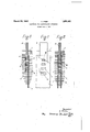
- Fig. 1 is an elevation illustrating a two plate electrode welded to a terminal; Fig. 2 a longitudinal section of the same, and Fig. 3 is a view similar to Fig. 1, showing a single plate electrode.
- gas pockets 4 are formed by suitably arranging iron electrode plates 1 and 2 provided with a series of window holes 5 and an iron terminal 3 with a series of perforations. The upper edges of these gas pockets are welded as shown at W, whereby the electrode plates, and the terminal are made one body. The welding operation may be preferably carried into practice as in the following manner.
- the left upper corners of the perforations formed in the terminal 3 are conveniently Welded to the internal surface of the left hand 'lytic solution.
- the plate 1 by inserting an electrode for electric welding through the windows .5 formed in the right hand plate 2, and alternatively, the right upper corners of the perforations are conveniently welded to the internal surface of the right hand plate 2 by inserting an electrode for the welding through the windows formed in the left hand plate 1.
- F g. 3 shows a single plate electrode, where auxiliary pieces 6 are attached in the positions of perforations opposite to the plate 2.
- the gas pockets 4 are entirely immersed in the electrolytic solution the level of which is shown by It.
- the welded parts W are separated from the electrolyte, and thus the parts W can be effectively protected from corrosion so that the electrode is guaranteed for a considerable long life.
- the invention consists in surround ing the welded parts of electrode plate or plates to the conducting terminal by gas so as to protect the parts from being brought in contact with electrolyte.
- the form of the gas pockets may be modified in various ways without departing from the scope of the lnvention.
- the new electrode according to the invention may be used as positive and negative poles for water electrolyzing apparatus, and also as negative poles for an apparatus of electrolyzing aqueous, solution of sodium chloride, etc.
- An electrode for electrolyzing apparatus characterized by that the parts in which the electrode plate or plates is or are welded to a conducting terminal, are positioned within gas pockets formed below the level of electro- In testimony whereof I KUMEO BABA.
Landscapes
- Chemical & Material Sciences (AREA)
- Engineering & Computer Science (AREA)
- Chemical Kinetics & Catalysis (AREA)
- Electrochemistry (AREA)
- Materials Engineering (AREA)
- Metallurgy (AREA)
- Organic Chemistry (AREA)
- Electrodes For Compound Or Non-Metal Manufacture (AREA)
- Electrolytic Production Of Metals (AREA)
- Electrolytic Production Of Non-Metals, Compounds, Apparatuses Therefor (AREA)
- Sealing Battery Cases Or Jackets (AREA)
- Connection Of Batteries Or Terminals (AREA)
Description
March 29, 1932. K. BABA ELECTRODE FOR ELECTROLYTIC APPARATUS Fi 1ed June 4, 1931 I FJ v avwenitoz'. Baba Gum/mugs electrolytic apparatus,
Patented Mar. 29, 1932 KUMEO BABA, F
HITACHI-MACHI, TAGA-GUN, JAPAN, KAISHA HITACHI SEISAKUSHO, OF TOKYO, JAPAN ASSIGNOR 'ro KABUSHIKI ELECTRODE FOR ELECTROLYTIC APPARATUS Application filed June 4, 1931, Serial No. 542,140, and in Japan June 9, 1930.
The invention relates to an electrode for characterized by the factthat the parts. in which the electrode plate or plates is or are welded to a conducting terminal, are positioned within gas pockets formed below the level of electrolytic solution, and has for its object to prevent the corrosion of the welded parts due to the action of the electrolyte.
r In electrical apparatus, the parts in which the electrode plate is welded to the conductingterminal, when it is immersed directly into the electrolytic solution, are subjected to corrosion far more rapidly than the other parts, and therefore, it is in general to have the electrode to rivet together to the terminal or to position the welded part above the level of the solution. However, both of them accompany great drawbacks, because the riveting operation of the kind is difficult while the positioning of the welded parts above the level of the solution makes the distribution of electric current undesirable.
According to this invention, in order to remove these disadvantages and in order to enable the welded parts to be positioned below the level of the solution without causing corrosion, said welded parts are kept within gas pockets formed below the level of the solution.
In theaccompanying drawings, given solely by way of examples, Fig. 1 is an elevation illustrating a two plate electrode welded to a terminal; Fig. 2 a longitudinal section of the same, and Fig. 3 is a view similar to Fig. 1, showing a single plate electrode.
In Figs. 1 and 2, illustrating an embodi-' ment of two plate electrode, gas pockets 4: are formed by suitably arranging iron electrode plates 1 and 2 provided with a series of window holes 5 and an iron terminal 3 with a series of perforations. The upper edges of these gas pockets are welded as shown at W, whereby the electrode plates, and the terminal are made one body. The welding operation may be preferably carried into practice as in the following manner.
The left upper corners of the perforations formed in the terminal 3 are conveniently Welded to the internal surface of the left hand 'lytic solution.
plate 1 by inserting an electrode for electric welding through the windows .5 formed in the right hand plate 2, and alternatively, the right upper corners of the perforations are conveniently welded to the internal surface of the right hand plate 2 by inserting an electrode for the welding through the windows formed in the left hand plate 1.
F g. 3 shows a single plate electrode, where auxiliary pieces 6 are attached in the positions of perforations opposite to the plate 2.
As will be understood from Figs. 2 and 3, the gas pockets 4: are entirely immersed in the electrolytic solution the level of which is shown by It. By this manner the welded parts W are separated from the electrolyte, and thus the parts W can be effectively protected from corrosion so that the electrode is guaranteed for a considerable long life.
Even if the welding be insuflicient and gas may leak therefrom, the bubbles of gas produced by the course of electrolysis near the parts, or the bubbles rising up along electrodeplate or plates will be accumulated in the pockets until they are filled up with the bubbles so that the parts will be equally protected from corrosion.-
Briefly the invention consists in surround ing the welded parts of electrode plate or plates to the conducting terminal by gas so as to protect the parts from being brought in contact with electrolyte. Of'course the form of the gas pockets may be modified in various ways without departing from the scope of the lnvention.
The new electrode according to the invention may be used as positive and negative poles for water electrolyzing apparatus, and also as negative poles for an apparatus of electrolyzing aqueous, solution of sodium chloride, etc.
. Claim. I a
An electrode for electrolyzing apparatus, characterized by that the parts in which the electrode plate or plates is or are welded to a conducting terminal, are positioned within gas pockets formed below the level of electro- In testimony whereof I KUMEO BABA.
I aflix my signature.
Applications Claiming Priority (1)
| Application Number | Priority Date | Filing Date | Title |
|---|---|---|---|
| JP363289X | 1930-06-09 |
Publications (1)
| Publication Number | Publication Date |
|---|---|
| US1851481A true US1851481A (en) | 1932-03-29 |
Family
ID=12466772
Family Applications (1)
| Application Number | Title | Priority Date | Filing Date |
|---|---|---|---|
| US542140A Expired - Lifetime US1851481A (en) | 1930-06-09 | 1931-06-04 | Electrode for electrolytic apparatus |
Country Status (3)
| Country | Link |
|---|---|
| US (1) | US1851481A (en) |
| DE (1) | DE605575C (en) |
| GB (1) | GB363289A (en) |
Cited By (3)
| Publication number | Priority date | Publication date | Assignee | Title |
|---|---|---|---|---|
| US2474716A (en) * | 1944-09-18 | 1949-06-28 | Submarine Signal Co | Salt-water battery |
| US2761832A (en) * | 1950-08-24 | 1956-09-04 | Crystal Res Lab Inc | Liquid treating apparatus |
| US5512149A (en) * | 1994-09-01 | 1996-04-30 | Mackenna Iv; Gilbert J. | Sacrificial anode device with optimized anode/cathode interface surface contact area |
-
1931
- 1931-06-03 DE DEK120742D patent/DE605575C/en not_active Expired
- 1931-06-04 US US542140A patent/US1851481A/en not_active Expired - Lifetime
- 1931-06-09 GB GB16755/31A patent/GB363289A/en not_active Expired
Cited By (3)
| Publication number | Priority date | Publication date | Assignee | Title |
|---|---|---|---|---|
| US2474716A (en) * | 1944-09-18 | 1949-06-28 | Submarine Signal Co | Salt-water battery |
| US2761832A (en) * | 1950-08-24 | 1956-09-04 | Crystal Res Lab Inc | Liquid treating apparatus |
| US5512149A (en) * | 1994-09-01 | 1996-04-30 | Mackenna Iv; Gilbert J. | Sacrificial anode device with optimized anode/cathode interface surface contact area |
Also Published As
| Publication number | Publication date |
|---|---|
| GB363289A (en) | 1931-12-17 |
| DE605575C (en) | 1934-11-29 |
Similar Documents
| Publication | Publication Date | Title |
|---|---|---|
| US1851481A (en) | Electrode for electrolytic apparatus | |
| GB1257022A (en) | ||
| NO803806L (en) | DEVICE FOR THE ELECTRIC CIRCULATION OF ELECTRICAL CELLS | |
| SE7904873L (en) | ELECTROLYSIS CELL AND WAY TO PRODUCE THE SAME | |
| US1427876A (en) | Apparatus for electrical etching | |
| DK1983D0 (en) | PROCEDURE FOR ELECTROLYSE OF TIN COMPLEXS | |
| US3039950A (en) | Apparatus for electro-chemically removing metal | |
| US1217738A (en) | Battery. | |
| US2069206A (en) | Method and apparatus for recovering precious metal from ore | |
| US3714016A (en) | Aluminum shield for a roll in continuous strip apparatus | |
| US1642550A (en) | Sealing ring | |
| KR850700045A (en) | Electrometallurgical process electrode | |
| US4125448A (en) | Cell and electrodes for electrolytic production of insoluble metal hydroxide | |
| US1365033A (en) | Avalt | |
| US1359716A (en) | Ebhest a | |
| US467350A (en) | Electrolytical plant | |
| US1202149A (en) | Electrolysis of tin and its salts. | |
| US1865216A (en) | Electrode construction | |
| US1398784A (en) | Electrolytic cell | |
| SU39978A1 (en) | The method of obtaining metal niobium by electrolysis | |
| GB299923A (en) | Improvements in and connected with screw propellers and the like | |
| GB381500A (en) | Electrode for electric melting furnaces | |
| US637313A (en) | Apparatus for recutting files by electrolysis. | |
| GB167821A (en) | Improvements in electric accumulators | |
| GB226187A (en) | Method of welding aluminium |