US1851472A - All purpose gate - Google Patents
All purpose gate Download PDFInfo
- Publication number
- US1851472A US1851472A US501363A US50136330A US1851472A US 1851472 A US1851472 A US 1851472A US 501363 A US501363 A US 501363A US 50136330 A US50136330 A US 50136330A US 1851472 A US1851472 A US 1851472A
- Authority
- US
- United States
- Prior art keywords
- gate
- shaft
- gates
- rod
- casing
- Prior art date
- Legal status (The legal status is an assumption and is not a legal conclusion. Google has not performed a legal analysis and makes no representation as to the accuracy of the status listed.)
- Expired - Lifetime
Links
- 238000010276 construction Methods 0.000 description 8
- 230000004888 barrier function Effects 0.000 description 3
- 230000005484 gravity Effects 0.000 description 3
- 230000007246 mechanism Effects 0.000 description 3
- 230000006872 improvement Effects 0.000 description 2
- 238000007665 sagging Methods 0.000 description 2
- 241000283690 Bos taurus Species 0.000 description 1
- 235000008331 Pinus X rigitaeda Nutrition 0.000 description 1
- 235000011613 Pinus brutia Nutrition 0.000 description 1
- 241000018646 Pinus brutia Species 0.000 description 1
- VYPSYNLAJGMNEJ-UHFFFAOYSA-N Silicium dioxide Chemical compound O=[Si]=O VYPSYNLAJGMNEJ-UHFFFAOYSA-N 0.000 description 1
- 230000009471 action Effects 0.000 description 1
- 238000013459 approach Methods 0.000 description 1
- 239000000463 material Substances 0.000 description 1
- 239000002184 metal Substances 0.000 description 1
- 244000144977 poultry Species 0.000 description 1
- 230000003014 reinforcing effect Effects 0.000 description 1
- 230000035939 shock Effects 0.000 description 1
- XLYOFNOQVPJJNP-UHFFFAOYSA-N water Substances O XLYOFNOQVPJJNP-UHFFFAOYSA-N 0.000 description 1
Images


Classifications
-
- E—FIXED CONSTRUCTIONS
- E05—LOCKS; KEYS; WINDOW OR DOOR FITTINGS; SAFES
- E05F—DEVICES FOR MOVING WINGS INTO OPEN OR CLOSED POSITION; CHECKS FOR WINGS; WING FITTINGS NOT OTHERWISE PROVIDED FOR, CONCERNED WITH THE FUNCTIONING OF THE WING
- E05F13/00—Mechanisms operated by the movement or weight of a person or vehicle
- E05F13/04—Mechanisms operated by the movement or weight of a person or vehicle by platforms lowered by the weight of the user
Definitions
- the shaft, outward of itsbearings 5'7, and at the opposite sides of the gate frame 61 has'fixed theretorocker arms 67, the ends of the saidrocker arms having secured thereto compensatlngsprings 'shaft and the stiles of the gate frame, an
Landscapes
- Refuge Islands, Traffic Blockers, Or Guard Fence (AREA)
Description
March 1 c. o. WALKER ET AL 1,851,472
ALL PURPOSE GATE Filed Dec. 10. 1930 s Sheets-Sheet 1 C. 0. WALKEE \MN/ci LMBEAZ/EL 0 g 0 wlTNzss; l$ ATTORNEY March 29; 1932. c. o. WALKER ET AL ALL PURPOSE GATE Filed Dec 1O 1930 6 Sheets-Sheet 2 6'. 0. WALKER & L. M. BEA /EL ATTORNEY WITNESS:
March 29, 1932.
C. O. WALKER ET AL ALL PURPOS E GATE Filed Dec. 10, 1930 6 Sheets-Sheet 4 6'. 0. MLAEE 6 L. M. EEAZ/EL ATTORNEY March 29, 1932. g, o, WALKER ET L 1,851,472
ALL PURPOSE GATE Filed Dec. 10, 1950 6 Sheets-Sheet 5 C. 0. WALKER & L. M. E/EAZ/El.
I INVENTORS BY o w WITNESS: M I ATTORNEY March 29, 1932. c. o. WALKER ET AL 1,851,472
ALL PURPOSE GATE Filed Dec. 10. 1930 6 Sheets-Sheet 6 6? L. M. B/QflZ/EL INVENTORS Patented Mar. 29, 1932 States .onnnnnso vmnxnannn LEVI M. BRAZIEL, ornsn'r; NEW' -MEXICO ALL runrosn GATE Application filed December 10, 1930. Seria1..No.: 501,363.
' "(Durpresent invention has reference to a gate construction and operating means therefor, and our general object is the provision of a gate,'which may be employed at any place where a barrier is desired, and which maybe operated either by a vehicle or by hand'to impart .a partial swinging to the gate to bring the same beyond its center of gravity to permit-the said gate swinging or gravitating to either of its open or closed position and further wherein the gate when approached from one direction is opened and after the pedestrian or vehicle passes the gate mechanism will be operated to return the gate-to its closed condition.
A "further object is the provision of a gate and operating mechanism therefor, in whichno hinges for the gate are required, in which the gate is held from sagging, preventedfrom opening by wind or the like, and whichshall be of a comparatively simple construction that is positive in operation.
To the attainment of the foregoing the in vention further'consists in the novel features ofconstruction, association and operation of parts hereinafter described and definitely claimed.
In the drawings:
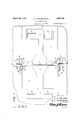
Figure 1, is atop planfview of agate in accordance with this invention.
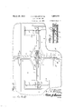
FigureQ is a similar view with the gates removed and the top plate'for the substantially cross-shaped housing also removed.
"r Figure 3 is a sectional view approximately on: the line 3-3 of Figure 1.
illustrate.,thc com )ensatin s rin s secured through the slot there is passed a pin' 6 that the rocker arm 8.
on the ends of the rocker arm thatis trally fixed to the throw .rod. I
Figure 10 is a sectional view through a portion of the casing and throw rodjto better illustrate the throw'lever andthe gate op.- 55 crating rods which are pivoted thereto." r
Figure 11 is a side elevation of afoot pedal operated j gate throwing mechanism, the ground casing being in section. it
Figure 12 is a sectional view approximatee0 ly on the line 1212 of Figure 11.
As previously stated our' improved gate may be used many place where a barrier'is desired, for instance, as a cattle guard, roald gate, farm gate, poultry gate, forest trail 55 gate, etc.
In Figures 1 to 5 of the 'drawingsweha-ve illustrated the improvement as a gate or barrier for highways andin this showing we embed in the roadway. a substantially crossshaped box or casing which may be construct ed of any 'desired'material, but which .ispre'ferably'forme'd of'either metal or concrete. The longitudinal branches 'ofythecasing. are arranged centrally in'theroadway 1, and the lateral branches are arranged transversely of the roadway. The. center of the casingf2, at
' the juncture 'of-itslongitudinal and lateral branches, is enlarged, as .disclosed byithe drawings and thesaid casing is' normally closed by a top plate 30f a shapecorrespond; ing to. that of thecasing. V
In the enlarged central portion ,of the casing. We arrange a longitudinally extending plate in the natureof a slide i. The slide is 85 suitably guided forrlongitudinal movementf and is. held from lateral :orxswingi ng mojvement. The slide, from: one of it sends,i'scentrally slotted or bifurcated, as at 5 "and lords a pivot forthe oppositely directed angularly disposed links? oftoggle levers. In addition to this the pine passes through a central opening in a rocker arm '8, "The second links}? ofthe toggle levers are 'pivotjed, as at l 0, to"the'sli-de 4, and the pivot 10 also connects thereto one end'of an arm or link 11 whose second end is pivoted toone endof Pivotally secured to i the "free end of 'the rocker arm 8 and extending through one of the longitudinal branches of the casing 2 there is a throw rod12. This rod has its outer end offset or arranged at an angle, as indicated by the numeral 13, and the said end 13''passes through an opening in an arm 14 that is fixed on and extends at an upward angle from the center of a crank shaft 15. The shaft has its central straight portion journaled in suitable bearings and its ends are ournaled in bearing openings in the ends of the outer lateral branch of the casing 2. Fixed to the angle end 13 of the throw rod 12 and to thei bottom of the casing there are oppositely directed coiled compensating springs 16, respectively. 7 f v v The shaft 15 has two cranked portions, and
the arms atth e ends of the said cranked por-s t i'onspas's through elongated slots or openings in thetop 3-for the casing, and each of the cranked'portions of the shaft is designed to be contacted by the wheels of the vehicle toftiirn the shaft and exert a longitudinal,
movementjto'tliethrow rod 12 to operate the gatesina mannerwhich will presently be, apparent The slides has its non-slotted or outer end connected to a second throw rod 17 the same having an angle or finger end 17', that is received through an arm 14: fixed on the centrallstraight portion of the crank shaft 18.
i The finger 17 has secured thereto the ends a of oppositely arranged angularly disposed .;the cranked ends offthe' shaft coilcompensating springs 16, the second ends of the springs being secured in the bottom of the casing 2. The shaft 18 has two cranked portions 18 whose angle sides or arms pass 1y disposed and angularly related links 7 and of the toggle levers there are 'securedrods i their outeriorfree ends bent upwardly, as
20 .that are :passed through the lateral branchesofthe casing and are suitablyguided therethrough to hold the same from swing ing orfla'ter'al movement. The rods 20 have at 21, and extended through elongated open ings in the cover plate 3. The angle ends 21 of .the rods have their. outer portions eX- f teildedl inwardly, as .at 23, and from thence fllaterally; as at 24;. The rods 20 are in the nature ofactuati'ng members for the gate and: the ofi'set or angle ends 2 1 thereof are in the'nature of kicker elements for the said gatefasiwill'be presently apparent; V The kicker elements 24 onthe ends 2 actuating rods are disposed inwardly with respect to the sides or edges ofthe roadway and tla cover. plate 3, atthe slotted ends thereof is provided with lateral extensions 25 that have secured thereon two-part bearings 26 for a shaft 25 that is formed with and extends laterally from the inner and lower corners of the gate frames 27, respectively It is to be noted that in this construction two gates are employed. The normally vertical and inner rails of the gate frames are for distinction indicated by the numeral-28 and the normally lower rails of the gateframe, are indicated for distinction by the numer'al29. The frames 27 are suitably covered by wires orthe like and therails 28 are disposed opposite but slightly out of alinement with the V fence posts 30. The offset end or kicker elef ments 21 on the actuating rods 20 are arranged between the rails 28 and 29 of the gate frames at the lower corners thereof so that the 'said kicker members-may contact with either the rail 28 or the rail 29 when the actuating rods 20 are imparted a longitudinal movement in amanner which will presently be described.
'Inorder to bracethe rails 28 and .29 and to likewise add weight to the pivoted corners thereof the ends of theshafts '25 are bent at opposite angles, as at 31and 32, and the ends 5 i of the said bent portions are Welded or other.- 7
wise connected to the oppositefaces of the rails 29 and 2810f the gate frames27., V
In orderto relieve the gates "from .undue shock when the same are swung to. openor closed position we arrange on the center of the cover plate'3 an abutment strip 33 and inner abutment strips 34 arranged a suitable distance inward of the sides of the roadway.
In operation we will suppose that the gates i are closed and a vehicle approaches the said gates in the direction'of the arrow in Figure 1 of the drawings. The wheels ofthe vehicle will engage with one pair of cranks on one of the crank shafts and thus swing the shaft in one direction. This will impart a longi% tudinal movement to'one of the throwrods 12 or 17, causingthesame to say, imparta longitudinal movement to the slide 4. Such Vided by the links 7 and 9 to expand or swing outwardly from the slide 4:, and such movement will also cause the link 11 to move longitudinally and swing the rocker arm 8 i movement will cause the toggle levers pro,-
to draw upon the second throw; rod 1am spread toggle levers will impart opposite longitudinal movements to the actuating rods i 'wing the second contact lever against the tens on of the compensating springs 16. The" 20, causing the keeper elements 23 to en'- 7 gage with the end rails 28 of the vgates 27 and swing the said gates on. their shafts or pivots 25 to partially raise the said gates and arrange the same beyond their center of gravity or automatically swing to open position. As the vehicle travels. 0n',;the axle thereof will engage with the second crank shaft, reversing the operation just described so'that the 'sec 1 so that the gates will from thence gravitate of the i 0nd throw.rod,say the rod 12, will swing the rocker arm to. a; second position to cause the toggle levers to swing toward each other and therebypmove the actuating rods'20 inwardly with respect to the casing 2. Such movement will cause the kicker elements 24 to contact with therails 29- of'the gates 27 to partly swing the said gates-and arrange the same beyondthe center 0f:their gravity and from thence swing to closed position .and into engagement with thezcompressible abutment member 33.
The brace-1ne1nbers-3l an'd132 add to the weight of the, pivoted eornersof the gates as well as reinforcing elements for the gate frames and these members 31 and 32, materially assist the gates in gravita ting to their opened and closed position and likewise tend to sustain the said gates in either of their said open or closed positions. In addition to this the brace members prevent the sagging or wobbling of the gate frames, and it will be apparent that the gates cannot be opened by direct pressure thereagainst and cannot be swung either open or closed by such movements. our construction no springs are employed except the compensating springs 16 for the contact levers 13, and that the parts constituting the improvement are strong and durable and are not liable to breakage or disarrangement. The cover plate 3, of course, is removed so that access to the parts arran ed in the casing may be had. The cross shaped casing is provided with spaced apertures 35 that afford drain outlets so that water will not accumulate in the easing.
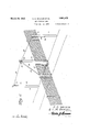
As disclosed by Figure 6 of the drawings the device may be operated by hand. In this instance a single gate frameis employed and the construction thereof is similar to that previously described. One of the end fence posts, idicated by the numeral 36, is of a greater length than the remaining fence posts and this elongated post 36 is arranged opposite the pivoted or shaft corner of the gate frame 37; The post 36 has secured thereon, adjacent to its top yi-eldably supported sheave wheels 38 that provide guides for cables 39, respectively, the ends of which are secured to the top bar or rail of the gate frame 37. The flexible elements are extended in opposite directions from the posts 36 and trained over grooved or sheave wheels 40 supported on posts 41 arranged on the opposite sides of the posts 36. The ends of the cables 39 have attached thereto handles 42 whereby a person approaching the gate from either direction may exert a pull upon one of the cables 39 to swing the gate to say open position, and after passing through the gate the handle on the end of the second cable is grasped to cause the gate to return to its closed position. ()f course, the pull on the cables is only sufficient to cause the gates 37 to swing beyond their It will also be apparent that with crank shafts 51 are, of course, located a suit-" able distance away from and attheopposite sides ofthe 53. The gates and the actuatlng'rods therefor are of a constructlon similar to that previously described so that l a detail description of these elements will not be attempted.
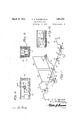
On the center of each of the shafts 5Lthere is secured a beveled gear 54- which isinmesh with a pinion 54'. Thepinions 5a. are fixed on the ends of the throwrod or shaft 55 and the said throw ro'd has secured thereon a pair of spaced laterally extending arms or levers 56. To the ends of each of the levers 56 and to thebottom of the casing 52 thereare secured the compensating springs 57. The rod has fixed thereon a rocker arm, 58 to whose ends theactuating rods 59 are loosely or piv-.
otally connected. Each shaft51 is provided with a pair of cranks and it will be obvious that a vehicle approaching the gates in either direction will have its wheels contactwith the cranks 5'0 and oneof theshafts 51 to cause';t;he; turning of the throw rodor shaft (which of course,is j ournaled in suitable bearings) to swing the rocker arm '58 to impart a lon itudinal movement to therods 59 and thereby swing the gates to either open or closed position in a manner heretofore described. f
InFigures 11 and '12 we have illustrated means whereby a single gate may be swung to either open or closed position by foot pedal means. The operating means is arranged in a suitable ground casing 60,-while the gate frame; 61 and the actuating rod 62 vonly slightly differ from the construction previous:
ly described. In this arrangement the upper offset orangle end 63' of the rod 62 hasits end formed with a lateral extension 6 f in the path of Contact with either. the normallyvertical or lower normally horizontalarm of they gate frame inaccordance with the push or the pull or ;,more strictly speaking the longitudinal moveinentof the actuating rod in two direc-. tions ,to' open. or close the gate. The gate is mounted in a manner as heretofore described and has its shaft. provided with" the'offset brace .forthe gate frame. In the casing there is journaled in suitable bearings a shaft 65, the said shaft having secured thereon a finger member 66 to which the inner end of the rod62- is pivoted. The shaft, outward of itsbearings 5'7, and at the opposite sides of the gate frame 61 has'fixed theretorocker arms 67, the ends of the saidrocker arms having secured thereto compensatlngsprings 'shaft and the stiles of the gate frame, an
actuating rod disposed for longitudinal re- 'ciprocatory'movement and having an offset andan-gle end that passes through the gate frame adjacent to the shaft and affords a foot;- pedals. v of the pedals the rocker arm or lever 67? will V 16 be swung to cause the turning of the shaft 65,
so that the finger 66 will exert a drawing or a pushing action against the rod 62, and consequently swing the gate to either its open 7' or closed positions in the same manner as heretofore described. One of the pedals on each side of the gate is employed for opening the gate and'gthe other for closing the gate as will be apparent.
' It is believed the foregoing description when read in connection with the accompanying drawings will fully set forth the construct-ion and advantages of the invention without further detailed description but obviously we do not wish to be restricted to the precise construction herein shown and described and, therefore, hold ourselves entitled .to make such changes therefrom as Y fairly fall within the scope of what we claim.
Having described the invention, we claim: 1. A gate frame having a laterally extending shaft at one of its lower corners, bearings weighted brace means between the ends of the shaft and the stiles of the gate frame, an
actuating rod disposed for longitudinal reciprocatory movement and having an offset and angle end, that passes through the gate pivot for the second toggle lever passing through the slot, a rocker arm centrally mounted on the pivot,'a link'connectionbetween said rocker arm and the pivot of the first link of the toggle lever, operating :rods pivotally secured respectively to the slide and rocker arm, a pivotally supported contact lever to which the ends of therods are connected and oppositely directed compensating springs for the contact levers.
tures.
CHARLES O. WALKER. LEVI M. BRAZIEL.
for the shaft, "rightangularly" arranged V I frame'adjacent to the shaft and affords a kicker member and designed when the rod is moved longitudinally to impart a kicking action against the rails of the gate rightangularly with respect to theshaft for swinging the gate beyond its center of gravity to permit of the said gate to gravitate to either open or closed position, and means for 1mparting a reciprocatory movement to the rod.
2; A gate framehaving a laterally extending shaft atone of its lower corners,bearings for the shaft, rightangularly arranged weighted brace means between the ends of the kicker member designed when the rod is moved longitudinallyto impart a kicking ac tion against the rails of the gate rightangularly with respect to the shaft for swinging the gate beyond its. center of gravity to permit said gate to gravitate to'either open or closed position, and means for imparting a reciprocatory movement to the rod, said means infcluding toggle levers to which the rod is pivoted, a slide to which one of the toggle levers is pivoted, said slidehavingga slot, .a
.In testimony whereof weaffix our signa-
Priority Applications (1)
| Application Number | Priority Date | Filing Date | Title |
|---|---|---|---|
| US501363A US1851472A (en) | 1930-12-10 | 1930-12-10 | All purpose gate |
Applications Claiming Priority (1)
| Application Number | Priority Date | Filing Date | Title |
|---|---|---|---|
| US501363A US1851472A (en) | 1930-12-10 | 1930-12-10 | All purpose gate |
Publications (1)
| Publication Number | Publication Date |
|---|---|
| US1851472A true US1851472A (en) | 1932-03-29 |
Family
ID=23993248
Family Applications (1)
| Application Number | Title | Priority Date | Filing Date |
|---|---|---|---|
| US501363A Expired - Lifetime US1851472A (en) | 1930-12-10 | 1930-12-10 | All purpose gate |
Country Status (1)
| Country | Link |
|---|---|
| US (1) | US1851472A (en) |
-
1930
- 1930-12-10 US US501363A patent/US1851472A/en not_active Expired - Lifetime
Similar Documents
| Publication | Publication Date | Title |
|---|---|---|
| US1851472A (en) | All purpose gate | |
| US2276500A (en) | Starting device | |
| US1963212A (en) | Gate operating mechanism | |
| US1963321A (en) | Garage door operating mechanism | |
| US1690924A (en) | Gate-operating means | |
| US338058A (en) | gillis | |
| US270565A (en) | aibbons | |
| US226522A (en) | kelso | |
| US726396A (en) | Farm-gate. | |
| US733684A (en) | Gate. | |
| US396046A (en) | mooee | |
| US411083A (en) | Farm-gate | |
| US1516723A (en) | Automatic door-operating device | |
| US1268815A (en) | Automatically-operated farm-gate. | |
| US1343023A (en) | Automatic gate | |
| US374742A (en) | Gus hookee ingeesoll | |
| US48698A (en) | Improved self-acting gate | |
| US66108A (en) | buechard | |
| US774052A (en) | Gate. | |
| US225686A (en) | Farm-gate | |
| US351337A (en) | plumley | |
| US305382A (en) | Signobs to themselves and james crosbie | |
| US92329A (en) | Improvement in gates | |
| US258517A (en) | Sliding gate | |
| US2301278A (en) | Vehicle operated gate |