US1851457A - Wrapping machine - Google Patents
Wrapping machine Download PDFInfo
- Publication number
- US1851457A US1851457A US339089A US33908929A US1851457A US 1851457 A US1851457 A US 1851457A US 339089 A US339089 A US 339089A US 33908929 A US33908929 A US 33908929A US 1851457 A US1851457 A US 1851457A
- Authority
- US
- United States
- Prior art keywords
- articles
- chamber
- wrapping
- article
- plunger
- Prior art date
- Legal status (The legal status is an assumption and is not a legal conclusion. Google has not performed a legal analysis and makes no representation as to the accuracy of the status listed.)
- Expired - Lifetime
Links
- 230000007246 mechanism Effects 0.000 description 27
- 239000010410 layer Substances 0.000 description 14
- 239000003292 glue Substances 0.000 description 3
- 239000011435 rock Substances 0.000 description 3
- 230000015572 biosynthetic process Effects 0.000 description 2
- 230000000694 effects Effects 0.000 description 2
- 238000002372 labelling Methods 0.000 description 2
- 230000003534 oscillatory effect Effects 0.000 description 2
- 238000010276 construction Methods 0.000 description 1
- 235000021186 dishes Nutrition 0.000 description 1
- 239000000835 fiber Substances 0.000 description 1
- 230000005484 gravity Effects 0.000 description 1
- 238000009499 grossing Methods 0.000 description 1
- 230000000977 initiatory effect Effects 0.000 description 1
- 238000004519 manufacturing process Methods 0.000 description 1
- 239000000463 material Substances 0.000 description 1
- NJPPVKZQTLUDBO-UHFFFAOYSA-N novaluron Chemical compound C1=C(Cl)C(OC(F)(F)C(OC(F)(F)F)F)=CC=C1NC(=O)NC(=O)C1=C(F)C=CC=C1F NJPPVKZQTLUDBO-UHFFFAOYSA-N 0.000 description 1
- 238000004806 packaging method and process Methods 0.000 description 1
- 230000000284 resting effect Effects 0.000 description 1
- 239000002356 single layer Substances 0.000 description 1
Images


Classifications
-
- B—PERFORMING OPERATIONS; TRANSPORTING
- B65—CONVEYING; PACKING; STORING; HANDLING THIN OR FILAMENTARY MATERIAL
- B65B—MACHINES, APPARATUS OR DEVICES FOR, OR METHODS OF, PACKAGING ARTICLES OR MATERIALS; UNPACKING
- B65B11/00—Wrapping, e.g. partially or wholly enclosing, articles or quantities of material, in strips, sheets or blanks, of flexible material
- B65B11/06—Wrapping articles, or quantities of material, by conveying wrapper and contents in common defined paths
- B65B11/18—Wrapping articles, or quantities of material, by conveying wrapper and contents in common defined paths in two or more straight paths
- B65B11/20—Wrapping articles, or quantities of material, by conveying wrapper and contents in common defined paths in two or more straight paths to fold the wrappers in tubular form about contents
- B65B11/22—Wrapping articles, or quantities of material, by conveying wrapper and contents in common defined paths in two or more straight paths to fold the wrappers in tubular form about contents and then to form closing folds of similar form at opposite ends of the tube
Definitions
- MASSACHUSETTS ASSIGNOBS TO IBAOKAGE MACHINERY COMPANY, OF SPRING- FIELD, MASSACHUSETTS, A CORPORATION OF MASSACHUSETTS WRAPPIN G MACHINE Application filed February 11, 1929. Serial 1W0. 339,089.
- This invention relates to wrapping machines. Its main object is the production of van improved machine which will arrange a plurality of articles in stack formation and wrap the assembly. A further object is to im rove and simplify the paper feed.
- furt er object is to provide a simple and effective control for the machine, functioning to permit the performance of the assembling operation only as articlesto be wrapped are supplied, but coordinated with the remaining mechanism to permit the ejection of an assembled stack from the stacking apparatus even though no additional articles are ready to be admitted.
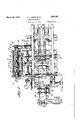
- Fig. 1 is a side elevation of amachine embodying our invention
- Fig. 2 is a top plan view thereof
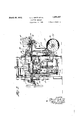
- Fig. 3 is a section on line 3-3 of Figs. 1 and 2;
- Fig. 4 is a section on line 4. 4 of Fig. 2;
- Fig. 5 is a detail in side elevation showing the position of the control mechanism when articles are being fed into the machine in the desired relation;
- Fig. 6 is a partial plan view of parts shown in Fig. 5;
- Figs. 7 and 8 are Views corresponding respectively to Figs. 5 and 6 but showing the position of the parts when no package is present;
- Fig. 10 is a perspective view illustrating the manner in which the articles are stacked and the operation of the smoothing devices for the paper;
- Fig. 11 is a section on line 11-11 of Fig. 2;
- Fig. 12 is a section on line 1212 of Fig. 2;
- Figs. 13 to 17 inclusive are diagrammatic views showing the assembly of a stack of articles and the start of the wrapping operation.
- the machine comprises an article feedway 5 A (Figs. 2 and 4) along which the incomby a sheet of wrapping paper supplied by 56 A a paper feeding mechanism C.
- the partially wrapped stack of articles is carried through a wrapping channel D having stationary side folders and labeling devices.
- -A control mechanism is provided for permitting operation of the stacking and wrapping mechanisms only when articles are in position to be fed into the assembling chamber. This control mechamsm is normally operated by the foremost article of the line entering the machine. After the stack has been formed, however, the control mechanism is artificially held in its operative position to permit the stack to be ejected into the wrapping channel.
- the articles are initially placed upon a shelf 20 (Fig. 4) supported from the main frame 21, and are carried along by belts 22.
- the forward ends of these belts pass around pulleys 23 secured to a shaft 24 which is driven by mechanism to be described.
- the rearward ends of the belts pass around pulleys 25 secured upon a pedestal 26.
- the belts are terminated short of the wrapping mechanism, for a purpose to be described, and a shelf 27 is positioned to serve as acontinuation of the surface of the belts, the articles sliding along the shelf under the pressure exerted on them by those articles which are still on the belts, and being heldin position by side guides 28.
- the shelf At its forward -erid, the shelf has a downturned portion 29 forming part of the entrance to the assembling cham.- ber B. Further steadying of the articles is accomplished by a short top plate 30 which terminates at the entrance to the assembling chamber, while adequate frictional pressure urging the line of articles along the feedway is assured by one or more rolls 31. Each of these rolls is mounted for free rotation in a bracket 32 (Fig. 1) andis urged downwardly 100 by springs 33 so as to keep the articles firmly pressed against the moving belts 22.
- the member 29 is a stationary plate 34 (Fig. 4), arisingfrom a web 35 attached to the frame, and serving as the back wall of the assembling chamber B.
- the chamber is mainly open on its front side, except for a plate 36 ocated opposite the member 29 and like it supported by the shelf 27. The incoming packages are pushed along the shelf 27 until they strike the late 36, being temporarily supported as t ey pass across the top of the assembling chamber by spring pressed tilting ledges 37.
- the articles are moved downwardly into the assembling chamber between an upper plunger 40 and a lower plunger 41.
- the upper plunger has a front Wall 42 and a back wall 43, and is supported rigidly upon a rod 44 running in guides 45 carried by the frame.
- the upper end of the rod is pivotally supported at 46 to a lever 47 secured upon a rock shaft 48.
- a counterweight 49 serving to balance the weight of the plunger.
- Pivoted to the counterweight at 50 (Fig. 1) is a short rod 51 adjustably secured to a. yoke 52, forked at 53 at its lower end to embrace a shaft 54 and bearing a cam roll 55 running in a groove 56 of a cam 57 secured upon the shaft 54.
- Shaft 54 bears a gear 58 meshing with a gear 59 of one fourth the number of teeth, loosely mounted upon the drive shaft 24 but controllably driven thereby as will be described.
- gear 59 When gear 59 is driven, the cam 57 causes the upper plunger to descend periodically to force the packages down into the assembling chamber.
- the lower plunger 41 is moved downwardly only by the pressure of the packages being moved by the upper plunger. It is supported on a rod 60 (Figs. 4 and 17) slidable in a bearing 61 depending from the web 35 and frictionally restrained from motion as will be described. Springs 62 are strained between a crosshead 63 attached to the lower end of the rod and a pin 64 upon the hearing, so that unless held by the frictional means referred to, the plunger would fly upwardly. To produce the desired frictional restraint, a fibre plug 65 is slidingly mounted in a recess formed in the bearing 61 so as to bear against the side of the rod.
- the plug is secured to the end of a bar 66 running in guides 67 and pressed towards the rod 60 by a spring 68.
- a lug 69 (Fig. 17) carried by the bar 66 is positioned to be struck periodically by mechanism to be described so as to draw the plug out of contact with the rod and thus to permit the lower plunger to fly up under the action of the springs 62.
- the upper position of the plunger is determined by a stop 70 positioned to strike the lower surface of the bearing 61.
- Paper feed v The paper in which the stacked articles are wrapped is supplied on a roll (Fig. 3)
- the shaft 81 which carries the upper feed rolls is journaled in brackets 97 (Figs. 2 and 3) pivoted to a shaft 98.
- the brackets extend beyond the shaft 81 to form a mounting for a bar 99 which acts both as a weight producing the necessary pressure between the feed rolls and as a handle ermitting the rolls to be separated when t e paper is to be threaded in.
- the bar is also utilized to support a series of paper guide fingers 100 extending between rolls 80 and assisting in inserting the paper and in maintaining the web flat as it passes between the feed rolls.
- a stationary cutting die 101 (Fig. 3) is secured to the frame beyond the paper feed rolls. Above this die a knife 102, bearing the usual spring pressed paper holders 103, is fitted for vertical reciprocation. This knife is operated by a pair. of arms 104 bearing adjustable set screws 105 which contact with the knife, the arms being fixed to the shaft 98 (previously referred to.
- An arm 106 also fixe to this shaft but extending in the opposite direction, carries a cam roll 107 (Fig. 2) resting on the surface of a cam 108 freely rotatable on the shaft 87. Adjacent this cam a hub 109 (Fig.
- ratchet 11 is fixed to the shaft, having a single ratchet tooth 110 coacting with a pawl 111 pivoted at 112 to the side 113.
- the arrangement of the ratchets an qaacam pawls is such that the feed rolls are operated when the shaft 87 rotates in one direction and the cutter is operated when the shaft rotates in the other direction.
- T ese chains carry grippers 117' of the type shown in our Patent 1,57 5,7 23, P
- the chambers formed by the grooves and the plates are joined by a pipe 122 with a 'suction pump 123.
- a valve 124 is positioned in the pipe, and is operated periodically through a rod .125 pivoted to a lever 126 rockingly mounted on the frame and hearing a roll 127 running in the groovev 128 of 129 carried by the shaft 54.
- the valve is opened by the means described after the delivery of the paper and remains openduring the stacking of the layers of articles in the assembling chamber.
- the effect of the suction (see Fig. 10) is to hold the paper smoothly across the opening of the assembling chamber and to exert a constant dragg action as the articles are progressively pushed down.
- Guides 130 overlie the plates 121 to direct the paper into proper position.
- the shaft 87 is given its necessary oscillatory motion by the following mechanism.
- a pinion gear 131 (Fig. 9) is fixed to the shaft and meshes with a rack 132 guided by rolls 133 carried by a guide 134 pivoted to the shaft.
- the lower end of the rack is pivoted to a crank 135 (best shown in Fig. 3) mounted on the end of a short shaft 136.
- This shaft carries a mutilated bevel gear 137 meshing with a mutilated gear 138 on the shaft 54 previously referred to.
- the dwell period of these gears occurs during the period when the articles are being assembled in and ejected from the chamber B, and during this period the paper feed rolls, the cutter, and the grippers are all atrest.
- the grippers start back and the cutter pawl 111 is picked up, causing a sheet to be severed, the paper feed ratchet 90 being meanwhile idle as the rotation of the bling chamber, it strikes shaft is in the wrong direction'for it.
- the cuther pawl becomes idle, the grippers start their advancewith the cut sheet, and the paper feed rolls deliver the leading end of the 'web as the cut sheet travels over theassembling chamber.
- Wrapping nwchanism As best shown in 13 and 16, the wraper sheet is shaped snugly around three sides of the stack of articles during its formation in the assembling chamber.
- the mechanism for completing the wrapping is generally similar to mechanisms previously employed, but will be described briefly as it differs in some details.
- a rear top folder 140 (Fig. 4) is fixed to a member 141 slidable upon rods 142 fixed to a carrier frame 143.
- This frame is fixed upon rods 144 slidably mounted in guides 145 secured to the machine frame and bearing upon their rear ends a pin 146 upon which a block 147 is pivotally mounted.
- the block runs in ways 148 formed upon the end of a rock lever 149 pivoted at 150 to the frame and bearing a cam roll 151 running in a cam groove cut in the face of the large gear 58.
- the carrier frame is formed to provide a spaced pushing element 152 adapted to contact with a partially wrappedstack of articles and carry it sideways out of the assembling chamber, and with side folders 153 which make a preliminary rear side tuck in the wrapper before the stack is ejected.
- An extension 154 is formed on the carrier to which is pivoted a gear segment 155 meshing with a rack 156 integral with the top folder 140.
- a spring-157 joins the top folder with the rods 144 so asto give a yielding connection.
- the wrapping channel comprises a bottom plate 158 and a top plate 159, and is flanked at its entrance by side end folders 160 which, as best shown in Fig. 3, lie just outside the side folders 153.
- Stationary top and bottom end folders 161 and 162 respectively are provided in conventional form to complete the wrapping operation.
- Control mchanimn ed from the shaft the supply of articles con-- tinues but the paper feed, the assembling plungers and the wrapping mechanism are stationary.
- a pawl 171 adapted to mesh with a single ratchet tooth 172 formed in a hub 173 fixed upon the drive shaft 24.
- a tail 174 is formed on the pawl in position to be engaged by one arm of a bell crank 175 pivoted at 176 to the machine frame. The other end of this bellcrank is connected by a rod 177 toa lever 178 pivoted ,at 179 to the rear of the assembling chamber B.
- abutment 180 is joined to this lever b a pin 181, and lies in the path of the pac agles advancing down the article feedwa W en no article is pressed against the a utment 180 by the crowding of the articles behind it, the bell crank 175 is positioned as shown in Fig. 7, either by the overbalancing effect of the horizontal arm of bell crank 175 or by a suitable spring, with its free end in the path of the tail 174 of the pawl 171.
- the end of the bell crank is tilted free of the tail of the pawl, allowingthe latter to drop by gravity into the ratchet tooth when the tooth comes by during the continuous rotation of the hub 173.
- the shape of the pawl and of the ratchet tooth, and the friction due to the pull exerted between them, are sulficient to prevent disengagement of the pawl from the ratchet until the bell crank 175 is againlowered.
- the interposition of the shelf 27 between the feed belts and'the control abutment 180 insures the presence of a series of articles,enough to complete a layer at least,before the push of the feed belts can be made effective u on the abutment to cause the performance 0? a stacking cycle.
- the upper plunger now rises to its initial position as shown in Fig. 14, permitting a second article to travel under it.
- This article is pushed down onto the first article by a stroke of the plunger of the same length as the first, lowering the first article and the lower plunger by the thickness of the second article (Fig. 15).
- the machine as shown, is designed to stack the articles in three layers, so that after the third descent of the plunger the stack is complete.
- the plunger then rises to an intermediate position, as shown in Fig. 16, in which it both keeps the abutment 180 pressed in to insure continued running of the machine, and holds back the flow of articles along the runway A.
- the carrier frame 143 now moves ahead, carrying the upper folder 140 and the side folders 153, which make prei 'the folding of'the wrapper is completed by the stationary folders 160, 161 and 162 in a conventional manner.
- the article ejected from the assembling chamber is left at the entrance to the wrapping channel until it is moved further along the ejection of the succeeding article. This successive movement of the articles continues until the leading article is grasped b the delivery belts.
- the articles a have been described as single flat articles for convenience. In practice, however, the articles may be of such a width that two, three or any other number are reuired to make up the width of the assembling hamber. The operation of the machine is not in any way changed by this, all the articles in a single layer acting like a single wider article.
- a wrapping machine comprising an assembling chamber wide enough to receive a plurality of articles side by side, an article supporting shelf extending to the chamber, means spaced from the chamber for feeding articles along the shelf, the articles in the space between the chamber and said means being forced solely by the pressure of other articles against them to a position across the opening tosaid chamber, whereby the presence of a series of abutting articles in said space is assured, means for delivering a sheet of paper across the opening to the chamber, a plunger operative to force a row of articles and said' paper into the chamber to partially wrap the paper around the articles, and control means actuated by the pressure of the foremost of a series of articles completely positioned across the opening of the chamber for initiating the movement of the plunger.
- a wrapping machine comprising an assembling chamber wide enough to receive a plurality of articles side by side, article feeding means supplying a series of abutting articles across the opening to said chamber, means for delivering a sheet of paper across the opening of the chamber, a plunger operative to force a row of articles and said paper into the chamber to partially wrap the paper around the articles, and controlmeans actuated by the pressure of the foremost of operable the serihs of articles when completel posit onedacross the opening of the chamber for m1t1atmg the movement of the plunger.
- a wrapping machine comprising a wrapping pocket, means for forcing an article to be wrapped into the pocket, and suction means adjacent to and facing away from the pocket for maintaining a pull on a sheet of wrapping paper placed across the opening to the pocket as the wrapper is drawn into the pocket by the entrance of the article.
- a wrapping machine comprising an assembling chamber, suction plates for holding a sheet of wrapping paper smoothly across the openlng to the chamber, and means for forcing into the pocket successive layers of articles, each layer having at least one article 4 therein. the paper being maintained smooth and tight-around the articles as the latter are successively stacked and partially wrapped in stack form in the chamber.
- a wrapping machine of the type in which the article and wrapper are preliminarily associated by sidewise entrance into a wrapping channel and the wrapping completed during movement of the article along the channel by a reciprocating pusher, a rear top folding plate slidably supported by the pusher, a rack secured to the folder, a gear segment pivoted to the pusher and meshing with the rack, a spring oining the segment, on the opposite side of its pivot from the gear teeth, with a fixed part of the machine, and an abutment at one side of the wrapping channel positioned to arrest the forward movement of the folder while permitting continued movement of the pusher.
- a wrapping machine comprising an assembling chamber, means for positioning a wrapper across the opening of said chamber, means for feeding a stream of articles adjacent the opening of said chamber.
- a plunger reciprocable a plurality of times during each machine cycle across the path of the articles to press a succession of one or more leading articles from said stream into the chamher.
- a supporting plunger forming one wall of the chamber and movable at each introduction of an article layer to increase step-bystep the size of the chamber, and mechanism to stop the operation of the machine in the absence of a complete file of articles extending across the opelpling to said chamber.
- a wrapping mac efcomprising an assemblingchamber, means for positioning a wrapper across the opening of said chamber, an article feed channel leading to the open-- ing of said chamber and having releasable enagement with an article adjacent the chamer opening, a conveyer belt terminatin short of the chamberopening and adapte to exert frictional pressure on the articles to push the leading articles of a continuous stream along the channel and across the chamber opening, a plunger reci rocable sociation with the wrapper, a positioning.
- abutment for arresting the movement of the leading article of the stream in position for engagement with the plunger, a detent projecting through the abutment to be actuated by the pressure exerted on the leading article by the article stream behind it, and mechamsm controlled by the detent for periodically arresting-the movement of the devices described other than the article conveyer unless the detent is actuated.
- a wrapping machine comprising an assembling chamber, means for deliveringa wrapping sheet across the opening of said chamber, means for delivering articles successively adjacent the top' of said chamber, a
- lunger reciprocable aplurality of times durmg a single cycle of the machines operation for forcing layers of one or more articles each into the assembling chamber for association with a single wrapping sheet, a supporting plunger spring pressed upwardly to form the bottom wall of the assembling chamber, a catch normally engageable with the plunger to restrain it from movement under the influence of the spring but operable to permit the plunger to move under the pressure of articles forced into the assembling chamber, 7
- an ejecting plunger operable to force a completed stack of articles out of the assembling chamber, and means movable at the operation of the ejecting plunger for releasing thecatch' and rmitting the spring to return the supporting plunger to its initial position.
- a wrapping machine comprising an assembling chamber having entrance and discharge apertures at right angles to each other, means for positioning a wrapper across the entrance to the chamber, means for delivering successive article layers into registration with the opening of the chamber, a plunger reciprocable through equal distances to press a series of said successive article layers into said chamber for association with a single wrapping sheet, and a pusher engageable with the completed assembly to carry it out of the chamber through the discharge aperture.
- a wrapping machine comprising an assembling chamber having entrance and dishe articles'to fee at least one leading article into the chamber for asmains? charge apertures at right anglesto each other, means for positioning a wrapper across, the entrance to the chamber, means for delivering successive article layers into registration wit the opening of the chamber, a plunger reciprocable through equal distances to press a series of said successive article layers into said chamber for association with a single I into groups having a predetermined number and arrangement of the articles, and means set into operation by the completion of each group to transfer said group to the wrapping mechanism, said wrapping mechanism including driving means controlled by the completion of each group.
- wrapping mechanism means for feeding articles, means cooperating with the feeding means to successively collect said articles into groups having a predetermined number and arrangement of the articles, and means set into operation by the completion of each group to transfer said group to the wrap ing mechanism
- said wrapping means include ing means for forwarding the group from the transfer device, stationary folders coacting with said means, and means for feeding wrapping material into the range of action ofthe transferdevice ahead of said folders.
- a wrapping machine in combination, means for feeding articles, means cooperating with the feeding means to successively'collect said articles into groups havin a predetermined number and arrangement 0% the articles, mechanism for wrapping said groups and self stopping driving means for said mechanism set into operation by completion of each group.
- a wrapping machine comprising an assembling chamber having entrance and discharge apertures at right angles to each other, means for positioning a wrapper across the entrance to the chamber, means for delivering successive article layers into registration with the opening of the chamber, a plunger reciprocable through equal distances to press a series of said successive article layers into said chamber for association with a single wrapping sheet, a supporting plunger forming one wall of the chamber and movable at each introduction of an article layer to increase step by step the size of the chamber, the
- wrapper being folded into U-form around the article assembly as the assembly is forced into the chamber, a folder movable across the completely positioned assembly for folding one side of the Wrapper against the article, a folding channel opening out of. the discharge aperture of the chamber, a pusher engageable with the completed assembly to carry it out of the chamber, a stationary folder past which the assembly is carried by the pusher to complete the folding of the wrapper in tubular form around the article, means in the folding channel for completing the folding of the wrapper, and means for returning the supporting plunger to its initial position upon the ejection of an assembly from the chamber.
Landscapes
- Engineering & Computer Science (AREA)
- Mechanical Engineering (AREA)
- Basic Packing Technique (AREA)
Description
March 29, 1932. E. L. M|TH ET AL WRAPPING nmcnmn Filed Feb. 11. 19 9 6 Sheets-Sheet 1' March 29, 1932. s rr 1,851,457
WRAPPING MACHINE Filed Feb. 11. 1929 s Sheets-Sheet 2 Q? INVENTOR. gzwx/wm 6 4 5 5 ATTORN S.
March 29, 1932. E. L. SMITH ET AL 1,851,457
WRAPPING MACHINE INVENTOR. 6% X/Nd M BY z? .9441
W 9 f/M A TTORNEYS.
March 29, 1932. E. L. SMITH ET7\L WRAPPING MACHINE Filed Feb. 1 .-1929 e Sheets-Sheet 4 March 29, 1932. E. L. SMITH ET AL WRAPPING MACHINE Filed Feb, 11, 1929 6 Sheets-Sheet 5 INVENTOR.
ATTORNEYS.
Maich 29, 1932.
EL 1.. SMITH ET AL WRAPPING MACHINE Filed Feb. ll, 1929 6 Sheets-Sheet 6 'INVENTOR.
17/141/ 1 v ATTORNEYS.
Patented Mar. 29, 1932 UNITED sTATEs PATENT OFFICE ELMER L. SMITH, OF LONGMEADOW, AND FBEDERIC B. FULLER, OF SPRINGFIELD,
MASSACHUSETTS, ASSIGNOBS TO IBAOKAGE MACHINERY COMPANY, OF SPRING- FIELD, MASSACHUSETTS, A CORPORATION OF MASSACHUSETTS WRAPPIN G MACHINE Application filed February 11, 1929. Serial 1W0. 339,089.
This invention relates to wrapping machines. Its main object is the production of van improved machine which will arrange a plurality of articles in stack formation and wrap the assembly. A further object is to im rove and simplify the paper feed.
furt er object is to provide a simple and effective control for the machine, functioning to permit the performance of the assembling operation only as articlesto be wrapped are supplied, but coordinated with the remaining mechanism to permit the ejection of an assembled stack from the stacking apparatus even though no additional articles are ready to be admitted. Other objects will appear from the following description and claims;
Referring to the drawings: Fig. 1 is a side elevation of amachine embodying our invention; Fig. 2 is a top plan view thereof;
Fig. 3 is a section on line 3-3 of Figs. 1 and 2;
Fig. 4 is a section on line 4. 4 of Fig. 2; Fig. 5 is a detail in side elevation showing the position of the control mechanism when articles are being fed into the machine in the desired relation;
Fig. 6 is a partial plan view of parts shown in Fig. 5;
Figs. 7 and 8 are Views corresponding respectively to Figs. 5 and 6 but showing the position of the parts when no package is present;
9 is a detail of the driving mechanism for the paper feed;
Fig. 10 is a perspective view illustrating the manner in which the articles are stacked and the operation of the smoothing devices for the paper;
Fig. 11 is a section on line 11-11 of Fig. 2;
Fig. 12 is a section on line 1212 of Fig. 2; and
Figs. 13 to 17 inclusive are diagrammatic views showing the assembly of a stack of articles and the start of the wrapping operation.
General summon The machine comprises an article feedway 5 A (Figs. 2 and 4) along which the incomby a sheet of wrapping paper supplied by 56 A a paper feeding mechanism C. From the assembling chamber, the partially wrapped stack of articles is carried through a wrapping channel D having stationary side folders and labeling devices. -A control mechanism is provided for permitting operation of the stacking and wrapping mechanisms only when articles are in position to be fed into the assembling chamber. This control mechamsm is normally operated by the foremost article of the line entering the machine. After the stack has been formed, however, the control mechanism is artificially held in its operative position to permit the stack to be ejected into the wrapping channel.
Article feed'way The articles are initially placed upon a shelf 20 (Fig. 4) supported from the main frame 21, and are carried along by belts 22. The forward ends of these beltspass around pulleys 23 secured to a shaft 24 which is driven by mechanism to be described. The rearward ends of the belts pass around pulleys 25 secured upon a pedestal 26. The belts are terminated short of the wrapping mechanism, for a purpose to be described, and a shelf 27 is positioned to serve as acontinuation of the surface of the belts, the articles sliding along the shelf under the pressure exerted on them by those articles which are still on the belts, and being heldin position by side guides 28. At its forward -erid, the shelf has a downturned portion 29 forming part of the entrance to the assembling cham.- ber B. Further steadying of the articles is accomplished by a short top plate 30 which terminates at the entrance to the assembling chamber, while adequate frictional pressure urging the line of articles along the feedway is assured by one or more rolls 31. Each of these rolls is mounted for free rotation in a bracket 32 (Fig. 1) andis urged downwardly 100 by springs 33 so as to keep the articles firmly pressed against the moving belts 22.
Assembling chamber JBelow the member 29 is a stationary plate 34 (Fig. 4), arisingfrom a web 35 attached to the frame, and serving as the back wall of the assembling chamber B. The chamber is mainly open on its front side, except for a plate 36 ocated opposite the member 29 and like it supported by the shelf 27. The incoming packages are pushed along the shelf 27 until they strike the late 36, being temporarily supported as t ey pass across the top of the assembling chamber by spring pressed tilting ledges 37.
The articles are moved downwardly into the assembling chamber between an upper plunger 40 and a lower plunger 41. The upper plunger has a front Wall 42 and a back wall 43, and is supported rigidly upon a rod 44 running in guides 45 carried by the frame. The upper end of the rod is pivotally supported at 46 to a lever 47 secured upon a rock shaft 48. Also secured to this rock shaft is a counterweight 49 serving to balance the weight of the plunger. Pivoted to the counterweight at 50 (Fig. 1) is a short rod 51 adjustably secured to a. yoke 52, forked at 53 at its lower end to embrace a shaft 54 and bearing a cam roll 55 running in a groove 56 of a cam 57 secured upon the shaft 54. Shaft 54 bears a gear 58 meshing with a gear 59 of one fourth the number of teeth, loosely mounted upon the drive shaft 24 but controllably driven thereby as will be described. When gear 59 is driven, the cam 57 causes the upper plunger to descend periodically to force the packages down into the assembling chamber.
The lower plunger 41 is moved downwardly only by the pressure of the packages being moved by the upper plunger. It is supported on a rod 60 (Figs. 4 and 17) slidable in a bearing 61 depending from the web 35 and frictionally restrained from motion as will be described. Springs 62 are strained between a crosshead 63 attached to the lower end of the rod and a pin 64 upon the hearing, so that unless held by the frictional means referred to, the plunger would fly upwardly. To produce the desired frictional restraint, a fibre plug 65 is slidingly mounted in a recess formed in the bearing 61 so as to bear against the side of the rod. The plug is secured to the end of a bar 66 running in guides 67 and pressed towards the rod 60 by a spring 68. A lug 69 (Fig. 17) carried by the bar 66 is positioned to be struck periodically by mechanism to be described so as to draw the plug out of contact with the rod and thus to permit the lower plunger to fly up under the action of the springs 62. The upper position of the plungeris determined by a stop 70 positioned to strike the lower surface of the bearing 61. Paper feed v The paper in which the stacked articles are wrapped is supplied on a roll (Fig. 3)
mounted on an arbor 76' supported upon a bracket 7 7 supported on the main frame.
The web 'w is led off this roll over a driven rotatable upon a shaft 87 A hub 88 (F ig.
12) isfixed to this shaftadj acent the sprocket and is formed with a single ratchet tooth'89. A pawl 90, pivoted at 91 to the side of the sprocket and urged radially inwardly by a spring 92, forms the driving connection between shaft 87 and the sprocket 86,0perating toturn the sprocket when the shaft rotates in one direction but to leave the sprocket idle when the shaft rotates the .otherway- The chain 85, by which motion is communicated from shaft 87 to the paper feeding rolls, also passes around a sprocket 93 (Fig. 1) mounted on a shaft 94 carrying a glue roll 95. This roll receives glue from a glue pot 96 and applies it near one edge of the wrapper as it is fed from the feed rolls to the wrapping mechanism. I
The shaft 81 which carries the upper feed rolls is journaled in brackets 97 (Figs. 2 and 3) pivoted to a shaft 98. The brackets extend beyond the shaft 81 to form a mounting for a bar 99 which acts both as a weight producing the necessary pressure between the feed rolls and as a handle ermitting the rolls to be separated when t e paper is to be threaded in. The bar is also utilized to support a series of paper guide fingers 100 extending between rolls 80 and assisting in inserting the paper and in maintaining the web flat as it passes between the feed rolls.
A stationary cutting die 101 (Fig. 3) is secured to the frame beyond the paper feed rolls. Above this die a knife 102, bearing the usual spring pressed paper holders 103, is fitted for vertical reciprocation. This knife is operated by a pair. of arms 104 bearing adjustable set screws 105 which contact with the knife, the arms being fixed to the shaft 98 (previously referred to. An arm 106, also fixe to this shaft but extending in the opposite direction, carries a cam roll 107 (Fig. 2) resting on the surface of a cam 108 freely rotatable on the shaft 87. Adjacent this cam a hub 109 (Fig. 11) is fixed to the shaft, having a single ratchet tooth 110 coacting with a pawl 111 pivoted at 112 to the side 113. The arrangement of the ratchets an qaacam pawls is such that the feed rolls are operated when the shaft 87 rotates in one direction and the cutter is operated when the shaft rotates in the other direction.
Likewise mounted on the shaft 87 are sprockets 115 connected by chains 116 with sprockets 117 idl mounted on the frame of the machine. T ese chains carry grippers 117' of the type shown in our Patent 1,57 5,7 23, P
March 9, 1926, adapted to carry the cut sheet of paper to a position directly under the plunger 40. The grippers have not been illustrated in detail in the present case, as their construction will be clear from the patent referred to. The chains are moved by the oscillatory motion of shaft 87 to carry the grippers back and forth in a straight line. The
-ppers run in suitable guides 118 (Fig. 4), parallel to which are channeled paper guides 119.
The 'ppers deposit the cut and glued sheet of pdaper directly over the assem ling chamber B. Underlying the paper when in this position are grooved bars 120 (Figs. 4
and 10) covered by perforated plates 121."
The chambers formed by the grooves and the plates are joined by a pipe 122 with a 'suction pump 123. A valve 124 is positioned in the pipe, and is operated periodically through a rod .125 pivoted to a lever 126 rockingly mounted on the frame and hearing a roll 127 running in the groovev 128 of 129 carried by the shaft 54. The valve is opened by the means described after the delivery of the paper and remains openduring the stacking of the layers of articles in the assembling chamber. The effect of the suction (see Fig. 10) is to hold the paper smoothly across the opening of the assembling chamber and to exert a constant dragg action as the articles are progressively pushed down. Guides 130 overlie the plates 121 to direct the paper into proper position.
The shaft 87 is given its necessary oscillatory motion by the following mechanism. A pinion gear 131 (Fig. 9) is fixed to the shaft and meshes with a rack 132 guided by rolls 133 carried by a guide 134 pivoted to the shaft. The lower end of the rack is pivoted to a crank 135 (best shown in Fig. 3) mounted on the end of a short shaft 136. This shaft carries a mutilated bevel gear 137 meshing with a mutilated gear 138 on the shaft 54 previously referred to. The dwell period of these gears occurs during the period when the articles are being assembled in and ejected from the chamber B, and during this period the paper feed rolls, the cutter, and the grippers are all atrest. After this period is completed, the grippers start back and the cutter pawl 111 is picked up, causing a sheet to be severed, the paper feed ratchet 90 being meanwhile idle as the rotation of the bling chamber, it strikes shaft is in the wrong direction'for it. When the rotation of the shaft reverses, the cuther pawl becomes idle, the grippers start their advancewith the cut sheet, and the paper feed rolls deliver the leading end of the 'web as the cut sheet travels over theassembling chamber. Wrapping nwchanism As best shown in 13 and 16, the wraper sheet is shaped snugly around three sides of the stack of articles during its formation in the assembling chamber. The mechanism for completing the wrapping is generally similar to mechanisms previously employed, but will be described briefly as it differs in some details. A rear top folder 140 (Fig. 4) is fixed to a member 141 slidable upon rods 142 fixed to a carrier frame 143. This frame is fixed upon rods 144 slidably mounted in guides 145 secured to the machine frame and bearing upon their rear ends a pin 146 upon which a block 147 is pivotally mounted. The block runs in ways 148 formed upon the end of a rock lever 149 pivoted at 150 to the frame and bearing a cam roll 151 running in a cam groove cut in the face of the large gear 58. By this mechanism the carrier frame is reciprocated back and forth once whenever a stack of articles is completely assembled in the chamber B.
The carrier frame is formed to provide a spaced pushing element 152 adapted to contact with a partially wrappedstack of articles and carry it sideways out of the assembling chamber, and with side folders 153 which make a preliminary rear side tuck in the wrapper before the stack is ejected. An extension 154 is formed on the carrier to which is pivoted a gear segment 155 meshing with a rack 156 integral with the top folder 140. A spring-157 joins the top folder with the rods 144 so asto give a yielding connection. When the carrier frame is advanced the top folder 140 initially travels with it, preceding the side folders and the pusher as will be seen from Figs. 15 and 16. When the top folder has traveled across the assemthe further bar 120 and stops, the spring-157 stretching during further motion of the frame. The side folders 153 also contact with the wrapper before the pushers hit the article, which moves completely across the assembling chamber to carry the partially wrapped stack into the wrapping channel D. 4
The wrapping channel comprises a bottom plate 158 and a top plate 159, and is flanked at its entrance by side end folders 160 which, as best shown in Fig. 3, lie just outside the side folders 153. Stationary top and bottom end folders 161 and 162 respectively are provided in conventional form to complete the wrapping operation. A labeling apparatus 163, operated by a suction pump 164 in any desired manner, applies printed end labels to the wrapped stacks, which then pass between del very belts 165.
Control mchanimn ed from the shaft the supply of articles con-- tinues but the paper feed, the assembling plungers and the wrapping mechanism are stationary.
Pivoted at 170 (Fig. 5) to one side of the gear 59 is a pawl 171 adapted to mesh with a single ratchet tooth 172 formed in a hub 173 fixed upon the drive shaft 24. A tail 174 is formed on the pawl in position to be engaged by one arm of a bell crank 175 pivoted at 176 to the machine frame. The other end of this bellcrank is connected by a rod 177 toa lever 178 pivoted ,at 179 to the rear of the assembling chamber B. An abutment 180 is joined to this lever b a pin 181, and lies in the path of the pac agles advancing down the article feedwa W en no article is pressed against the a utment 180 by the crowding of the articles behind it, the bell crank 175 is positioned as shown in Fig. 7, either by the overbalancing effect of the horizontal arm of bell crank 175 or by a suitable spring, with its free end in the path of the tail 174 of the pawl 171. As soon asan article is pressed firmly against the abutment 180, the end of the bell crank is tilted free of the tail of the pawl, allowingthe latter to drop by gravity into the ratchet tooth when the tooth comes by during the continuous rotation of the hub 173. The shape of the pawl and of the ratchet tooth, and the friction due to the pull exerted between them, are sulficient to prevent disengagement of the pawl from the ratchet until the bell crank 175 is againlowered.
While it is desirable to prevent operation of the paper feed and the stacking mechanism when the articles are not properly presented for assembl it is desirable'to eject a completely assem led stack into the wrappin mechanism and to return the mechanism to t e condition where it is ready to start the assembling of another stack whether or not the articles are present in the feedway. For this ejection, it makes no difference whether additional articles are ready to be assembled, and to delaythereturn of the mechanism to the normal starting position because of such absence of articles would unduly delay the operation of the machine. The solution which we have made of this apparent difficulty rests in the design of the cam o erating the upper assembling plunger and in the form of that plunger itsel The action will i be clearest from a comparison of Figs. 14 and 16, the former showing the normal return of the plunger after an assembling stroke and the latter the return of the plunger after the last article of a stack has been lowered into the assembling chamber. It will be noticed that in the case of Fig. 16 the plunger only rises to a fraction of its normal elevation, and that its front wall contacts with the abutment 180. The plunger thus takes the place of an article during the ejection of the assembled stack from the chamber B, and is raised to its normal position releasing the abutment only after the assembling motion has been completed. The interposition of the shelf 27 between the feed belts and'the control abutment 180 insures the presence of a series of articles,enough to complete a layer at least,before the push of the feed belts can be made effective u on the abutment to cause the performance 0? a stacking cycle.
Operation of the machine The general operation of the machine will now be described with particular reference to Figs. 13 to 17. In this description, it will be assumed that a continuous flow of articles is traveling down the feedway, so that no in terruption of the operation of the machine will result. It will also be assumed, in choosing a starting point, that a cut strip of the paper w has been carried by the grippers into a position across the top of the assembling chamber as shown in Fig. 17 The first motion of the machine is the descent of the upper plunger 40, as shown in Fig. 13, forcing the leading article downwardly first against the wrapping paper and then against the lower plunger, the latter being carried downwardly from the position of Fig. 17 to that of Fig. 14. The paper is held'smoothly by. the suction exerted through the perforated plates 121 during this movement.
The upper plunger now rises to its initial position as shown in Fig. 14, permitting a second article to travel under it. This article is pushed down onto the first article by a stroke of the plunger of the same length as the first, lowering the first article and the lower plunger by the thickness of the second article (Fig. 15). The machine, as shown, is designed to stack the articles in three layers, so that after the third descent of the plunger the stack is complete. The plunger then rises to an intermediate position, as shown in Fig. 16, in which it both keeps the abutment 180 pressed in to insure continued running of the machine, and holds back the flow of articles along the runway A. The carrier frame 143 now moves ahead, carrying the upper folder 140 and the side folders 153, which make prei 'the folding of'the wrapper is completed by the stationary folders 160, 161 and 162 in a conventional manner. The article ejected from the assembling chamber is left at the entrance to the wrapping channel until it is moved further along the ejection of the succeeding article. This successive movement of the articles continues until the leading article is grasped b the delivery belts. As an article is ejecte the lug 69 on the rod holding the friction plug 65 is contacted b y a lug 185 on the rods 144, drawing the p ug away from the rod 60 and permitting the lower lunger to rise under the influence of the springs 62 until it is stopped by the contact of the stop 70 with the under side of the bearing 61. The lower plunger being narrower than the space between the pushers 152, it does not in its elevated position interfere with the rearward motion of these members.
The articles a have been described as single flat articles for convenience. In practice, however, the articles may be of such a width that two, three or any other number are reuired to make up the width of the assembling hamber. The operation of the machine is not in any way changed by this, all the articles in a single layer acting like a single wider article.
Claims:
1. A wrapping machine comprising an assembling chamber wide enough to receive a plurality of articles side by side, an article supporting shelf extending to the chamber, means spaced from the chamber for feeding articles along the shelf, the articles in the space between the chamber and said means being forced solely by the pressure of other articles against them to a position across the opening tosaid chamber, whereby the presence of a series of abutting articles in said space is assured, means for delivering a sheet of paper across the opening to the chamber, a plunger operative to force a row of articles and said' paper into the chamber to partially wrap the paper around the articles, and control means actuated by the pressure of the foremost of a series of articles completely positioned across the opening of the chamber for initiating the movement of the plunger.
2. A. wrapping machine comprising an assembling chamber wide enough to receive a plurality of articles side by side, article feeding means supplying a series of abutting articles across the opening to said chamber, means for delivering a sheet of paper across the opening of the chamber, a plunger operative to force a row of articles and said paper into the chamber to partially wrap the paper around the articles, and controlmeans actuated by the pressure of the foremost of operable the serihs of articles when completel posit onedacross the opening of the chamber for m1t1atmg the movement of the plunger.
'3. A wrapping machine comprising a wrapping pocket, means for forcing an article to be wrapped into the pocket, and suction means adjacent to and facing away from the pocket for maintaining a pull on a sheet of wrapping paper placed across the opening to the pocket as the wrapper is drawn into the pocket by the entrance of the article.
4. A wrapping machine comprising an assembling chamber, suction plates for holding a sheet of wrapping paper smoothly across the openlng to the chamber, and means for forcing into the pocket successive layers of articles, each layer having at least one article 4 therein. the paper being maintained smooth and tight-around the articles as the latter are successively stacked and partially wrapped in stack form in the chamber.
5. In a wrapping machine of the type in which the article and wrapper are preliminarily associated by sidewise entrance into a wrapping channel and the wrapping completed during movement of the article along the channel by a reciprocating pusher, a rear top folding plate slidably supported by the pusher, a rack secured to the folder, a gear segment pivoted to the pusher and meshing with the rack, a spring oining the segment, on the opposite side of its pivot from the gear teeth, with a fixed part of the machine, and an abutment at one side of the wrapping channel positioned to arrest the forward movement of the folder while permitting continued movement of the pusher.
6. In a wrapping machine of the type in which the article andwrapper are preliminarily associated bysidewise entrance into a wrapping channel and the wrapping completed during movement of the article along the channel by a reciprocating pusher, a rear top folding plate slidably carried .by the pusher, a spring connection between the pusher and the folding plate, and an abutment at one side of the wrapping channel positioned to arrest the forward movement of the folder while permitting continued movement of the pusher.
7. A wrapping machine comprising an assembling chamber, means for positioning a wrapper across the opening of said chamber, means for feeding a stream of articles adjacent the opening of said chamber. a plunger reciprocable a plurality of times during each machine cycle across the path of the articles to press a succession of one or more leading articles from said stream into the chamher. a supporting plunger forming one wall of the chamber and movable at each introduction of an article layer to increase step-bystep the size of the chamber, and mechanism to stop the operation of the machine in the absence of a complete file of articles extending across the opelpling to said chamber.
8. A wrapping mac efcomprising an assemblingchamber, means for positioning a wrapper across the opening of said chamber, an article feed channel leading to the open-- ing of said chamber and having releasable enagement with an article adjacent the chamer opening, a conveyer belt terminatin short of the chamberopening and adapte to exert frictional pressure on the articles to push the leading articles of a continuous stream along the channel and across the chamber opening, a plunger reci rocable sociation with the wrapper, a positioning.
abutment for arresting the movement of the leading article of the stream in position for engagement with the plunger, a detent projecting through the abutment to be actuated by the pressure exerted on the leading article by the article stream behind it, and mechamsm controlled by the detent for periodically arresting-the movement of the devices described other than the article conveyer unless the detent is actuated. i
9. A wrapping machine comprising an assembling chamber, means for deliveringa wrapping sheet across the opening of said chamber, means for delivering articles successively adjacent the top' of said chamber, a
lunger reciprocable aplurality of times durmg a single cycle of the machines operation for forcing layers of one or more articles each into the assembling chamber for association with a single wrapping sheet, a supporting plunger spring pressed upwardly to form the bottom wall of the assembling chamber, a catch normally engageable with the plunger to restrain it from movement under the influence of the spring but operable to permit the plunger to move under the pressure of articles forced into the assembling chamber, 7
an ejecting plunger operable to force a completed stack of articles out of the assembling chamber, and means movable at the operation of the ejecting plunger for releasing thecatch' and rmitting the spring to return the supporting plunger to its initial position.
10. A wrapping machine comprising an assembling chamber having entrance and discharge apertures at right angles to each other, means for positioning a wrapper across the entrance to the chamber, means for delivering successive article layers into registration with the opening of the chamber, a plunger reciprocable through equal distances to press a series of said successive article layers into said chamber for association with a single wrapping sheet, and a pusher engageable with the completed assembly to carry it out of the chamber through the discharge aperture.
11. A wrapping machine comprising an assembling chamber having entrance and dishe articles'to fee at least one leading article into the chamber for asmains? charge apertures at right anglesto each other, means for positioning a wrapper across, the entrance to the chamber, means for delivering successive article layers into registration wit the opening of the chamber, a plunger reciprocable through equal distances to press a series of said successive article layers into said chamber for association with a single I into groups having a predetermined number and arrangement of the articles, and means set into operation by the completion of each group to transfer said group to the wrapping mechanism, said wrapping mechanism including driving means controlled by the completion of each group.
13. In a packaging machine in combination, wrapping mechanism, means for feeding articles, means cooperating with the feeding means to successively collect said articles into groups having a predetermined number and arrangement of the articles, and means set into operation by the completion of each group to transfer said group to the wrap ing mechanism, said wrapping means inclu ing means for forwarding the group from the transfer device, stationary folders coacting with said means, and means for feeding wrapping material into the range of action ofthe transferdevice ahead of said folders.
14. In a wrapping machine in combination, means for feeding articles, means cooperating with the feeding means to successively'collect said articles into groups havin a predetermined number and arrangement 0% the articles, mechanism for wrapping said groups and self stopping driving means for said mechanism set into operation by completion of each group.
15. A wrapping machine comprising an assembling chamber having entrance and discharge apertures at right angles to each other, means for positioning a wrapper across the entrance to the chamber, means for delivering successive article layers into registration with the opening of the chamber, a plunger reciprocable through equal distances to press a series of said successive article layers into said chamber for association with a single wrapping sheet, a supporting plunger forming one wall of the chamber and movable at each introduction of an article layer to increase step by step the size of the chamber, the
wrapper being folded into U-form around the article assembly as the assembly is forced into the chamber, a folder movable across the completely positioned assembly for folding one side of the Wrapper against the article, a folding channel opening out of. the discharge aperture of the chamber, a pusher engageable with the completed assembly to carry it out of the chamber, a stationary folder past which the assembly is carried by the pusher to complete the folding of the wrapper in tubular form around the article, means in the folding channel for completing the folding of the wrapper, and means for returning the supporting plunger to its initial position upon the ejection of an assembly from the chamber.
In testimony whereof we have aflixed our signatures.
ELMER L. SMITH. FREDERIC B. FULLER.
Priority Applications (2)
| Application Number | Priority Date | Filing Date | Title |
|---|---|---|---|
| US339089A US1851457A (en) | 1929-02-11 | 1929-02-11 | Wrapping machine |
| DE1930605492D DE605492C (en) | 1929-02-11 | 1930-02-12 | Wrapping machine for wrapping several items in a common cover |
Applications Claiming Priority (1)
| Application Number | Priority Date | Filing Date | Title |
|---|---|---|---|
| US339089A US1851457A (en) | 1929-02-11 | 1929-02-11 | Wrapping machine |
Publications (1)
| Publication Number | Publication Date |
|---|---|
| US1851457A true US1851457A (en) | 1932-03-29 |
Family
ID=23327451
Family Applications (1)
| Application Number | Title | Priority Date | Filing Date |
|---|---|---|---|
| US339089A Expired - Lifetime US1851457A (en) | 1929-02-11 | 1929-02-11 | Wrapping machine |
Country Status (2)
| Country | Link |
|---|---|
| US (1) | US1851457A (en) |
| DE (1) | DE605492C (en) |
Cited By (13)
| Publication number | Priority date | Publication date | Assignee | Title |
|---|---|---|---|---|
| US2592793A (en) * | 1945-05-14 | 1952-04-15 | Lynch Package Machinery Corp | Wrapping machine for butter and the like |
| US2637961A (en) * | 1949-11-01 | 1953-05-12 | James M Sutton | Package wrapping apparatus |
| US2675657A (en) * | 1954-04-20 | Packaging machine control | ||
| US2685157A (en) * | 1949-07-09 | 1954-08-03 | Lynch Corp | Machine for wrapping articles and control therefor |
| US2704918A (en) * | 1953-09-14 | 1955-03-29 | Varick Ind Inc | Packaging apparatus |
| US2765599A (en) * | 1952-04-17 | 1956-10-09 | Continental Can Co | Can arranging and wrapping method and apparatus |
| US2846834A (en) * | 1953-06-09 | 1958-08-12 | British Sugar Corp Ltd | Package wrapping machines |
| US2879637A (en) * | 1956-10-17 | 1959-03-31 | Schroeder Machines Corp | Package handling apparatus |
| US3075325A (en) * | 1959-12-08 | 1963-01-29 | Hauni Werke Koerber & Co Kg | Method and apparatus for feeding wrapping material into a wrapping machine |
| US3354600A (en) * | 1964-10-09 | 1967-11-28 | Int Paper Co | Bundling machine |
| US3803797A (en) * | 1971-03-04 | 1974-04-16 | G Zax | Method of packing stacks of flat articles into packages and framework used for effecting same |
| US5379574A (en) * | 1992-04-24 | 1995-01-10 | Benz & Hilgers Gmbh | Apparatus for packaging individual objects, especially packages, e.g. of prepacked foodstuffs |
| US5501065A (en) * | 1992-04-24 | 1996-03-26 | Benz & Hilgers Gmbh | Apparatus for packaging individual objects, especially foodstuff packages |
Families Citing this family (7)
| Publication number | Priority date | Publication date | Assignee | Title |
|---|---|---|---|---|
| DE1045309B (en) * | 1956-02-15 | 1958-11-27 | Alofin Verwaltungs & Finanzier | Device for packing blocks of kneadable masses |
| DE1169361B (en) * | 1959-12-08 | 1964-04-30 | Hauni Werke Koerber & Co Kg | Method and device for feeding wrapping material to a packaging web |
| DE1154754B (en) * | 1960-08-04 | 1963-09-19 | Robert Czerweny Von Arland | Device for wrapping several boxes, e.g. B. ignition wood boxes, to a larger package |
| DE1247931B (en) * | 1963-08-22 | 1967-08-17 | Noack E Th Verpackungsmasch | Packaging machine for the individual sealing of capsules u. like |
| DE1228554B (en) * | 1964-06-19 | 1966-11-10 | Focke Pfuhl Verpack Automat | Device for wrapping packages on all sides |
| SE323324B (en) * | 1967-02-20 | 1970-04-27 | Sunds Ab | |
| IT1069186B (en) * | 1976-11-15 | 1985-03-25 | Wrapmatic Spa | AUTOMATIC MACHINE FOR THE PACKAGING OF PARALLEL-PIPED PRODUCTS, PARTICULARLY PAPER SAVING |
-
1929
- 1929-02-11 US US339089A patent/US1851457A/en not_active Expired - Lifetime
-
1930
- 1930-02-12 DE DE1930605492D patent/DE605492C/en not_active Expired
Cited By (13)
| Publication number | Priority date | Publication date | Assignee | Title |
|---|---|---|---|---|
| US2675657A (en) * | 1954-04-20 | Packaging machine control | ||
| US2592793A (en) * | 1945-05-14 | 1952-04-15 | Lynch Package Machinery Corp | Wrapping machine for butter and the like |
| US2685157A (en) * | 1949-07-09 | 1954-08-03 | Lynch Corp | Machine for wrapping articles and control therefor |
| US2637961A (en) * | 1949-11-01 | 1953-05-12 | James M Sutton | Package wrapping apparatus |
| US2765599A (en) * | 1952-04-17 | 1956-10-09 | Continental Can Co | Can arranging and wrapping method and apparatus |
| US2846834A (en) * | 1953-06-09 | 1958-08-12 | British Sugar Corp Ltd | Package wrapping machines |
| US2704918A (en) * | 1953-09-14 | 1955-03-29 | Varick Ind Inc | Packaging apparatus |
| US2879637A (en) * | 1956-10-17 | 1959-03-31 | Schroeder Machines Corp | Package handling apparatus |
| US3075325A (en) * | 1959-12-08 | 1963-01-29 | Hauni Werke Koerber & Co Kg | Method and apparatus for feeding wrapping material into a wrapping machine |
| US3354600A (en) * | 1964-10-09 | 1967-11-28 | Int Paper Co | Bundling machine |
| US3803797A (en) * | 1971-03-04 | 1974-04-16 | G Zax | Method of packing stacks of flat articles into packages and framework used for effecting same |
| US5379574A (en) * | 1992-04-24 | 1995-01-10 | Benz & Hilgers Gmbh | Apparatus for packaging individual objects, especially packages, e.g. of prepacked foodstuffs |
| US5501065A (en) * | 1992-04-24 | 1996-03-26 | Benz & Hilgers Gmbh | Apparatus for packaging individual objects, especially foodstuff packages |
Also Published As
| Publication number | Publication date |
|---|---|
| DE605492C (en) | 1934-11-16 |
Similar Documents
| Publication | Publication Date | Title |
|---|---|---|
| US1851457A (en) | Wrapping machine | |
| US2768489A (en) | Process and apparatus for banding and packaging paper bags and the like | |
| US1961661A (en) | Wrapping machine | |
| SE457633B (en) | DEVICE FOR PACKAGING OF POWDER, GRANULATE, PIECE AND PASTEFUL AND FLUID GOODS | |
| US1913642A (en) | Coupon inserting mechanism for wrapping machines | |
| US1984850A (en) | Wrapping machine | |
| US3499263A (en) | Wrapping machine | |
| US1979153A (en) | Card or sheet feeding mechanism | |
| US1791171A (en) | Wrapping machine | |
| US2181088A (en) | Printing and bundling machine | |
| US2082408A (en) | Bread wrapping machine | |
| US1659831A (en) | Packaging machine | |
| US2059960A (en) | Machine for compressing and loading articles of flat form | |
| US1561743A (en) | Machine for applying wrapped articles to folders | |
| US1543374A (en) | Packaging machine | |
| US3303758A (en) | Tear tape applying mechanisms for wrapping machines | |
| US2330715A (en) | Wrapper feed for wrapping machines | |
| US3350834A (en) | High-speed banding of envelopes and the like | |
| US2522234A (en) | Wrapping machine for razor blades or the like | |
| US1423324A (en) | Wrapping machine | |
| US2739809A (en) | Feeding and delivery means for collating machine | |
| US810005A (en) | Package-wrapping machine. | |
| US2220367A (en) | Bread wrapping machine | |
| US1308320A (en) | Wrapping-machine | |
| US1953098A (en) | Machine for inserting cigars or the like in containers |