US1851438A - Auxiliary air valve - Google Patents
Auxiliary air valve Download PDFInfo
- Publication number
- US1851438A US1851438A US497302A US49730230A US1851438A US 1851438 A US1851438 A US 1851438A US 497302 A US497302 A US 497302A US 49730230 A US49730230 A US 49730230A US 1851438 A US1851438 A US 1851438A
- Authority
- US
- United States
- Prior art keywords
- valve
- auxiliary air
- air valve
- air
- intake
- Prior art date
- Legal status (The legal status is an assumption and is not a legal conclusion. Google has not performed a legal analysis and makes no representation as to the accuracy of the status listed.)
- Expired - Lifetime
Links
- 239000000446 fuel Substances 0.000 description 4
- 238000005266 casting Methods 0.000 description 3
- 238000010348 incorporation Methods 0.000 description 2
- 239000000203 mixture Substances 0.000 description 2
- 230000015572 biosynthetic process Effects 0.000 description 1
- 238000004519 manufacturing process Methods 0.000 description 1
- 230000035945 sensitivity Effects 0.000 description 1
- 230000000153 supplemental effect Effects 0.000 description 1
- 230000008016 vaporization Effects 0.000 description 1
Images

Classifications
-
- F—MECHANICAL ENGINEERING; LIGHTING; HEATING; WEAPONS; BLASTING
- F02—COMBUSTION ENGINES; HOT-GAS OR COMBUSTION-PRODUCT ENGINE PLANTS
- F02M—SUPPLYING COMBUSTION ENGINES IN GENERAL WITH COMBUSTIBLE MIXTURES OR CONSTITUENTS THEREOF
- F02M21/00—Apparatus for supplying engines with non-liquid fuels, e.g. gaseous fuels stored in liquid form
-
- F—MECHANICAL ENGINEERING; LIGHTING; HEATING; WEAPONS; BLASTING
- F02—COMBUSTION ENGINES; HOT-GAS OR COMBUSTION-PRODUCT ENGINE PLANTS
- F02M—SUPPLYING COMBUSTION ENGINES IN GENERAL WITH COMBUSTIBLE MIXTURES OR CONSTITUENTS THEREOF
- F02M2700/00—Supplying, feeding or preparing air, fuel, fuel air mixtures or auxiliary fluids for a combustion engine; Use of exhaust gas; Compressors for piston engines
- F02M2700/13—Special devices for making an explosive mixture; Fuel pumps
- F02M2700/1305—Auxiliary air supply devices for carburettors
-
- Y—GENERAL TAGGING OF NEW TECHNOLOGICAL DEVELOPMENTS; GENERAL TAGGING OF CROSS-SECTIONAL TECHNOLOGIES SPANNING OVER SEVERAL SECTIONS OF THE IPC; TECHNICAL SUBJECTS COVERED BY FORMER USPC CROSS-REFERENCE ART COLLECTIONS [XRACs] AND DIGESTS
- Y10—TECHNICAL SUBJECTS COVERED BY FORMER USPC
- Y10T—TECHNICAL SUBJECTS COVERED BY FORMER US CLASSIFICATION
- Y10T137/00—Fluid handling
- Y10T137/7722—Line condition change responsive valves
- Y10T137/7748—Combustion engine induction type
- Y10T137/7749—Valve in auxiliary inlet to induction line
-
- Y—GENERAL TAGGING OF NEW TECHNOLOGICAL DEVELOPMENTS; GENERAL TAGGING OF CROSS-SECTIONAL TECHNOLOGIES SPANNING OVER SEVERAL SECTIONS OF THE IPC; TECHNICAL SUBJECTS COVERED BY FORMER USPC CROSS-REFERENCE ART COLLECTIONS [XRACs] AND DIGESTS
- Y10—TECHNICAL SUBJECTS COVERED BY FORMER USPC
- Y10T—TECHNICAL SUBJECTS COVERED BY FORMER US CLASSIFICATION
- Y10T137/00—Fluid handling
- Y10T137/7722—Line condition change responsive valves
- Y10T137/7837—Direct response valves [i.e., check valve type]
- Y10T137/7904—Reciprocating valves
- Y10T137/7922—Spring biased
- Y10T137/7929—Spring coaxial with valve
- Y10T137/7932—Valve stem extends through fixed spring abutment
Definitions
- Patented Mar. 29, 1932 1, UNITED ys TA IBLASELLUKS AND JOSEPH G.
- a suction-opened spring-closed automatically troduces supplemental air in aproperly and uniformly distributed manner to mingle with the fuel charge and to aid in vaporizing the charge, whereby to duction into the cylinders.
- Our primary aim is to generally improve upon additional air supply devices of this general classification by providing a struc- 5 ture which is characterized by unusual silica charge to better fulfill the plicity in structural arrangement and parts, a device which serves to better proportion the amount of additional air in relation to the speed of the motor, and otherwise co-act with requirements of a valve of this species.
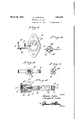
- Figure 1 is an elevational view showing the additional air supply valve incorporated in the intakemanifold.
- Figure 2 isa top plan view of the valve per se.
- Figure 3 is an end view observing the structure seen in Figure 2 from left to right.
- Figure 4 is a longitudinal section on the line 44 of Figure 2.
- j i Figure 5 is a horizontal section on the line 55 of Figure 4.
- Figure 6 is a plan view of a removable cover annulus.
- Figure 7 is an end elevation of the remov- V able valve seat ring.
- Figure 8 is a side view of the valve element itself.
- the improved is represented as a unit, by the TES OF CE.
- One of the ports 18 serves to accommodate theheaded end of the valve stem is mounted in an appropriate projects into a valve casing formed integral with oneside of Incidently, the part 20 socket extension as at I the adj acent ends ofthe coil spring spring surrounds the valve in. the casing and bearsat its periphery to provide stem, its opposite end against the valve head as shown in Figure 5 y
- This valve head comprises a guide 20 and 1 21 which is the casting.
- concentric conical projection 26 which constitutes alpilot which is projectable into the central'openingofthel valve seat'ring has margins. threaded and Y tapped into the screw threads 28 on the inner casing 21'. l-it -dia-" metrically opposite points,'the outer face of this valve ring 1s provided fwith constituting screw-driver kerfs 29. I meralBO represents a removable retain ng 'cap,
- valve seat ring is adjustable, and the :ad-
- the numeral-33 in Figure fi merely designates a removable annulus which as seen in Figure 4 constitutes the cover plate for the open top of'the cored channel 17. Particular emphasis is placed on the single casting 23 which defines the gasket-like body 16 with the annular channel'having its innerwa'll channel.
- the removable screen retaining cap 30 is important. "Likewiseithe 'adjustabilit-y of the 27 and the retaining set screw 30 is important. a
- valve seat ring Moreover, "the provision of the notched centralized conical extension constituting a the valve and spring 23'is a feature of cilitates manufacture.
Landscapes
- Engineering & Computer Science (AREA)
- Chemical & Material Sciences (AREA)
- Combustion & Propulsion (AREA)
- Mechanical Engineering (AREA)
- General Engineering & Computer Science (AREA)
- Characterised By The Charging Evacuation (AREA)
Description
March 29, 1932. -5, LUKS T 1,851,438
- AUXILIARY AIR VALVE filed novfz'i, 1930 v 2 Sheets-Sheet 1 Mi l Ill
A llomey March 29, 1932.
B. LUKS ETAL AUXILIARY AIR VALVE Filed Nov. 21, 1930 2 Sheets-Sheet 2 1 a 5 /jr2j ?/6 f/ w.
1/ 7 [a Inventor 1 Bzsalw/Z's A llomey appliance designed operating additional air inlet valve which in-.
Patented Mar. 29, 1932 1, UNITED ys TA IBLASELLUKS AND JOSEPH G.
AUXILIARY Application filed The purpose of the invention is to provide:
a suction-opened spring-closed automatically troduces supplemental air in aproperly and uniformly distributed manner to mingle with the fuel charge and to aid in vaporizing the charge, whereby to duction into the cylinders.
Our primary aim is to generally improve upon additional air supply devices of this general classification by providing a struc- 5 ture which is characterized by unusual simthe carbureted fuel charge to better fulfill the plicity in structural arrangement and parts, a device which serves to better proportion the amount of additional air in relation to the speed of the motor, and otherwise co-act with requirements of a valve of this species.
' In the drawings:
Figure 1 is an elevational view showing the additional air supply valve incorporated in the intakemanifold.
Figure 2 isa top plan view of the valve per se. 7 Figure 3 is an end view observing the structure seen in Figure 2 from left to right.
Figure 4 is a longitudinal section on the line 44 of Figure 2. j i Figure 5 is a horizontal section on the line 55 of Figure 4.
Figure 6 is a plan view of a removable cover annulus.
Figure 7 is an end elevation of the remov- V able valve seat ring.
Figure 8 is a side view of the valve element itself.
"generally denoted by intake manifold is designated at ll, and the the carbureter and provide a more eflicient I 2 and highly combustible mixture for introwithairdischargeports "This ring wall of the, cylindrical Figure 9is an end view of the valveelemenu' for holding the strainer screen mi vALvE November 21,1930. $eria1 1To. fl97,302.
seen in Figure 8observing it'f right.
'In the drawings,
the numer carburetor at 12} The improved is represented as a unit, by the TES OF CE.
rom left to I in Figure 1, the motor al 10. The
prises a'casting 16 gasket. Thiscasting is to provide a passage for wall around the opening is channel. The wall of The device 13 asshowninjFigure 5Comwhose configuration; re sembles that of'an ordinaryintake manifold i I centrally apertured fuel mixture and the channeled as at 17 to provide an air circulating and distributing i this channel is formed 18 circumferentially spaced to equalize and render the charge of air uniform for'incorporation with the u'pwardly passing column of gas.
' One of the ports 18 serves to accommodate theheaded end of the valve stem is mounted in an appropriate projects into a valve casing formed integral with oneside of Incidently, the part 20 socket extension as at I the adj acent ends ofthe coil spring spring surrounds the valve in. the casing and bearsat its periphery to provide stem, its opposite end against the valve head as shown inFigure 5 y This valve head comprises a guide 20 and 1 21 which is the casting.
is provided with a 22 to accommodate 23. This 1s confined disc-like flange T i'sprovided notches 25 in air intake passages.
There is a concentric conical projection 26 which constitutes alpilot which is projectable into the central'openingofthel valve seat'ring has margins. threaded and Y tapped into the screw threads 28 on the inner casing 21'. l-it -dia-" metrically opposite points,'the outer face of this valve ring 1s provided fwith constituting screw-driver kerfs 29. I meralBO represents a removable retain ng 'cap,
depressions The nu- 31 in placeff 10o 1 formation pilotyto facilitateiseatingof 7 I insure proper operation thereof underall e "circumstances; 'The provision o'fthe headed valverstem having screw-threaded connec- V ,tionofthevalve head and accommodating the mbly wh c e' had. T herefore,'a more lengthy description The valve seat ring is adjustable, and the :ad-
The numeral-33 in Figure fi merely designates a removable annulus which as seen in Figure 4 constitutes the cover plate for the open top of'the cored channel 17. Particular emphasis is placed on the single casting 23 which defines the gasket-like body 16 with the annular channel'having its innerwa'll channel.
Further,
and lateral extension of the ,part
21 which is-so shaped and desighedinternah Lounges otherlocated in a with the cylincylinder the inner face of which is engaged by the valve under the action of the spring.
BLASELUKS. JOSEPH e. LUKs.
We wishto emphasize the integral' ly and externally to providea casing to'ac .7
commodate the valve mechanism. Then too,
the removable screen retaining cap 30 is important. "Likewiseithe 'adjustabilit-y of the 27 and the retaining set screw 30 is important. a
valve seat ring Moreover, "the provision of the notched centralized conical extension constituting a the valve and spring 23'is a feature of cilitates manufacture.
A highly important-distinction to beob j served is the adjus table valve 'seat'ring' 27 "which canbe threaded inor out to regulate I the sensitivity of operation {of lthe springpressed valve head' Whereby to'permit positive controlling and properfproportioning ofthe air intake inrelation tothe fuel change andspeed. of the motor. 1
It isthought that thejdescription taken in is'thoughtunnecessary. M I WVhile the preferred embodimentoffthe'inflange, constituting the valvehead and the connection-with the drawings'will enableia I clearunderstanding of the lnvention tofl'be ve ntion'has been shown and described, it --is to be understood that minor changescoming' within the field ofinvention claimedmay be resorted torif desired. Q i, r
' -We claim:
nel therein the' inner wall ofwhi'ch ispen In testimony whereof we afiix our signa tures. 7 v apertured to afford uniform-;distribution'gof .the incoming air, together with the removable annulus forming a cover plate-for s'a'id loo? Anvauxiliaryfair intake va'lvedevice'deeigned for; incorporation betweenuntake inanlfold andcarburetor and-"comprising a i foratedto communicate with the intake-man- ,i-f'oljd,a flat extensiononjone' sideoffthebody,
a cylinder connected with Tthe outer end of gthefextension, a valve stem lpassingthrough the extensionand through one of the'perfor'avalve in the j'cyl- I e
Priority Applications (1)
| Application Number | Priority Date | Filing Date | Title |
|---|---|---|---|
| US497302A US1851438A (en) | 1930-11-21 | 1930-11-21 | Auxiliary air valve |
Applications Claiming Priority (1)
| Application Number | Priority Date | Filing Date | Title |
|---|---|---|---|
| US497302A US1851438A (en) | 1930-11-21 | 1930-11-21 | Auxiliary air valve |
Publications (1)
| Publication Number | Publication Date |
|---|---|
| US1851438A true US1851438A (en) | 1932-03-29 |
Family
ID=23976295
Family Applications (1)
| Application Number | Title | Priority Date | Filing Date |
|---|---|---|---|
| US497302A Expired - Lifetime US1851438A (en) | 1930-11-21 | 1930-11-21 | Auxiliary air valve |
Country Status (1)
| Country | Link |
|---|---|
| US (1) | US1851438A (en) |
Cited By (1)
| Publication number | Priority date | Publication date | Assignee | Title |
|---|---|---|---|---|
| US2969085A (en) * | 1953-10-16 | 1961-01-24 | Bosch Arma Corp | Non-chattering flow divider valve |
-
1930
- 1930-11-21 US US497302A patent/US1851438A/en not_active Expired - Lifetime
Cited By (1)
| Publication number | Priority date | Publication date | Assignee | Title |
|---|---|---|---|---|
| US2969085A (en) * | 1953-10-16 | 1961-01-24 | Bosch Arma Corp | Non-chattering flow divider valve |
Similar Documents
| Publication | Publication Date | Title |
|---|---|---|
| US1851438A (en) | Auxiliary air valve | |
| US1985192A (en) | Spark plug | |
| US2310594A (en) | Primer for internal combustion motors | |
| US1786283A (en) | Automatic air-inlet valve for internal-combustion engines | |
| US2210473A (en) | Combustion promoting device | |
| US1328235A (en) | Air-valve attachment for carbureters | |
| US1339014A (en) | Carbon-removing means for internal-combustion engines | |
| US1220419A (en) | Auxiliary air-supply device for motors. | |
| US1394687A (en) | Carbureter | |
| US1047015A (en) | Valve for explosive-engines. | |
| US1177318A (en) | Carbureter. | |
| US2347946A (en) | Valve for fuel saving devices | |
| US1342421A (en) | James chapman | |
| US2094978A (en) | Gas and air mixing device | |
| US1029606A (en) | Valve mechanism for carbureters. | |
| GB434173A (en) | Improvements in carburettors for internal combustion engines | |
| US1145172A (en) | Carbureter. | |
| US1196668A (en) | Carbureter. | |
| US1084954A (en) | Carbureter. | |
| US1119078A (en) | Carbureter. | |
| US1465154A (en) | Internal-combustion engine | |
| GB191324563A (en) | Improvements in Valves for Internal Combustion Engines. | |
| US1475862A (en) | Auxiliary air inlet for internal-combustion engines | |
| US1067623A (en) | Carbureter. | |
| GB152413A (en) | Improvements in carburetters for internal combustion engines |