US1851414A - Current control dumping device - Google Patents
Current control dumping device Download PDFInfo
- Publication number
- US1851414A US1851414A US569093A US56909331A US1851414A US 1851414 A US1851414 A US 1851414A US 569093 A US569093 A US 569093A US 56909331 A US56909331 A US 56909331A US 1851414 A US1851414 A US 1851414A
- Authority
- US
- United States
- Prior art keywords
- cylinder
- piston
- clock
- trigger
- current control
- Prior art date
- Legal status (The legal status is an assumption and is not a legal conclusion. Google has not performed a legal analysis and makes no representation as to the accuracy of the status listed.)
- Expired - Lifetime
Links
- 238000005192 partition Methods 0.000 description 9
- 239000004568 cement Substances 0.000 description 3
- 238000004804 winding Methods 0.000 description 3
- 239000000463 material Substances 0.000 description 2
- 240000002329 Inga feuillei Species 0.000 description 1
- HOKDBMAJZXIPGC-UHFFFAOYSA-N Mequitazine Chemical compound C12=CC=CC=C2SC2=CC=CC=C2N1CC1C(CC2)CCN2C1 HOKDBMAJZXIPGC-UHFFFAOYSA-N 0.000 description 1
- 210000004907 gland Anatomy 0.000 description 1
- XLYOFNOQVPJJNP-UHFFFAOYSA-N water Substances O XLYOFNOQVPJJNP-UHFFFAOYSA-N 0.000 description 1
Images

Classifications
-
- E—FIXED CONSTRUCTIONS
- E21—EARTH OR ROCK DRILLING; MINING
- E21B—EARTH OR ROCK DRILLING; OBTAINING OIL, GAS, WATER, SOLUBLE OR MELTABLE MATERIALS OR A SLURRY OF MINERALS FROM WELLS
- E21B27/00—Containers for collecting or depositing substances in boreholes or wells, e.g. bailers, baskets or buckets for collecting mud or sand; Drill bits with means for collecting substances, e.g. valve drill bits
- E21B27/02—Dump bailers, i.e. containers for depositing substances, e.g. cement or acids
-
- Y—GENERAL TAGGING OF NEW TECHNOLOGICAL DEVELOPMENTS; GENERAL TAGGING OF CROSS-SECTIONAL TECHNOLOGIES SPANNING OVER SEVERAL SECTIONS OF THE IPC; TECHNICAL SUBJECTS COVERED BY FORMER USPC CROSS-REFERENCE ART COLLECTIONS [XRACs] AND DIGESTS
- Y10—TECHNICAL SUBJECTS COVERED BY FORMER USPC
- Y10T—TECHNICAL SUBJECTS COVERED BY FORMER US CLASSIFICATION
- Y10T74/00—Machine element or mechanism
- Y10T74/11—Tripping mechanism
- Y10T74/114—Retarded
- Y10T74/116—Clock train
- Y10T74/118—Winding knob trip [e.g., alarm mechanism]
Definitions
- This invention also consists in certain other,
- Fig. 2 is a longitudinal. sectional view through the device with parts in elevation.
- Fig. 3 is a similar view but looking to-' wards the rear'part of the clock.
- Fig. at is a longitudinal sectional view look ing toward aside of the clock.
- Fig. 5 is an enlarged view of the rear of the clock showing the 'arm attached to the long winding stern and also showing portions of the trip armand a part'of the spring.
- Fig. 6 is a transverse sectional view'through' the piston.
- Fig. 7 is a diagrammatic view of the trigger arrangement.
- Fig. 8 is a view of the trip arm.
- v Fig. 9 is a view 01": the arm ttached to thelong winding stem. r
- the numeral 1 indicates the cylinder, the upper end of which is threaded to receive a collar 2 which couples the r is held in raised ofqthealarin mechanis niof the. clock;
- a partition 10 extends across the cylinder caught after dumping,--or bythe sides of' aj crooked hole;
- This cap or nose is formed anddividesthe-same'intonpper and lower I chambers, andxthe cylinder is provided with a pluralityof holes 11 "located above the (partition. .A cylinder ofcup-shape as shown at 12 is locatedin the upper chamber and-has a pluralityiof h0les'18 therein which register with: the holes 11when .the piston isin lowered 1 position,1so*that materialzsnchas'cement or the .likeplacediimthe tube 3fwill .pass throng thehole s ;1'3: and11 intothe-well. -f
- the device on cylinder. lzisattached-to the tube 3 and the stem or'other material is placed in thetube and is supportedtherein by the piston 12. j The device is then lowered into the well at any desired position,'it being of course understood that the c'lock mechanism is settooperate'the trigger. at any desired time: WVhen-this time occurs, the arm 20 is moved i'romnnder the trigger bar so I nism re set'so that that the'cy'linder drops and the holes l3 thereinare in register with theholes 11 in the cylinder, and thus the material will pass l through the holes into the well. The parts are then withdrawn and the trigger mechaover again.
- the device can be used.
- nism are located and a rod connected with the piston and entering said chamber.
- IBJAdevice'of the class described comprising a cylinder havinga partition therein
- A; dumping devicefor dumping cement and thel'ike inwells comprising a cylinder attached to'a chute for containing the cement, said cyllnd'er having holes therein, a, piston H in the cylinder having holes therein for registering with the first-mentioned holes when the piston is. in lowered-,positiom-the closed, chamber in the lower partof the cylinder, 21.
- a device of the class described compris- T inga cylinder having an opening therein, a
- pistoninthe cylinder having an opening therein for registering withfthe first-mentioned opening when the piston isin lowered "position,*triggermechanism for normally, holding jthe' piston in raised position, clock controlled mechanism for releasing the ;trig
Landscapes
- Life Sciences & Earth Sciences (AREA)
- Engineering & Computer Science (AREA)
- Geology (AREA)
- Mining & Mineral Resources (AREA)
- Physics & Mathematics (AREA)
- Environmental & Geological Engineering (AREA)
- Fluid Mechanics (AREA)
- General Life Sciences & Earth Sciences (AREA)
- Geochemistry & Mineralogy (AREA)
- Actuator (AREA)
Description
March 29, 1932. w, R M 1,851,414
CURRENT CONTROL DUMPING DEVICE William R/Idams flllorney Inventor v March 29, 1932. w ADAMS 1,851,414
CURRENT CONTROLY DUMPING DEVICE Filed Oct. 15, 1951 5 Sheets-Sheet 2 Inven for Wa'ZZz'am 7?. Adams Patented Mar. 29, 1932 7 WILLIAM B. Anni/rs, orrlewifnfiljokirliinomgf mri m nDet rmine "release the latch at such time and the piston will lower to dnmping position so that'themm terial will passthroughtheholes in-the piston and cylinder.
This invention also consists in certain other,
features of construction-andin the combination and arrangement of the several parts to be hereinafter i'ully described, -illustrated in the accompanying drawings and .zspecifically pointed out in the appended claims.
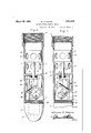
in describing the invention in detail, referenoe will be had to the accompanying drawings wherein like characters designate like or corresponding parts thruont the several views, and in which v Figure 1 is a view of the device attached to the lower end ofthe tube having a bail at its upper end. r
Fig. 2 is a longitudinal. sectional view through the device with parts in elevation. Fig. 3 is a similar view but looking to-' wards the rear'part of the clock. I
Fig. at is a longitudinal sectional view look ing toward aside of the clock. Fig. 5 is an enlarged view of the rear of the clock showing the 'arm attached to the long winding stern and also showing portions of the trip armand a part'of the spring.
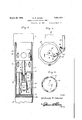
Fig. 6 is a transverse sectional view'through' the piston.
Fig. 7 is a diagrammatic view of the trigger arrangement. Fig. 8 is a view of the trip arm. v Fig. 9 is a view 01": the arm ttached to thelong winding stem. r
Inthese drawings, the numeral 1 indicates the cylinder, the upper end of which is threaded to receive a collar 2 which couples the r is held in raised ofqthealarin mechanis niof the. clock;
"iuppe r end-.o f the cylinder .pipeio ihavihg a collar- 4 atits upperend to receive itball t to whichabaileriline e is attach'ed. ,r e
flower end-10f :the cylinderisflprovided with fine threadsfto receive the- 'thrcad'e d part 7,
01" a' cap 8. which is ron'ndedlas shown, so as to LglildBjillh device down through the hole or well without'dangerof,the device being 'with'a transverse hole 9 so thata baror the like can:bepassed therethroufgh in order that the capor. nose canbe threaded tightly into the lower end of the cylinder.
E A partition 10 extends across the cylinder caught after dumping,--or bythe sides of' aj crooked hole; This cap or nose is formed anddividesthe-same'intonpper and lower I chambers, andxthe cylinder is provided with a pluralityof holes 11 "located above the (partition. .A cylinder ofcup-shape as shown at 12 is locatedin the upper chamber and-has a pluralityiof h0les'18 therein which register with: the holes 11when .the piston isin lowered 1 position,1so*that materialzsnchas'cement or the .likeplacediimthe tube 3fwill .pass throng thehole s ;1'3: and11 intothe-well. -f
iOf course when the pis'ton i s ra sed po 3 sition nth-Q hole; 13 visiout of =ali n'ernentwith the hole 11: and materialcannot escape. llhe pistonrod. 14? passes-through aspacking gland 15 carried by the partitionand the trigger iba'rlfi is pivoted toa .hangerl'i carried by the partition for extending under the lower Nendaot the rod 1'4: :tohold the piston in "raised position.. Avtriggeraarrn 18,7 of the shape other; end of the a-rm -.20Q fitsi over a .eanr 122 -attached to-thealarm windingstem of clock.
23,:the handle of the-stem=.bein-g-;showntat24. :.-A;bracket:25 attached to the; rear face of, the
1 decr ases a brace {for the winding stein shown in. Fig; 18, is ;pivoted to-a part Qui e 4 s one-end;pivotedtofthe lower"; r
Ylo. V. .where the ClOOk'lS located.
' outer end of the arm and its other end '7 is attached to a part 27 which forms part of the supporting means of the clock.
Other portions of the clock supporting means is shown at 28 and extends between the'partition and the nose of cap 8 and a gasket29 is placed between the nose or cap 8 and the lower end of this cylinder make a' water tight joint between the two parts so that. no moisture can enter "the chamber From" the foregoing it will bebseen, that;
after the parts are set as fsh'own i'n' FigsfQ and 3, the device on cylinder. lzisattached-to the tube 3 and the stem or'other material is placed in thetube and is supportedtherein by the piston 12. j The device is then lowered into the well at any desired position,'it being of course understood that the c'lock mechanism is settooperate'the trigger. at any desired time: WVhen-this time occurs, the arm 20 is moved i'romnnder the trigger bar so I nism re set'so that that the'cy'linder drops and the holes l3 thereinare in register with theholes 11 in the cylinder, and thus the material will pass l through the holes into the well. The parts are then withdrawn and the trigger mechaover again.
Attention is. called to the tact that this 'device'fwill dump its-load wherever necessary, "andit is not necessary-to lower the device to the bottom of the well, and by controlling the fdumping'by the clock mechanism the device can be positioned wherever it is desired, as sufiicient tnneis provided ffOI properlyadusting" the 'devicebefore the dumping act. 7
s It is thougnt 'from'the foregoing descrip- *tion that the advantages and novel features scope of the appendedclaims. I Havingthns described my invention, what connected with its upper end. L
the devicecan be used.
nism are located and a rod connected with the piston and entering said chamber.
IBJAdevice'of the class described comprising a cylinder havinga partition therein, and
an opening in the cylinder above the partition, pistons in the cylinder above the parti-Y tion and havingan opening thereinfor registering. with the first-mentioned opening when V the piston has been lowered, a rodconnected with the piston and extending through the partition, a packing-gland surrounding the rod, a trigger bar pivoted in the cylinder below the partition, atriggerarm pivoted in they cylinder below the partition for holding the trigger bar in raised position with the piston in raised position, clock mechanism for moving thetrigger arm to releasing posi- -tion, a nose member threadedin thelower end of,v the cylinder for closing the lower; end
thereof, and means forattaching the upper endlof thecylin der' to atube having a bail a. A; dumping devicefor dumping cement and thel'ike inwells, comprising a cylinder attached to'a chute for containing the cement, said cyllnd'er having holes therein, a, piston H in the cylinder having holes therein for registering with the first-mentioned holes when the piston is. in lowered-,positiom-the closed, chamber in the lower partof the cylinder, 21.
rod connected with the piston at the end of" the. chamber, trigger means in the chamber for engaging the rod for holding the piston q nism at anydesired time, and a nose threaded.
. in. the lower end of the cylinder for closing thelowerend of the chamber. 7 V r In testimony: whereof I afiix my signature; 7 WILLIAM R. ADAMS;
' f 1; A devic'eof the class described comprisf Ti y havin 'an opening therein, a
piston in the cylinder having an opening therein for registering with'the first opening when the piston-is in lowered position, trigger in raised position, clock mechanism in said chambers for releas ngthe trigger mecha- *mechanism for holding the piston in-raisedposition and. time controlled mechanism for releasing'the trigger mechanisnn V v 2. A device of the class described compris- T inga cylinder having an opening therein, a
pistoninthe cylinder having an opening therein for registering withfthe first-mentioned opening when the piston isin lowered "position,*triggermechanism for normally, holding jthe' piston in raised position, clock controlled mechanism for releasing the ;trig
ger mechanism, a 'closed chamber in the cyl-v inder-in 'wliichthe clock' a-nd'trigger mecha 1'
Priority Applications (1)
| Application Number | Priority Date | Filing Date | Title |
|---|---|---|---|
| US569093A US1851414A (en) | 1931-10-15 | 1931-10-15 | Current control dumping device |
Applications Claiming Priority (1)
| Application Number | Priority Date | Filing Date | Title |
|---|---|---|---|
| US569093A US1851414A (en) | 1931-10-15 | 1931-10-15 | Current control dumping device |
Publications (1)
| Publication Number | Publication Date |
|---|---|
| US1851414A true US1851414A (en) | 1932-03-29 |
Family
ID=24274073
Family Applications (1)
| Application Number | Title | Priority Date | Filing Date |
|---|---|---|---|
| US569093A Expired - Lifetime US1851414A (en) | 1931-10-15 | 1931-10-15 | Current control dumping device |
Country Status (1)
| Country | Link |
|---|---|
| US (1) | US1851414A (en) |
Cited By (1)
| Publication number | Priority date | Publication date | Assignee | Title |
|---|---|---|---|---|
| US2757742A (en) * | 1954-11-12 | 1956-08-07 | Sun Oil Co | Reagent well feeder |
-
1931
- 1931-10-15 US US569093A patent/US1851414A/en not_active Expired - Lifetime
Cited By (1)
| Publication number | Priority date | Publication date | Assignee | Title |
|---|---|---|---|---|
| US2757742A (en) * | 1954-11-12 | 1956-08-07 | Sun Oil Co | Reagent well feeder |
Similar Documents
| Publication | Publication Date | Title |
|---|---|---|
| US1851414A (en) | Current control dumping device | |
| US1297344A (en) | Fish-spear. | |
| US2238384A (en) | Pneumatic amusement machine gun | |
| GB1131402A (en) | Improvements in electric circuit breaker with voltage controlling resistance | |
| US1501303A (en) | Valve | |
| US1753513A (en) | Excavator-dipper latch | |
| US1703077A (en) | Electromagnet-controlling means | |
| DE925337C (en) | Machine gun as gas pressure loader with pre-ignition | |
| US1535878A (en) | Grab bucket | |
| US1902691A (en) | Excavating machine | |
| US1824445A (en) | Knitting needie | |
| KR810002147Y1 (en) | Electric latch | |
| US1557773A (en) | Fuel-feeding apparatus | |
| US2095322A (en) | Trip mechanism for dumping buckets | |
| US1392024A (en) | Drop-down gun and rifle | |
| US2172099A (en) | Paste tube closure | |
| US1064604A (en) | Automatic tap-hole stopper. | |
| US1890671A (en) | Foot control for mechanically operated gas and smoke discharge systems for daylight holdup robberies | |
| DE818410C (en) | Single rope grab | |
| US1399193A (en) | Fly-swatter | |
| US1848942A (en) | Joseph fautaci | |
| US1324498A (en) | Device eok | |
| US2429457A (en) | Time-delay electric switch | |
| US639149A (en) | Windlass water-elevator. | |
| US1970501A (en) | Firearm |