US1851409A - Rail joint shim device - Google Patents
Rail joint shim device Download PDFInfo
- Publication number
- US1851409A US1851409A US575610A US57561031A US1851409A US 1851409 A US1851409 A US 1851409A US 575610 A US575610 A US 575610A US 57561031 A US57561031 A US 57561031A US 1851409 A US1851409 A US 1851409A
- Authority
- US
- United States
- Prior art keywords
- rail
- head
- rails
- shim
- shim device
- Prior art date
- Legal status (The legal status is an assumption and is not a legal conclusion. Google has not performed a legal analysis and makes no representation as to the accuracy of the status listed.)
- Expired - Lifetime
Links
- 238000009413 insulation Methods 0.000 description 5
- 239000011810 insulating material Substances 0.000 description 4
- 239000002184 metal Substances 0.000 description 3
- 238000010276 construction Methods 0.000 description 2
- 239000000463 material Substances 0.000 description 2
- 241001674048 Phthiraptera Species 0.000 description 1
- 101100439111 Rattus norvegicus Cebpd gene Proteins 0.000 description 1
- 238000004519 manufacturing process Methods 0.000 description 1
- 229920000136 polysorbate Polymers 0.000 description 1
- 239000004576 sand Substances 0.000 description 1
Images
Classifications
-
- E—FIXED CONSTRUCTIONS
- E01—CONSTRUCTION OF ROADS, RAILWAYS, OR BRIDGES
- E01B—PERMANENT WAY; PERMANENT-WAY TOOLS; MACHINES FOR MAKING RAILWAYS OF ALL KINDS
- E01B11/00—Rail joints
- E01B11/54—Electrically-insulating rail joints
Definitions
- This invention relates to a-novelshim deviceifor use in producing insulated joints for so-called headfree rails.
- a so -calledheadfree rail derives its name on theone hand from the fact that its head is of inverted truncated pyramidical shape in cross section and, on the other hand, I from the .fact that when two such rails are joined together thesplice bars 1 'take loading engagement at their inner upper cornerswith the head fillets of therails andhave; clearance outwardly of said fillets from the under sides oflthe rail heads. While rails and j oints of this character are extremely de-.
- the. general object of the present invention is, to provideashimdevice for use with headfree rails to, in effect, convert the headsof such rails tothestandard or'head fishingcontact type, thus to provide for the useof s lice bars and insulating joints of the head fis ing contact type in'the splicing of headfree rails to obtainthe advantages of the relatively extensive bearing areas for; the insulating material afforded by joints of this type.
- yide a shim device for the purpose mentioned; 40 which may be economically produced from sheet metal: and'gwhich embodiesa novel construction forcooperation with railsj of the headfree type manner toefi'ectively fsusa ,tain loads'imposed on the rails and transmitted through the shim deviceto the insulating material and the splicebar;
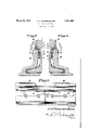
- Figure 1 is a transverser'section through an insulated joint for headfree rails illustrating" the use of the "present shim device according ;to one-practical embodimentof the same.
- v Figure 2 is a side elevation-,of-the joint; illustrated inQFig. 1 withfthe splicebar removed; and V F ur 3 i trating a, shim device of slightly; alternative form; Referring view similarto I to the drawing sin detail, T
- vAnother object of the. invention is to proand the upper inner corner ofthej splice;
- tact type andthe production of an insulated this respect is to extend the portion 17 downjoint of the head fishing contact type in which Wardly and inwardly at such anangle relative v the insulation I has relatively extensive bearto the flange portion 14 that when the latter 'ing areas cooperati'ng with the shim device portion is disposed at the roper angle rela and thespli'ce bar, respectively, so that the I tive to the rail the upper ace of the portion 70 load is distributed over a substantial area 17 bears flat against the inclined" rail head of the insulation with consequentp'rplonga; surface thusgto afiord arelativel y eflenv y ti f fly ⁇ ; lifgft'h e' insulation.
- topof thritin'forcing rib termed by turning? 9 to alg -es the Web the r s. a
- flangeimitionqaiagainstupward move' iinvf i and efi' I y: irs i and holdsthejsarne iflcorrectjrelatioii't'oQth a g a e o hsnsl l l wm fierakt top or; the"spli' -:e' baf'andthe int rpbs'edin i e 'i ibtween Sand i ii d 3 relative r to the rail; for 'c oi'iectfl cooperation ofyvhich py; iw thi.thae top of thesplicebanand thej'inter rairiidical.
- a shim device as set forth in claim 2 in which the free edge of'the downwardly and inwardly bent portion of the shim has the flange portion.
- a shim device as in which the free edge of the downwardly and inwardly bent portion of the shim is chamfered and has flat surface contact with the upper face of the flange portion.
Landscapes
- Engineering & Computer Science (AREA)
- Mechanical Engineering (AREA)
- Architecture (AREA)
- Civil Engineering (AREA)
- Structural Engineering (AREA)
- Insulators (AREA)
Description
March 29,1932
E. F. SCHERMERHORN RAIL JOINT SHIM DEVICE Filed NOV. 17, 1931 ZHI fi gwuentoz E1? Schernwrlwrzu l atented Mar. 29, 1 932 nnwnnns'r. sonnniannnonn, OF BROOKLYN, new YORK, nssrenon' To THE {1min Jenn comrnmcor NEW- YORK, 1\T.'Y., A coRPoaA'rIono NEW YORK RAILfJoINT SHIM nnvrcn 7 Application filed November 17,1931. Serial 'No. 375,610.
This invention relates to a-novelshim deviceifor use in producing insulated joints for so-called headfree rails. a
As is well known, a so -calledheadfree rail derives its name on theone hand from the fact that its head is of inverted truncated pyramidical shape in cross section and, on the other hand, I from the .fact that when two such rails are joined together thesplice bars 1 'take loading engagement at their inner upper cornerswith the head fillets of therails andhave; clearance outwardly of said fillets from the under sides oflthe rail heads. While rails and j oints of this character are extremely de-. sirable and advantageousfrom many difier entviewpointsgit has been foundthatwhenjinsulating material is interposed the upper innerfcorners of thesplice bars and the head Y fillets of the rails the insulation-tends quick; 2o ly to crush'and disintegrate due to concentration-of the load on a relatively small ,area -of the, insulation. Therefore, inproducing :insulated rail joints forheadfree rails it is desirable .to provide means whereby-the load;
sustaining portion of the insulating material shall have relatively extensive bearing areas. Accordingly, the. general object of the present invention is, to provideashimdevice for use with headfree rails to, in effect, convert the headsof such rails tothestandard or'head fishingcontact type, thus to provide for the useof s lice bars and insulating joints of the head fis ing contact type in'the splicing of headfree rails to obtainthe advantages of the relatively extensive bearing areas for; the insulating material afforded by joints of this type. I I
yide a shim device for the purpose mentioned; 40 which may be economically produced from sheet metal: and'gwhich embodiesa novel construction forcooperation with railsj of the headfree type manner toefi'ectively fsusa ,tain loads'imposed on the rails and transmitted through the shim deviceto the insulating material and the splicebar;
With the. foregoing and other objects in view, will becomemorefully apparentasthe nature of the invention is better understood, the same consists in the novel construction and inthe novel combination and armore fully described, illustrated in the accompanying rawings and defined in theap pendedclaimsfl r l In the drawings :v
i rangement of features as will be hereinafter 1 Figure 1 is a transverser'section through an insulated joint for headfree rails illustrating" the use of the "present shim device according ;to one-practical embodimentof the same.
vFigure 2 is a side elevation-,of-the joint; illustrated inQFig. 1 withfthe splicebar removed; and V F ur 3 i trating a, shim device of slightly; alternative form; Referring view similarto I to the drawing sin detail, T
he observed that while'therails, designated as R, are of the headfree =typ,e,-theinsu-'l lated oint is of the; head fishing,contact well-known type having the :sides of their areas for; the insulatin material whereby 'longevityof the jointi-s assured; f The ;headfr,-ee rail illustrated are of the v 75." heads, beginningv at points spaced d'ow nwardly' from theirtop, surfaces, inclined in-- wardly asat 10 and Imergingjinto'the usual rail :headfillets 11. qordinarilya joint bea tween two rails of this type isvlefiected-hy means of a splice barwhich, at'its head, 5
takes loading engagement solely-at its inner;
upper corner with the head fillets ofthe rails provided between two such'irails it is not" satisfactorymerely to interpose alayer pf v V v insulation-betweentheheadlilletsoif the-rails: vAnother object of the. invention is to proand the upper inner corner ofthej splice;
,:When, however, an insulated jointyisto bef. 4 i
within the limitsiof the head fillets of the? arm-sa preferably in I two. separate sections.
feet, Convert the rails to the head fishing use of a splice bar B of the 'head fishing co'nrailssoon results in crushing and disintegraai". I tlon ofthe'insulatlon. Therefore, according to.thepresentunventmh, a shim device S,: v
'; 8, s one ,for cooperation with" each rail, is i f prov ded to seat a-galnstgtherails to, inef-xqr: 4
contact type." 'lhu s,zprovision is madefo'r the: g 1%: i
III
tact type andthe production of an insulated this respect is to extend the portion 17 downjoint of the head fishing contact type in which Wardly and inwardly at such anangle relative v the insulation I has relatively extensive bearto the flange portion 14 that when the latter 'ing areas cooperati'ng with the shim device portion is disposed at the roper angle rela and thespli'ce bar, respectively, so that the I tive to the rail the upper ace of the portion 70 load is distributed over a substantial area 17 bears flat against the inclined" rail head of the insulation with consequentp'rplonga; surface thusgto afiord arelativel y eflenv y ti f fly}; lifgft'h e' insulation. s.v sive contact areabetween-- the-shim section 10 h rawin s, ttwill bglo ser ed hatfi Referring particularlyto Figs. lnand.2..,. andwsaidirail surface. r p g mesaneiteaabe fi siafibl a. J e p i -iif 1:8 th.. .e g i h ll l ii lt Newsst n '7 are, except "for their-' right'fa left Hand su'st {riboftheflangd orfion 14 by s .'form; duplicates of each other and-that each ro ling-.pntgrning the metal of the flange section is formed from suitable shaman portion a but a core forming rod 18 as illus- 15 to provide a vertical body pqrtion 12 to liegtratedsin Figs-1oiithegllzawings, particularly against the rail Web, a curved portion-13 in instances Where the metal of the shim secto'fitfthe hea'd filletof the raiL -and a flange tions is coinp'arativelythin. Om-the other; portion 14-. f extending outvvai'd fr'orn' thehand,-thisi cor is not essential and mayre'ad curved iportion l3ilto" underlie the rail hcad il be dispensed with, as illustrated in -Fyrg 3 V andxto' afilordiatwitsundersidea relatively o l the""drawing articularly ininjstances g extensive flat bearing area similar the" Where the shim ections are formed gof 'relafishing surface at the undersideTof-a rail Qlyf 1 'heavyw'sheety-mtdli IMQ I of'th yvellknovvnstandardtype. over as aforesaid thefree edgeioi tha'por g ,"Lh'e' splice bar B used With the present tion ma in any'jnstance"coiitact vvith pr shinfdevice is, as aforesaid, "and" as iI-Iusbe spaced frorn'the top of the flange portionfgo praised-tin the" drawing 'ofthe head fishin '1 an'din' either eve jzi f q pe al or g contact type-having afl'at top surface form said. =f1 ee ed ge fis -required; as is'appariitf operation wit'h the flange portions; 14' of the i om thQ- flhl trationinFig-lgth fi' w shimgsection s, and the insulation'f l is 'ing I1g i 0 h' rii gf' lf edge-0 F 50 itself cbntacts with" the inclinedsidesnr j ;;,.twe'e'n i*andhaving surface contact-ivithfihe i (1'ini ii'g 3 =for su 1f celf id ct ithiflxy flange; portions 14.of the shim.sections and 'llpp a e ft 'fl ngeport nthertop loathe neepalg respectivtlyg Without iurthela*de ri ti fitas thoii'ght -Q n In order to adapt ,the flangie poi-eiil .14 i that th ea mq n d an a t th'ei I of the shimsectipn' sto sustain 1ea ifi cl jverftioir will bs readil f-ap ijnteto tho ejgog j thereo'n, -iIQeK,iir'brdrftoisupport said po tions againstjupwardmovementintd the" n e q t e es n i fl a ez; r0 1 voids or'"vacant spacesexisting a't th'e under jportion and minor details of ycons't'ructio Sides of the rail head'sg under-the; influence ay e res t t ii he i iii art g iQiQ-i l i .40 ofil'oads imposed on'the'joi'rit, the 'sa'id flfifig e he sp i -t e m ti n; n gs qpg, sim an,
' ;portion of each shirasectioiijis rlIedfltifiapp cl ims-f f as indicated at l6; -a'iid then exiten d-d down %s fi. e e-f u e p o u T 3 5f.
wardly "and' invvardilfijas jindiatedfatjU," at d jq s-" ll d eefa lethihea the"hpperffaee of'th'e fiangeportionljthear l P o }se iqei mn risw as rangernent'ifithis respect'being 'such that-the h d nq a fi emb .i clusiv i @FQQI :1
topof thfrein'forcing rib termed by turning? 9 to alg -es the Web the r s. a
. flangeimitionqaiagainstupward move' iinvf i and efi' I y: irs i and holdsthejsarne iflcorrectjrelatioii't'oQth a g a e o hsnsl l l wm fierakt top or; the"spli' -:e' baf'andthe int rpbs'edin i e 'i ibtween Sand i ii d 3 relative r to the rail; for 'c oi'iectfl cooperation ofyvhich py; iw thi.thae top of thesplicebanand thej'inter =rairiidical. shape incross section}; corripri'si splice bar; said I flange portion '7 he iirg belifiiiztl nliisivs i i. a?! J... .1.
portion to lie against the web of the rail, a
V flat surface contact-with the upper face of i i curved portion to fit the head fillet of the rail, and a flange portion extending outward from said curved portion to underlie the rail head and to afford a relatively extensive bearingarea for the insulating material to be interposed between said shim and the splice bar, the marginal part of said flange portion being bent upwardly and inwardly and then downwardly and inwardly for fiat surface engagement with the inflange upon itself in the manner stated.
5. A shim device as set forth in claim 2 in which the free edge of'the downwardly and inwardly bent portion of the shim has the flange portion.
6. A shim device as in which the free edge of the downwardly and inwardly bent portion of the shim is chamfered and has flat surface contact with the upper face of the flange portion.
In testimony whereof I hereunto afiix my V signature.
EDWARDS F. SGHERMERHORN'.
"set forth in claim
Priority Applications (1)
| Application Number | Priority Date | Filing Date | Title |
|---|---|---|---|
| US575610A US1851409A (en) | 1931-11-17 | 1931-11-17 | Rail joint shim device |
Applications Claiming Priority (1)
| Application Number | Priority Date | Filing Date | Title |
|---|---|---|---|
| US575610A US1851409A (en) | 1931-11-17 | 1931-11-17 | Rail joint shim device |
Publications (1)
| Publication Number | Publication Date |
|---|---|
| US1851409A true US1851409A (en) | 1932-03-29 |
Family
ID=24300999
Family Applications (1)
| Application Number | Title | Priority Date | Filing Date |
|---|---|---|---|
| US575610A Expired - Lifetime US1851409A (en) | 1931-11-17 | 1931-11-17 | Rail joint shim device |
Country Status (1)
| Country | Link |
|---|---|
| US (1) | US1851409A (en) |
-
1931
- 1931-11-17 US US575610A patent/US1851409A/en not_active Expired - Lifetime
Similar Documents
| Publication | Publication Date | Title |
|---|---|---|
| US1851409A (en) | Rail joint shim device | |
| GB267832A (en) | Improvements in interengaging blocks and the like for floors, roads and the like | |
| US1730067A (en) | Expansion joint | |
| US1814476A (en) | Rail structure | |
| US1455695A (en) | Rail joint | |
| US2176574A (en) | Parting strip for roadways or the like | |
| US1472157A (en) | Rail joint | |
| US1629750A (en) | Road strip | |
| US1683432A (en) | Insulated rail joint | |
| US1815373A (en) | Joint for concrete slabs | |
| US1517124A (en) | Rail joint | |
| US708901A (en) | Tramway-rail. | |
| US1736328A (en) | Insulated rail joint | |
| US1549788A (en) | Rail joint | |
| US1477838A (en) | Metallic beam splice | |
| US1499199A (en) | Railroad tie | |
| US1489238A (en) | Rail support and tie protector | |
| US2100947A (en) | Step joint | |
| US1707048A (en) | Rail joint | |
| US1617760A (en) | Noiseless rail joint | |
| US1833375A (en) | Concrete railroad tie | |
| US1612633A (en) | Rail joint | |
| US549154A (en) | Rail-joint | |
| US1164974A (en) | Insulated rail-joint. | |
| US1769651A (en) | Insulated rail joint |