US1851407A - Cooling system - Google Patents
Cooling system Download PDFInfo
- Publication number
- US1851407A US1851407A US459692A US45969230A US1851407A US 1851407 A US1851407 A US 1851407A US 459692 A US459692 A US 459692A US 45969230 A US45969230 A US 45969230A US 1851407 A US1851407 A US 1851407A
- Authority
- US
- United States
- Prior art keywords
- water
- jacket
- tank
- level
- engine
- Prior art date
- Legal status (The legal status is an assumption and is not a legal conclusion. Google has not performed a legal analysis and makes no representation as to the accuracy of the status listed.)
- Expired - Lifetime
Links
- 238000001816 cooling Methods 0.000 title description 13
- XLYOFNOQVPJJNP-UHFFFAOYSA-N water Substances O XLYOFNOQVPJJNP-UHFFFAOYSA-N 0.000 description 104
- 238000009835 boiling Methods 0.000 description 11
- 238000007599 discharging Methods 0.000 description 11
- 238000002485 combustion reaction Methods 0.000 description 7
- 230000005587 bubbling Effects 0.000 description 6
- 239000012530 fluid Substances 0.000 description 5
- 238000004519 manufacturing process Methods 0.000 description 5
- 238000010438 heat treatment Methods 0.000 description 2
- 206010037660 Pyrexia Diseases 0.000 description 1
- 239000000945 filler Substances 0.000 description 1
- 238000005187 foaming Methods 0.000 description 1
- 238000013021 overheating Methods 0.000 description 1
- 238000010792 warming Methods 0.000 description 1
- 239000002699 waste material Substances 0.000 description 1
Images
Classifications
-
- F—MECHANICAL ENGINEERING; LIGHTING; HEATING; WEAPONS; BLASTING
- F01—MACHINES OR ENGINES IN GENERAL; ENGINE PLANTS IN GENERAL; STEAM ENGINES
- F01P—COOLING OF MACHINES OR ENGINES IN GENERAL; COOLING OF INTERNAL-COMBUSTION ENGINES
- F01P11/00—Component parts, details, or accessories not provided for in, or of interest apart from, groups F01P1/00 - F01P9/00
- F01P11/02—Liquid-coolant filling, overflow, venting, or draining devices
Definitions
- My present invention relates to cooling systems adapted for use with internal combustion engines and particularly to those adapted to operate by the boiling and condensing cycle. In some aspects it may be considered as an improvement or rather as a difierent and improved solution of some of the problems involved in practical operation of the apparatus shown in my. prior Patent v 1,378,724, granted May 17,1921.
- a characteristic feature is that boiling water or steam from the water jacket of the engine is discharged into the base of the radiator so that in full operation the cooling is by upflow of steam, with more or less of the boiling water into the core or honeycomb of the radiator.
- One of the difliculties is that whenever the cooling system is oper- 0 ated under full load conditions, which may result from, idling with an insuflicient fan, long continued high speed operation or heavy load operation or operation in very hot weather or in high altitudes, the steam and boiling water discharged in the base of the radiator causesbubbling and foaming to such an extent that too much of the water is driven upward through the core or honeycomb, thereby leavinginsufficientwater for circulation through the water jacket.
- My present invention relates to the same problems, but affords a different solution.
- the water and steam from the top of the water jacket are discharged into the base of the radiator as before, but the only return path for the water is from the top tank of the radiator, preferably from a point substantially above the bottom of said tank and preferably about the level of the top of the water jacket of.the engine so that a'very substantial depth of water must be stored in the top tank before it submerges the intake of the pump.
- the horizontal section of the top tank is great enoughso that the amount as well as the depth of the water in the tank, is very substantial, but as will be explained, it is the high and resulting water level in the upper tank that is important.
- This is in contrast to my said Patent 1,501,065, in which latter the water is trapped in the upper tank and the shunt path for water therefrom drains from the bottom thereof.
- the present invention involves connecting the pump intake to the upper tank of the radiator at above the normal or cold level of the water in the system, so that while the engine is heating up there will be no water sent to the jacket by the pump and heating'up "m will therefore be more rapid than in any of the systemsof my prior patents.
- the water levelin the top tank will rise and thereafter the pump will receive water, so long as conditions cause the water to remain above the level of the intake.
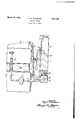
- the figure is a side elevation, partly m section, showing my system as applied to an automobile engine and radiator.
- the motor is conventionally indicated as including the usual crank case 1 and cylinder block 2, the upper parts of which are enclosed by water jacket 3.
- the water cooling system is conventionally indicated as including the radiator 4, ⁇ located as usual on the same level with the motor and directly in front of it, so that the lower part of the radiator is below the level of the water jacket of the motor.
- the circulation of the water from the top tank 15 of the radiator is through a pipe 5 to pump 6, the latter being preferably driven from the engine at directly proportionalspeed.
- the pump is indicated as being a gear pump, but this is merely to illustrate that the pump is one adapted to receive the water and force it into the water jacket against friction and any back pressure discharges through a pipe 7, preferably into the top of the water jacket 3, whence the path of flow is through a riser outlet 8, and downwardly extending return pipe 9 which discharges into the bottom tank 12 of the radiator.
- the pipe 7 contains a check valve 10 to insure against back flow of water or steam such as might otherwise occur under operating conditions I when the engine and pump are stopped.
- This valve islocated a substantial distance above the level of the pump 6, so that the output side of the pump will always be submerged in a substantial amount of water, even when the intake of the pump is above the water level for considerable periods of time. This keeps the pump primed and lubricated.
- the return pipe 9 discharges through a horizontal portion which may extend lengthwise of the lower tank 12 of the radiator and may terminate in a discharge device 14, which may consist of many layers of gauze, as described in said Patent 1,694,397.
- the core or honeycomb 16 is of less height than customary in present-day automobile radiators, and the upper tank 15 is very much higher, the proportions of core and upper tank being more nearly such as indicated in my said Patent 1,501,065.
- the bottom of the upper tank 15 is substantially below the desired initial level of water in the engine jacket 3, when the latter is full; the intake level 5a is substanthe object being to have a very substantial storage space into which a substantial part of the total'water of the system may rise above taln 5a under extreme conditions of hightemperature, hard-boiling.
- the tank may be provided with the usual filler closure 18 and waste overflow pipe 17.
- a cock 20 at the desired normal or cold water level in the systenf, which is ordinarily the top of the water jacket cavity of the engine.
- This cock may be open when the system is to be filled with water so that the operator may observe when the desired water level is reached and particularly may be able to drain off any excess incidentally introduced. Except during filling, the cock remains closed.
- the tank 15 was about 10 inches high, the test cock 20 about 2 inches above the bottom thereof and the intake 5a about 2 inches above the test cock;
- the only water to be heated when the engine is started is the water in the jacket 3, of the engine. This quickly comes to boiling and steam only is discharged into the bottom tank 12 until all the water in the core has been heated to boiling and the steam evolution has become great enough to create a lively bubbling upflow of steam in the narrow passages of the core, thereby lifting water upward and raising the level of the water above the intake 5a.
- This warming up period involves no hazard and does not require that the normal level of water at starting be as high as the test cock 20.
- the range of water rise and fall is so wide that with the engine running idle, below the test cock, still so long as any water remains or appears in the top tank 15, the amount boiling ofi by the engine before there can be any danger of running dry will be sufficient to insure boiling in the radiator and rise of the level above pump intake, 5a, it being a fact that so long as any appreciable amount of water remains in the engine jacket, the engine will not overheat.
- An internal combustion engine having a water jacket and a water cooling system therefor, including aradiator comprising a low level distributor tank of relatively small volume, an intermediate air cooled core having relative thin passages for upfiow of fluid to be cooled and an upper tank of substantially greater vertical height and greater volume than said lower tank, extending belowand a substantial distance above the normal level of the water in the engine jacket; conduit means leading from the top of the engine jacket and discharging substantially all the steam and water from said jacket into said low level distributor in upflow relation to the bottom of said core and a water pump discharging into said jacket and having its tank having relatively large storage capaclty.
- An internal combustion engine having a water jacket and a water cooling system therefor, including a radiator comprising a low level distributor tank of relatively small volume, an intermediate air cooled core having relatively thin assages for upflow of fluid to be cooled and an upper tank of substantially greater vertical height and cater volume than said lower tank, extending below and a substantial distance above the normal level of the water in the engine jacket;
- An internal combustion engine having a water jacket and a water cooling system therefor, including a radiator comprising a low level distributor tank of relatively small volume, an intermediate air cooled core having relatively thin passages for upflow of fluid to be cooled and an upper tank of substantially greater vertical height and greater volume than said lower tank, extending below and a substantial distance above the normal level of the water in the engine jacket; conduit means leading from the top of the engine jacket and discharging substantially all the steam and water from said jacket into said low level distributor in upflow relation to the bottom of said core and a water pump discharging into said jacket and having its intake connected to the upper tank at a point a suificient distance above the normal water level therein so that it will not take water except when and while active bubbling and steam production in the water jacket is forcing water upward through the core into the upper tank and holding it at or above the level of said intake, and an overflow drainage cock located a substantial distance below the level of said pump .therefor, including a radiato intake, to prevent filling of the system to the level of said intake
- An internal combustion engine having a water jacket and a water cooling system r comprising a low level distributor tank of ,relatively small volume, an intermediate air cooled core having relatively thin passages for upflow of flllld to be cooled an an upper tank of substantially greater vertical height than said lower tank extending a relatively great dis tance above the normal level of the water in the engine jacket; and auxiliary water circulating means including conduit means leading from the top of the engine jacket and discharging substantially all the steam and water from said 'acket into said low level distributor in up ow relation to the bottom of said core an a water pump discharging mto said jacket and having intake means for drawing water from the upper tank, said means being designed and arranged to prevent intake of water by thepump except when and while active bubbling and steam production in the water jacket is forcing water upward throu h the core into the upper tank and is holdi g it at a predetermined high level in said tank.
- An internal combustion engine having a water jacket and a water cooling system therefor, including avradiator comprising a low level distributor tank of relatively small volume, an intermediate air cooled core having relatively thin passages for upflow of fluid to be cooled and an upper tank of substantially greater vertical height than said lower tank extending a relatively great distance above the normal level of the water in the engine jacket; and auxiliary water circulating means including conduit means leading from the top of the engine jacket and discharging substantially all the'steam and water from said jacket into said low level distributor in upflow relation to the bottom of Y said core and a water pump discharging into said jacket and having intake means for drawiii water from the upper tank, said means eing designed and arranged to prevent intake of water by the pump except when and while active bubbling and steam production in the water jacket is forcing water upward through the core into the upper tank and is holding it at a predetermined high level in said tank; the upper part of said upper tank having relatively large storage capacity.
- An internal combustion engine having a water jacket and a water cooling system therefor, including a radiator comprising a low level distributor tank of relatively small volume, an intermediate air cooled core hav-- ing relatively thin passages for upflow of fluid to be cooled and an upper tank of substantially greater vertical height and greater volume than said lower tank, extending below and a substantial distance above the normal level of the water in the engine jacket; conduit means leading from the top of the engine jacket and dlscharging substantially all the steam and water from said jacket into said low level distributor in upfiow relation to the bottom of said core and a water pump discharging into said jacket and having its intake connected to the upper tank at a point a suflicient distance above the normal water level therein so that it will not take water except when and While active bubbling andsteam production in the water jacket is forcing water u ward through the core into the upper tan and holding it at or above the level of said intake.
Landscapes
- Engineering & Computer Science (AREA)
- Chemical & Material Sciences (AREA)
- Combustion & Propulsion (AREA)
- Mechanical Engineering (AREA)
- General Engineering & Computer Science (AREA)
- Heat-Exchange Devices With Radiators And Conduit Assemblies (AREA)
Description
March 29, 1932.
S. W. RUSH MORE COOLING SYSTEM Filed June 7, 1930- INVENT Jamaal if.
OR v fla /5mm BY 2 g ATTORNEY Patented Mar. 29, 1932 UNITED STATES.
PATENT OFFICE COOLING SYSTEM Application filed June 7, 1930. Serial-Ho. 459,692.
. My present invention relates to cooling systems adapted for use with internal combustion engines and particularly to those adapted to operate by the boiling and condensing cycle. In some aspects it may be considered as an improvement or rather as a difierent and improved solution of some of the problems involved in practical operation of the apparatus shown in my. prior Patent v 1,378,724, granted May 17,1921.
In the above and many of my subsequent patents, a characteristic feature is that boiling water or steam from the water jacket of the engine is discharged into the base of the radiator so that in full operation the cooling is by upflow of steam, with more or less of the boiling water into the core or honeycomb of the radiator. One of the difliculties is that whenever the cooling system is oper- 0 ated under full load conditions, which may result from, idling with an insuflicient fan, long continued high speed operation or heavy load operation or operation in very hot weather or in high altitudes, the steam and boiling water discharged in the base of the radiator causesbubbling and foaming to such an extent that too much of the water is driven upward through the core or honeycomb, thereby leavinginsufficientwater for circulation through the water jacket.
In my later Patent 1,501,065, granted July 15, 1924, this situation was recognized and the improvement of that patent consists in arranging to trap the water thus blown up through the honeycomb, in a relatively large chamber in the top of the radiator and providing a shunt return pipe whereby such water automaticall flows back to the intake of the pump, the own-comer pipe thus affording a shunt circuit whereby this part of the water passes serially from the bottom of the radiator up through the top thereof and back to the pump intake. In this case, there is a check valve in the main pump intake from the bottom of the radiator so that all the water thus blown into the top of the adiator must go back to. the intake of the ump and cannot return to the bottom of the adiator except by way of the water jacket.
As in my Patent 1,694,397, granted De-.
enough to blow the water up through t e down-comer pipe as well as the normal upflow pipe, thereby making matters worse.
My present invention relates to the same problems, but affords a different solution. The water and steam from the top of the water jacket are discharged into the base of the radiator as before, but the only return path for the water is from the top tank of the radiator, preferably from a point substantially above the bottom of said tank and preferably about the level of the top of the water jacket of.the engine so that a'very substantial depth of water must be stored in the top tank before it submerges the intake of the pump. In the present case, the horizontal section of the top tank is great enoughso that the amount as well as the depth of the water in the tank, is very substantial, but as will be explained, it is the high and resulting water level in the upper tank that is important. This is in contrast to my said Patent 1,501,065, in which latter the water is trapped in the upper tank and the shunt path for water therefrom drains from the bottom thereof.
Thus, the present invention involves connecting the pump intake to the upper tank of the radiator at above the normal or cold level of the water in the system, so that while the engine is heating up there will be no water sent to the jacket by the pump and heating'up "m will therefore be more rapid than in any of the systemsof my prior patents. When the boiling begins and long before there can be any danger; of over-heating, the water levelin the top tank will rise and thereafter the pump will receive water, so long as conditions cause the water to remain above the level of the intake.
The intake of water will begin only after the boilin is well under way and any tendency to chlll the jacket below the boiling point tion will be more evident from the following description in connection with the accompanying drawing, in whlch:
The figure is a side elevation, partly m section, showing my system as applied to an automobile engine and radiator. Y
In this drawing, the motor is conventionally indicated as including the usual crank case 1 and cylinder block 2, the upper parts of which are enclosed by water jacket 3. The water cooling system is conventionally indicated as including the radiator 4,\ located as usual on the same level with the motor and directly in front of it, so that the lower part of the radiator is below the level of the water jacket of the motor. The circulation of the water from the top tank 15 of the radiator is through a pipe 5 to pump 6, the latter being preferably driven from the engine at directly proportionalspeed. The pump is indicated as being a gear pump, but this is merely to illustrate that the pump is one adapted to receive the water and force it into the water jacket against friction and any back pressure discharges through a pipe 7, preferably into the top of the water jacket 3, whence the path of flow is through a riser outlet 8, and downwardly extending return pipe 9 which discharges into the bottom tank 12 of the radiator.
The pipe 7 contains a check valve 10 to insure against back flow of water or steam such as might otherwise occur under operating conditions I when the engine and pump are stopped. This valve islocated a substantial distance above the level of the pump 6, so that the output side of the pump will always be submerged in a substantial amount of water, even when the intake of the pump is above the water level for considerable periods of time. This keeps the pump primed and lubricated.
' The return pipe 9 discharges through a horizontal portion which may extend lengthwise of the lower tank 12 of the radiator and may terminate in a discharge device 14, which may consist of many layers of gauze, as described in said Patent 1,694,397.
As shown, the core or honeycomb 16 is of less height than customary in present-day automobile radiators, and the upper tank 15 is very much higher, the proportions of core and upper tank being more nearly such as indicated in my said Patent 1,501,065.
In general, the bottom of the upper tank 15 is substantially below the desired initial level of water in the engine jacket 3, when the latter is full; the intake level 5a is substanthe object being to have a very substantial storage space into which a substantial part of the total'water of the system may rise above taln 5a under extreme conditions of hightemperature, hard-boiling. The tank may be provided with the usual filler closure 18 and waste overflow pipe 17.
For convenience, I prefer to provide a cock 20 at the desired normal or cold water level in the systenf, which is ordinarily the top of the water jacket cavity of the engine. This cock may be open when the system is to be filled with water so that the operator may observe when the desired water level is reached and particularly may be able to drain off any excess incidentally introduced. Except during filling, the cock remains closed.
In a particular case, the tank 15 was about 10 inches high, the test cock 20 about 2 inches above the bottom thereof and the intake 5a about 2 inches above the test cock; As before explained, the only water to be heated when the engine is started is the water in the jacket 3, of the engine. This quickly comes to boiling and steam only is discharged into the bottom tank 12 until all the water in the core has been heated to boiling and the steam evolution has become great enough to create a lively bubbling upflow of steam in the narrow passages of the core, thereby lifting water upward and raising the level of the water above the intake 5a.
This warming up period involves no hazard and does not require that the normal level of water at starting be as high as the test cock 20. In practice, the range of water rise and fall is so wide that with the engine running idle, below the test cock, still so long as any water remains or appears in the top tank 15, the amount boiling ofi by the engine before there can be any danger of running dry will be sufficient to insure boiling in the radiator and rise of the level above pump intake, 5a, it being a fact that so long as any appreciable amount of water remains in the engine jacket, the engine will not overheat.
1. An internal combustion engine having a water jacket and a water cooling system therefor, including aradiator comprising a low level distributor tank of relatively small volume, an intermediate air cooled core having relative thin passages for upfiow of fluid to be cooled and an upper tank of substantially greater vertical height and greater volume than said lower tank, extending belowand a substantial distance above the normal level of the water in the engine jacket; conduit means leading from the top of the engine jacket and discharging substantially all the steam and water from said jacket into said low level distributor in upflow relation to the bottom of said core and a water pump discharging into said jacket and having its tank having relatively large storage capaclty.
2. An internal combustion engine having a water jacket and a water cooling system therefor, including a radiator comprising a low level distributor tank of relatively small volume, an intermediate air cooled core having relatively thin assages for upflow of fluid to be cooled and an upper tank of substantially greater vertical height and cater volume than said lower tank, extending below and a substantial distance above the normal level of the water in the engine jacket;
-' conduit means leading from the top of the engine jacket and discharging substantially all the steam and water from said jacket into said low level distributor in upflow relation to the bottom of said core and a water pump discharging into said jacket and having its intake connected to the upper tank at a point a suflicient distance above the normal water level therein so that it will not take water except when and while active bubbling and steam production in the water jacket is forcing water upward through the core into the upper tank and holding it at or above the level of said intake; the upper part of said upper tank having relatively large storage capacity and an overflow drainage cock located a substantial distance below the level a of said pump intake, to prevent filling of the system to the level of said intake.
3. An internal combustion engine having a water jacket and a water cooling system therefor, including a radiator comprising a low level distributor tank of relatively small volume, an intermediate air cooled core having relatively thin passages for upflow of fluid to be cooled and an upper tank of substantially greater vertical height and greater volume than said lower tank, extending below and a substantial distance above the normal level of the water in the engine jacket; conduit means leading from the top of the engine jacket and discharging substantially all the steam and water from said jacket into said low level distributor in upflow relation to the bottom of said core and a water pump discharging into said jacket and having its intake connected to the upper tank at a point a suificient distance above the normal water level therein so that it will not take water except when and while active bubbling and steam production in the water jacket is forcing water upward through the core into the upper tank and holding it at or above the level of said intake, and an overflow drainage cock located a substantial distance below the level of said pump .therefor, including a radiato intake, to prevent filling of the system to the level of said intake. Y
4. An internal combustion engine having a water jacket and a water cooling system r comprising a low level distributor tank of ,relatively small volume, an intermediate air cooled core having relatively thin passages for upflow of flllld to be cooled an an upper tank of substantially greater vertical height than said lower tank extending a relatively great dis tance above the normal level of the water in the engine jacket; and auxiliary water circulating means including conduit means leading from the top of the engine jacket and discharging substantially all the steam and water from said 'acket into said low level distributor in up ow relation to the bottom of said core an a water pump discharging mto said jacket and having intake means for drawing water from the upper tank, said means being designed and arranged to prevent intake of water by thepump except when and while active bubbling and steam production in the water jacket is forcing water upward throu h the core into the upper tank and is holdi g it at a predetermined high level in said tank.
5. An internal combustion engine having a water jacket and a water cooling system therefor, including avradiator comprising a low level distributor tank of relatively small volume, an intermediate air cooled core having relatively thin passages for upflow of fluid to be cooled and an upper tank of substantially greater vertical height than said lower tank extending a relatively great distance above the normal level of the water in the engine jacket; and auxiliary water circulating means including conduit means leading from the top of the engine jacket and discharging substantially all the'steam and water from said jacket into said low level distributor in upflow relation to the bottom of Y said core and a water pump discharging into said jacket and having intake means for drawiii water from the upper tank, said means eing designed and arranged to prevent intake of water by the pump except when and while active bubbling and steam production in the water jacket is forcing water upward through the core into the upper tank and is holding it at a predetermined high level in said tank; the upper part of said upper tank having relatively large storage capacity.
6. An internal combustion engine having a water jacket and a water cooling system therefor, including a radiator comprising a low level distributor tank of relatively small volume, an intermediate air cooled core hav-- ing relatively thin passages for upflow of fluid to be cooled and an upper tank of substantially greater vertical height and greater volume than said lower tank, extending below and a substantial distance above the normal level of the water in the engine jacket; conduit means leading from the top of the engine jacket and dlscharging substantially all the steam and water from said jacket into said low level distributor in upfiow relation to the bottom of said core and a water pump discharging into said jacket and having its intake connected to the upper tank at a point a suflicient distance above the normal water level therein so that it will not take water except when and While active bubbling andsteam production in the water jacket is forcing water u ward through the core into the upper tan and holding it at or above the level of said intake.
Signed at New York, in the'county of New York and State of New York, this 4th day of June, A. D. 1930.
SAMUEL W. RUSHMORE.
Priority Applications (1)
| Application Number | Priority Date | Filing Date | Title |
|---|---|---|---|
| US459692A US1851407A (en) | 1930-06-07 | 1930-06-07 | Cooling system |
Applications Claiming Priority (1)
| Application Number | Priority Date | Filing Date | Title |
|---|---|---|---|
| US459692A US1851407A (en) | 1930-06-07 | 1930-06-07 | Cooling system |
Publications (1)
| Publication Number | Publication Date |
|---|---|
| US1851407A true US1851407A (en) | 1932-03-29 |
Family
ID=23825798
Family Applications (1)
| Application Number | Title | Priority Date | Filing Date |
|---|---|---|---|
| US459692A Expired - Lifetime US1851407A (en) | 1930-06-07 | 1930-06-07 | Cooling system |
Country Status (1)
| Country | Link |
|---|---|
| US (1) | US1851407A (en) |
-
1930
- 1930-06-07 US US459692A patent/US1851407A/en not_active Expired - Lifetime
Similar Documents
| Publication | Publication Date | Title |
|---|---|---|
| US1558009A (en) | Cooling system for internal-combustion engines | |
| US3533465A (en) | Crossflow radiator system | |
| US1851407A (en) | Cooling system | |
| US1338722A (en) | Cooling apparatus for internal-combustion engines | |
| US2032670A (en) | Cooling system for internal combustion engines | |
| US2016179A (en) | Cooling system for engines | |
| US1634844A (en) | Cooling system for internal-combustion engines | |
| US1795878A (en) | Radiator | |
| US1250912A (en) | Cooling-mixture-conserving means for gas-engines. | |
| USRE17627E (en) | Engine-coolieta- system | |
| US2069749A (en) | Automatic dual temperature cooling system for motors | |
| US1838450A (en) | Cooling system | |
| US1625737A (en) | Means and method of cooling internal-combustion engines | |
| US1551825A (en) | Reserve-water-supply device | |
| US2086440A (en) | High temperature cooling system for internal combustion engines | |
| US1651157A (en) | Cooling system | |
| US1632581A (en) | Engine-cooling system | |
| US1643511A (en) | Cooling system for internal-combustion engines and method of operating the same | |
| US1330342A (en) | Kadiatoe | |
| US1930789A (en) | Method of automatic liquid temperature control and apparatus for carrying same into effect | |
| US2086439A (en) | Engine cooling system | |
| US1632586A (en) | Vapor-cooling system for internal-combustion engines | |
| US2153108A (en) | Steam heating system | |
| US1378724A (en) | Cooling system | |
| US2320889A (en) | Cooling system |