US1851344A - Closure check - Google Patents
Closure check Download PDFInfo
- Publication number
- US1851344A US1851344A US281041A US28104128A US1851344A US 1851344 A US1851344 A US 1851344A US 281041 A US281041 A US 281041A US 28104128 A US28104128 A US 28104128A US 1851344 A US1851344 A US 1851344A
- Authority
- US
- United States
- Prior art keywords
- bumper
- compression
- door
- cushion
- range
- Prior art date
- Legal status (The legal status is an assumption and is not a legal conclusion. Google has not performed a legal analysis and makes no representation as to the accuracy of the status listed.)
- Expired - Lifetime
Links
- 230000006835 compression Effects 0.000 description 19
- 238000007906 compression Methods 0.000 description 19
- 238000006073 displacement reaction Methods 0.000 description 6
- 238000010276 construction Methods 0.000 description 5
- 239000000463 material Substances 0.000 description 4
- 239000012858 resilient material Substances 0.000 description 4
- 239000007787 solid Substances 0.000 description 4
- 238000005452 bending Methods 0.000 description 3
- 230000008602 contraction Effects 0.000 description 2
- 230000003340 mental effect Effects 0.000 description 2
- 206010000060 Abdominal distension Diseases 0.000 description 1
- 208000036366 Sensation of pressure Diseases 0.000 description 1
- 230000003190 augmentative effect Effects 0.000 description 1
- 235000014121 butter Nutrition 0.000 description 1
- 230000006870 function Effects 0.000 description 1
- 230000004048 modification Effects 0.000 description 1
- 238000012986 modification Methods 0.000 description 1
- 230000000750 progressive effect Effects 0.000 description 1
- XXPDBLUZJRXNNZ-UHFFFAOYSA-N promethazine hydrochloride Chemical compound Cl.C1=CC=C2N(CC(C)N(C)C)C3=CC=CC=C3SC2=C1 XXPDBLUZJRXNNZ-UHFFFAOYSA-N 0.000 description 1
- 230000000153 supplemental effect Effects 0.000 description 1
Images
Classifications
-
- E—FIXED CONSTRUCTIONS
- E05—LOCKS; KEYS; WINDOW OR DOOR FITTINGS; SAFES
- E05F—DEVICES FOR MOVING WINGS INTO OPEN OR CLOSED POSITION; CHECKS FOR WINGS; WING FITTINGS NOT OTHERWISE PROVIDED FOR, CONCERNED WITH THE FUNCTIONING OF THE WING
- E05F5/00—Braking devices, e.g. checks; Stops; Buffers
- E05F5/02—Braking devices, e.g. checks; Stops; Buffers specially for preventing the slamming of swinging wings during final closing movement, e.g. jamb stops
- E05F5/022—Braking devices, e.g. checks; Stops; Buffers specially for preventing the slamming of swinging wings during final closing movement, e.g. jamb stops specially adapted for vehicles, e.g. for hoods or trunks
- E05F5/025—Braking devices, e.g. checks; Stops; Buffers specially for preventing the slamming of swinging wings during final closing movement, e.g. jamb stops specially adapted for vehicles, e.g. for hoods or trunks specially adapted for vehicle doors
-
- E—FIXED CONSTRUCTIONS
- E05—LOCKS; KEYS; WINDOW OR DOOR FITTINGS; SAFES
- E05Y—INDEXING SCHEME ASSOCIATED WITH SUBCLASSES E05D AND E05F, RELATING TO CONSTRUCTION ELEMENTS, ELECTRIC CONTROL, POWER SUPPLY, POWER SIGNAL OR TRANSMISSION, USER INTERFACES, MOUNTING OR COUPLING, DETAILS, ACCESSORIES, AUXILIARY OPERATIONS NOT OTHERWISE PROVIDED FOR, APPLICATION THEREOF
- E05Y2900/00—Application of doors, windows, wings or fittings thereof
- E05Y2900/50—Application of doors, windows, wings or fittings thereof for vehicles
- E05Y2900/53—Type of wing
- E05Y2900/531—Doors
Definitions
- My invention relates to closure checks, and more particularly to a cushion bumper having a maximum effectiverange of displacement whereinythe initial yielding resistance will be materially augmented as the compression progresses.
- cushionbumper has been especially designed for arresting the closing movement of automobile doors and the like, it may also be applied to a wide range of other usesas for arresting doors of other structures, islidingudrawers, or-as stops for other moving bodies. Therefore, while the invention will be described in its relatlon to automobile doors it is to be understood that it is notlimited to SHChzfiSG.
- a body of rubber or a rubber substic tute having-a resilientcharacteristic to be mounted in a socket'or otherwise suitably supported5-with one end of such body prop jectinga relatively greater distance beyond the mounting thansuch bumpers or checks I ordinarily protrude;
- This projecting face of the bumper'or check is preferably of convex arcuate form;
- the resilient body is provided with a hole therein,- preferably of segmental shape, the arcuate sideiofwhich is disposed in substantially concentric spaced relation 5 withtheconvex contact face of the bumper body;
- Such hole allows sufiicient space for the distortion of the projecting portion of the bumper, which portion yields with minimum resistance until such hole is completely closed whereupon further compresslon 1s resisted conjoint-1y by'suchinitially compressed portion, and the main body of the bumper:
- this initially compressed projecting contact portion of the bumper body is of substantially arch shape, i theends of which are integrally united with a the main body
- check or bumper The primary function of such check or bumper is not onlyftocushion the impingement of the door when closing, ⁇ but also to exert a constant outward pressure against this door whenclosed to automat callytake 1 up play between the door latch and keeper plate to prevent rattling or clatter.
- Rubber door bumpers are now commonly is permitted to rattle or vibrate causing great greater rangeof expansion and compression 7 muchgreater efiective displacement or distortion without necessitating additional door pressure or affording-great resistance. [It protrudes a much greaterdistance beyond its supportand hence it is enabled to follow the door through'a greater range and control its vibratory movementthrough a greater-ex,- V
- the object of the invention is'to simplify I the structure, aswell as the means and mode V of operation Y of cushion bumpers, whereby they will not only be cheapened in construcs tion; but will be more efficient in use, positive in operation, uniform in action, possess ca 0 and: unlikely to get out'ofrepair.
- 1 3 I a
- a further obj ect of the invention is to .proc videa resilient cushion or checlrhaving an increased range of expansion and compression, the initialcompressionof whichwill be against a yielding resistance less than that of thesubsequent and Ffinal compression, and
- a further object of the invention is to provide a cushion bumper having therein an opening into which the material may be initially displaced to compensate for the increased range of distention of such bumper.
- a further object of the invention is to provide a cushion bumper having an increased degree of resiliency, a greater life and durability.
- the invention consists of the features of construction, the parts and combinations thereof, and the mode of operation, or their equivalents, as hereinafter describedand setforth in the claims.
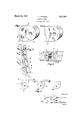
- Fig. 1 is a perspective view of the cushion bumper or check forming the subject matter hereof.
- Fig. 2 is a similar viewot such cushion bumper or check under compression.
- Fig. 3 is a detail perspective view of the jamb of an automobile door showing two of the bumper cushions herein described embodied therein.
- Fig. 4 is a sectional planview'of alrautomobile door and its'jambshowing the relatioirof the'euslr ion bu-mpensuch section being taken on line 44 of Figtii.
- 1 indicates the jumb-of an automobile bodydoor'opening which is usually formed with a 'rabbetQ.
- two cushion bumpers comprising bodies of rubber or other resilient material 3, the inner 'ends of whichare preferably, though not necessarily of substantially semi-circular form abutting upon the inner surface of the socket or mortise of the iamb within which the bumper is seated.
- The' bumper is confined within such soclretor mortise throughout its greater "extent with itscontact face-4 projecting relatively 'a considerable distance within the 'rabbetof the door jamb;
- the contact face 4 of the bumper which .is oneof the marginal end surfaces is preferably, though not necessarily, of convex arcuate form.
- the cushion bumper embodies the characteristics of a solid rubber-bumper as ordinarily employed and is yet capable of the ordinary degree of compression of such bumper.
- rangement of the body gives it an extended range of expansion and contraction in which the contact surface of the bumper is enabled to follow the movement of the door through a greater degree of movement and hence exert its expansive pressure thereon to more effectively prevent rattling or vibration.
- Fig. '5 This range of compressive action is comparatively illustrated'in Fig. '5 wherein a group of cushion bumpers is shown in progressive stages of compression.
- the initial bumper I' is shown fullv expanded.
- the second bumper bodyof the group II is shown subjected to the initial compression during whichthe arched portion 6 has been distorted or flattened to eliminate the opening 5, the displacement of'thecontact face 5 beingindicated by the spacing of the lines AB.
- the position II shows in comparison with'the bumper I the range of additional expansion and contraction afforded by the present construction over thatof the ordinary solid rubber bumper which will quite agree with the bumper-body shown in its compressed form II in Fig.5.
- the present bumper is still capable of further compression through the normal range of an ordinary solid rubber bumper until it ass mes the final compressed form shownat III. Fig. 5.
- the variationor further degree of compression is illustrated by the relative position of the line BC which spacing also indicates the ordinary degree of displacement of the usual solid rubber bumper.
- the bumper body is provided with a countersunk hole-9 to receive an attachment screw for fixedly securing the bumper in its position within the receiving mortise or sockct o the door jamb.v
- Thepresent bumper construction possesses a greatenefiective range ofcompression by whic'hit is enabled toacquire under compression sufficient tension or yielding resistance to prevent a door from rattl ng, even though the bumper. may not necessarily be compressed to its extreme limit: That islto say the present bumper will compensate for lost mot on and inaccuracy .offittingot the door over a much greater range than the'usual bumper.
- V hile the-bumperis capable of a more extended degree'of distortion it isetfective in allits intermediate stages of compreswas claim: V I j l.
- said arched portion affording the contact portion andreceiving the initial pres sure whereby said arched portion is collapsed into contact with the main'portion, the fur- M socket'in a.
- I cushion bumper comprising a resilient f mainjportion to beseated within a receiving door j'amb and a resillentsuppleyielding resistance" to pressure wherein the supplemental portion is subjected to contact pressure tending to initially distort the arouate portion into contact with the main portion,:the subsequent pressure being yieldingly resisted conjointly by the main :and'supple- 3.
- a cushion bumper adapted toaitordprogressively increasing, yielding resistance to pressure including a substantially flat body of resilient'material subjected to longitudinal thrust compression in" itsgeneral plane,
- said body having a hole therein in proximity to the terminal impact surface of the body, I the'material intermediate said'hole and the impact surface being adaptedto yield under compression until said hole is substantially,
- a resilient butter block fixedlyheld in said 2 socket and having anintegral arcuateterminal portion projecting beyond the socket for engagement with a door, said arcuateterminal portion being partially separated from the main body of'the buii'er block by an intermediate space'which' afiords clearance for the initial displacement of the arcuate terminal portion 1nto contact with the main body after which the entire body is subject to compres sion.
Landscapes
- Vibration Dampers (AREA)
Description
March 29, 1932. j B UM N 1,851,344
CLOSURE CHECK Filed May 28, 1928 Patented Mara 1932;
511mm 1 sraTEseaten Ti orries JOSEPHJJBLUMAN, or cnIoAed nLmoIs CLOSURE CHECK Application filed May28, 1928; Serial Ho. 281,041:
' My invention relates to closure checks, and more particularly to a cushion bumper having a maximum effectiverange of displacement whereinythe initial yielding resistance will be materially augmented as the compression progresses. a w
- a While the present form of cushionbumper has been especially designed for arresting the closing movement of automobile doors and the like, it may also be applied to a wide range of other usesas for arresting doors of other structures, islidingudrawers, or-as stops for other moving bodies. Therefore, while the invention will be described in its relatlon to automobile doors it is to be understood that it is notlimited to SHChzfiSG.
In the present invention there is contemplated a body of rubber or a rubber substic tute, having-a resilientcharacteristic to be mounted in a socket'or otherwise suitably supported5-with one end of such body prop jectinga relatively greater distance beyond the mounting thansuch bumpers or checks I ordinarily protrude; This projecting face of the bumper'or check is preferably of convex arcuate form; The resilient body is provided with a hole therein,- preferably of segmental shape, the arcuate sideiofwhich is disposed in substantially concentric spaced relation 5 withtheconvex contact face of the bumper body; Such holeallows sufiicient space for the distortion of the projecting portion of the bumper, which portion yields with minimum resistance until such hole is completely closed whereupon further compresslon 1s resisted conjoint-1y by'suchinitially compressed portion, and the main body of the bumper: In its preferred form this initially compressed projecting contact portion of the bumper body is of substantially arch shape, i theends of which are integrally united with a the main body. V
The primary function of such check or bumper is not onlyftocushion the impingement of the door when closing,{but also to exert a constant outward pressure against this door whenclosed to automat callytake 1 up play between the door latch and keeper plate to prevent rattling or clatter. I i
Rubber door bumpers are now commonly is permitted to rattle or vibrate causing great greater rangeof expansion and compression 7 muchgreater efiective displacement or distortion without necessitating additional door pressure or affording-great resistance. [It protrudes a much greaterdistance beyond its supportand hence it is enabled to follow the door through'a greater range and control its vibratory movementthrough a greater-ex,- V
tent. The cutout or hole, which is preferably though not necessarily of segmental form-,7 afi'ords space into which the excess material 1 maybe compressed and permits the setting up of a bending stress in such protruding portion rather than a direct compressive strain. hen the protruding portion of the cushion 1 bumper. has been initially'compressed sufiiciently to eliminate the curved opening it will thenb-e substantially equivalent to the ordina'ryfsolid bumper and capable ofsti'll furs 3580 ther compression against the resistance of 'the'entire body throughout as great range as the ordinary bumper possesses. r I
The object of the invention is'to simplify I the structure, aswell as the means and mode V of operation Y of cushion bumpers, whereby they will not only be cheapened in construcs tion; but will be more efficient in use, positive in operation, uniform in action, possess ca 0 and: unlikely to get out'ofrepair. 1 3 I a A further obj ect of the invention is to .proc videa resilient cushion or checlrhaving an increased range of expansion and compression, the initialcompressionof whichwill be against a yielding resistance less than that of thesubsequent and Ffinal compression, and
wherein theii'nitial fi'ct will be a' bending I strain followed by bodilycompression at'; i
fording an'efi'ective resistance through allthe 9 I intermediate stages of a wide range of action.
A further object of the invention is to provide a cushion bumper having therein an opening into which the material may be initially displaced to compensate for the increased range of distention of such bumper.
A further object of the invention is to provide a cushion bumper having an increased degree of resiliency, a greater life and durability.
With the above primary and-'oth'erincidental objects in view, as will more fully appear in the specification, the invention consists of the features of construction, the parts and combinations thereof, and the mode of operation, or their equivalents, as hereinafter describedand setforth in the claims.
Referring to theaccompanying drawings, whereinisshown'the preferred, but obviousiy not necessarily the only formof embodiment of the invention, :Fig. 1 is a perspective view of the cushion bumper or check forming the subject matter hereof. Fig. 2 is a similar viewot such cushion bumper or check under compression. Fig. 3 is a detail perspective view of the jamb of an automobile door showing two of the bumper cushions herein described embodied therein. Fig. 4 is a sectional planview'of alrautomobile door and its'jambshowing the relatioirof the'euslr ion bu-mpensuch section being taken on line 44 of Figtii. Fig. 5'illustratesthree cushion bumpers under different degrees o'f compression' showing the relative degrees-of compressionunder different conditions indicated by spaced linescommon to the several views.
Like parts are indicated by similar characters of reference throughout the several views.
In the accompanying drawings, 1 indicates the jumb-of an automobile bodydoor'opening which is usually formed with a 'rabbetQ. Inset in mortises 'or'sockets formed in jamb'l are two cushion bumpers comprising bodies of rubber or other resilient material 3, the inner 'ends of whichare preferably, though not necessarily of substantially semi-circular form abutting upon the inner surface of the socket or mortise of the iamb within which the bumper is seated. 'The' bumper is confined within such soclretor mortise throughout its greater "extent with itscontact face-4 projecting relatively 'a considerable distance within the 'rabbetof the door jamb; The contact face 4 of the bumper which .is oneof the marginal end surfaces is preferably, though not necessarily, of convex arcuate form. Located within the body 3 of the bumper in spaced relation with the convex contact face 4 and preferably concentric therewith is a segmental opening 5. There is thus formed at the outer or effective end of "the bumper body a substantially arch shaped portion 6.the ends of which archa're 55 integrally united with the main body of the bumper While the medial portion thereof is separated from such main body by the strain of the arch section 6 of the bumper body straightening or flattening this arched portion until the opening 5 is completely eliminated as indicated at 8 in Fig. 2. Thereupon the cushion bumper embodies the characteristics of a solid rubber-bumper as ordinarily employed and is yet capable of the ordinary degree of compression of such bumper. As the door is pressed to its final home position, such movement is effected against the conjoint resistance of the initially compressed arched portion 6 and the main portionor body 3. rangement of the body gives it an extended range of expansion and contraction in which the contact surface of the bumper is enabled to follow the movement of the door through a greater degree of movement and hence exert its expansive pressure thereon to more effectively prevent rattling or vibration.
This range of compressive action is comparatively illustrated'in Fig. '5 wherein a group of cushion bumpers is shown in progressive stages of compression. The initial bumper I'is shown fullv expanded. The second bumper bodyof the group II is shown subiected to the initial compression during whichthe arched portion 6 has been distorted or flattened to eliminate the opening 5, the displacement of'thecontact face 5 beingindicated by the spacing of the lines AB. In other Words the position II shows in comparison with'the bumper I the range of additional expansion and contraction afforded by the present construction over thatof the ordinary solid rubber bumper which will quite agree with the bumper-body shown in its compressed form II in Fig.5. However, in this condition the present bumper is still capable of further compression through the normal range of an ordinary solid rubber bumper until it ass mes the final compressed form shownat III. Fig. 5. The variationor further degree of compression is illustrated by the relative position of the line BC which spacing also indicates the ordinary degree of displacement of the usual solid rubber bumper., The bumper body is provided with a countersunk hole-9 to receive an attachment screw for fixedly securing the bumper in its position within the receiving mortise or sockct o the door jamb.v
While the invention has been described in its relation to adoor jamb it is to be under- Thus the shape and arstoodthat it is not limitedto such application, but may be utilized as a stop member torjmoving bodies of other character. Thepresent bumper construction possesses a greatenefiective range ofcompression by whic'hit is enabled toacquire under compression sufficient tension or yielding resistance to prevent a door from rattl ng, even though the bumper. may not necessarily be compressed to its extreme limit: That islto say the present bumper will compensate for lost mot on and inaccuracy .offittingot the door over a much greater range than the'usual bumper.
' The provision of the arched outer portionat torded by the clearance opening causes a bending stress to be set up under which the arch is'fiattened in'addition to a compression strain", by the closin of thedoor upon the bumper. W
V hile the-bumperis capable of a more extended degree'of distortion it isetfective in allits intermediate stages of compreswas claim: V I j l. A CLlSlllOIl bumper includinga' substalb sion,-and.hence its/range of effective operation is, materially lncreased."
Fromtheabove description it willbe ap- ,parentthat there is'thusi provided a con struction of the character described, possessing the particular features of advantage .btjr. fore enumerated as desirable, but WlllCllObVlously is susceptible of modification in its form, proportions and arrangementof parts "without ."departing from the principle 1nvolved or sacrificing any of its advantages.
, While in order to comply with the statute vthe inventionis described in language more or less specific asto structural features, it is I to be understood that the invention is not limited to the specific details shown, but that the means and construction herein disclosed comprise the preferredform of severalmodes of putting the invention into efliect, and. the invention is therefore claimed in any of its forms orxmodifications within-the legitimate and validscope of'the appended claims.
Having thus described my invention, I
tially flat main body of resilient material to be seated within arecess ina door jamb and withthe intermediate portion thereof spaced I an integral arch] shaped extension thereof normally projecting beyond the jamb, the
ends of which are connected to the main body therefrom, said arched portion affording the contact portion andreceiving the initial pres sure whereby said arched portion is collapsed into contact with the main'portion, the fur- M socket'in a.
V as
ther pressure'being resisted conjointly by said parts. i
mental portion {n ormally projecting beyond thev limit oi thereceivingsocket, the crown of which is spaced fromithe main portion, said bumper: aitording progressively increasing mental portions.
, I cushion bumper comprising a resilient f mainjportion to beseated within a receiving door j'amb and a resillentsuppleyielding resistance" to pressure wherein the supplemental portion is subjected to contact pressure tending to initially distort the arouate portion into contact with the main portion,:the subsequent pressure being yieldingly resisted conjointly by the main :and'supple- 3. A cushion bumper adapted toaitordprogressively increasing, yielding resistance to pressure including a substantially flat body of resilient'material subjected to longitudinal thrust compression in" itsgeneral plane,
said bodyhaving a hole therein in proximity to the terminal impact surface of the body, I the'material intermediate said'hole and the impact surface being adaptedto yield under compression until said hole is substantially,
closed bythe distortion of the body and such intermediate portionin contact with the main body beyond the hole, the further compression being yieldingly resistedby the said intermediate portion in main body.- I V 41. In aconstruction 0t thecharacter' described, a block of resilient material, a supporting structure having a socket thereinjin which the block of resilient material is conconjunction with. the
fined. with one marginal 'face projecting be- I yond the support, such projecting portion beof convex shape, the body having a hole 1n that portion confined within the socket affording room for the displacement under compression of the greater portion of the body' 7 projecting beyond the support.
a resilient butter block fixedlyheld in said 2 socket and having anintegral arcuateterminal portion projecting beyond the socket for engagement with a door, said arcuateterminal portion being partially separated from the main body of'the buii'er block by an intermediate space'which' afiords clearance for the initial displacement of the arcuate terminal portion 1nto contact with the main body after which the entire body is subject to compres sion.
. In'testimony whereof, I have'hereunto set my hand this 22nd day of May A. 13.1928.
I i f l JOSEPH J. BAUMAN.
Priority Applications (1)
| Application Number | Priority Date | Filing Date | Title |
|---|---|---|---|
| US281041A US1851344A (en) | 1928-05-28 | 1928-05-28 | Closure check |
Applications Claiming Priority (1)
| Application Number | Priority Date | Filing Date | Title |
|---|---|---|---|
| US281041A US1851344A (en) | 1928-05-28 | 1928-05-28 | Closure check |
Publications (1)
| Publication Number | Publication Date |
|---|---|
| US1851344A true US1851344A (en) | 1932-03-29 |
Family
ID=23075704
Family Applications (1)
| Application Number | Title | Priority Date | Filing Date |
|---|---|---|---|
| US281041A Expired - Lifetime US1851344A (en) | 1928-05-28 | 1928-05-28 | Closure check |
Country Status (1)
| Country | Link |
|---|---|
| US (1) | US1851344A (en) |
Cited By (1)
| Publication number | Priority date | Publication date | Assignee | Title |
|---|---|---|---|---|
| USD320339S (en) | 1989-03-16 | 1991-10-01 | D & P Visions, Inc. | Lock box bumper |
-
1928
- 1928-05-28 US US281041A patent/US1851344A/en not_active Expired - Lifetime
Cited By (1)
| Publication number | Priority date | Publication date | Assignee | Title |
|---|---|---|---|---|
| USD320339S (en) | 1989-03-16 | 1991-10-01 | D & P Visions, Inc. | Lock box bumper |
Similar Documents
| Publication | Publication Date | Title |
|---|---|---|
| US2290331A (en) | Door check for automobiles | |
| US2032600A (en) | Vehicle door check | |
| GB2192423A (en) | Keeper for a motor vehicle door lock and its production | |
| US2693616A (en) | Door checking and holding device | |
| US6367123B1 (en) | Vehicle lid hinge | |
| US1837517A (en) | Check strap assembly | |
| US1851344A (en) | Closure check | |
| US1908839A (en) | Door bumper | |
| DE19645506A1 (en) | Motor vehicle | |
| US1329313A (en) | Buffer for doors | |
| US3195173A (en) | Door hinge, check and hold-open assembly | |
| US3042959A (en) | Door stop | |
| US2149074A (en) | Door check | |
| US2232498A (en) | Door check structure | |
| US1735024A (en) | Doorcheck | |
| US1850229A (en) | Doorcheck | |
| US2427511A (en) | Door latch | |
| US2034905A (en) | Door check | |
| US1668137A (en) | Hinge | |
| US1340866A (en) | Hinge | |
| US1682993A (en) | Hinge | |
| US1755288A (en) | Doorcheck | |
| US1817939A (en) | Latch | |
| US1683713A (en) | Doorcheck | |
| US2962750A (en) | Door locating means for vehicles |