US1851320A - Reading board - Google Patents
Reading board Download PDFInfo
- Publication number
- US1851320A US1851320A US352994A US35299429A US1851320A US 1851320 A US1851320 A US 1851320A US 352994 A US352994 A US 352994A US 35299429 A US35299429 A US 35299429A US 1851320 A US1851320 A US 1851320A
- Authority
- US
- United States
- Prior art keywords
- cover
- arm
- box
- reading board
- book
- Prior art date
- Legal status (The legal status is an assumption and is not a legal conclusion. Google has not performed a legal analysis and makes no representation as to the accuracy of the status listed.)
- Expired - Lifetime
Links
- 108091035710 E-box Proteins 0.000 description 1
- 238000010276 construction Methods 0.000 description 1
- 229940079593 drug Drugs 0.000 description 1
- 239000003814 drug Substances 0.000 description 1
- 239000000463 material Substances 0.000 description 1
Images
Classifications
-
- A—HUMAN NECESSITIES
- A47—FURNITURE; DOMESTIC ARTICLES OR APPLIANCES; COFFEE MILLS; SPICE MILLS; SUCTION CLEANERS IN GENERAL
- A47B—TABLES; DESKS; OFFICE FURNITURE; CABINETS; DRAWERS; GENERAL DETAILS OF FURNITURE
- A47B23/00—Bed-tables; Trays; Reading-racks; Book-rests, i.e. items used in combination with something else
- A47B23/06—Bed-tables; Trays; Reading-racks; Book-rests, i.e. items used in combination with something else characterised by association with auxiliary devices, e.g. line indicators, leaf turners, lampholders, book or page holders
-
- A—HUMAN NECESSITIES
- A47—FURNITURE; DOMESTIC ARTICLES OR APPLIANCES; COFFEE MILLS; SPICE MILLS; SUCTION CLEANERS IN GENERAL
- A47C—CHAIRS; SOFAS; BEDS
- A47C7/00—Parts, details, or accessories of chairs or stools
- A47C7/62—Accessories for chairs
Definitions
- i book may be held in any one of a number of 15 positions, accordingto the desire of the user.
- a further object of this invention is to provide a device of the class described in which the supporting member formsthe cover of a box, the said box serving to receive and con- 2- ceal. the supporting arm when the cover is closed, and also serving as a receptacle for the book.
- a further object of this invention is to provide a reading board which is simple in con- 39 struction, attractive in appearance, and well adapted for the purpose described.
- the invention consists of the improved reading board, andall its parts and combinations,
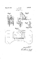
- Fig. l is a perspetciveview ofa chair showing the reading board as used in connection therewith;
- i Fig. 2 is a plan view of the reading board;
- Fig. 8 is a sectional view taken on line 33 of Fig. 2, the full linesshowingithe cover in open position, and the dotted lines showing I the cover in closed position;
- Fig. 4 is an enlarged fragmentary view .53 showing the loop member on the lower side j guide for the supporting arm.
- Fig. 5 is an enlarged fragmentary sec tional view showing I the arm-engaging I bracket.
- Referring to-the drawingdthenumeral 8 designates the base portion which is shown, as substantially rectangular, but which may be of any other suitable shape.
- the inner edge of the" base member is formed with a large recess 9. so as to provide ample room for the reader.
- a box 10 Positioned on a: central portion of the 1 board is a box 10 to one side of which a cover 11 is secured by hinges 12.
- the said cover is provided along its lower edge with a strip of .material 13 forminga supporting shoulder for a book. Near the'other edge ofthe cover, and secured tothe lower side thereof,
- the device In using the device, it is preferably positioned across the arms of a chair, as shown in Fig. 1.
- the cover 11 is then opened to a position similar to that shown by full lines in Fig. 3, the arm 17 sliding over the bracket 22 as the cover is being opened, and automati cally locking it many desired position.
- the box 10 is of sufficient size to accommodate a book, and this convenient feature of construction makes it possible to place the book, which is being read, within the box, so that the reading board and book may be put away together, when not desired, ready to be used again at a latertigpe,
- a supporting board comprising a base member, a bo x port on on the upper surface of slaid base member, a supporting member hingedly connected to a side of said box, an arm'fpiv'otally connectedat one end" to said supporting member near the free edge of the -'latter andhaving'teeth formed on its lower edge near the other end thereof, said arm having a length nearly as great as the width of th'e box and snbstantially having its free end 31) positionable within the box portion greater thank the.
Landscapes
- Purses, Travelling Bags, Baskets, Or Suitcases (AREA)
Description
March 29, 1932.
J. J, NELSON READING BOARD Filed April 6, 1929 X INVENTOR. BY 0? Maw P M I ATTORNEYS.
Patented Mar. 29, 1932 JOHN'J'. NELSON, OF NORTH MILWAUKEE, WISCONSIN READING BOARD Application filed April 6,
i book may be held in any one of a number of 15 positions, accordingto the desire of the user.
A further object of this invention is to provide a device of the class described in which the supporting member formsthe cover of a box, the said box serving to receive and con- 2- ceal. the supporting arm when the cover is closed, and also serving as a receptacle for the book.
It is a further object of this invention to provide a reading board having a novel form of adjustable supportingarm for maintaining the book supporting member in the desired position.
A further object of this invention is to provide a reading board which is simple in con- 39 struction, attractive in appearance, and well adapted for the purpose described.
With the above and other objects in view, the invention consists of the improved reading board, andall its parts and combinations,
as set forth in the claim and all equivalents thereof. 7
In the accompanying, drawings, inwhich the same reference characters designate the same parts in all of the views :1 Fig. l is a perspetciveview ofa chair showing the reading board as used in connection therewith; i Fig. 2 is a plan view of the reading board; Fig. 8 is a sectional view taken on line 33 of Fig. 2, the full linesshowingithe cover in open position, and the dotted lines showing I the cover in closed position; I c
Fig. 4 is an enlarged fragmentary view .53 showing the loop member on the lower side j guide for the supporting arm.
1929. Serial No. 352,994.;
of theoover and the supporting arm extendin therethrough; and i Fig. 5 is an enlarged fragmentary sec tional view showing I the arm-engaging I bracket.
Referring to-the drawingdthenumeral 8 designates the base portion which is shown, as substantially rectangular, but which may be of any other suitable shape. The inner edge of the" base member is formed with a large recess 9. so as to provide ample room for the reader. I i
Positioned on a: central portion of the 1 board is a box 10 to one side of which a cover 11 is secured by hinges 12. The said cover is provided along its lower edge with a strip of .material 13 forminga supporting shoulder for a book. Near the'other edge ofthe cover, and secured tothe lower side thereof,
is a fastening member 14 for engaging a com- '70; I
plementary' fastening member 15 on the box to lockjthe'cover in closedposition. i Secured'to the lower surface of the cover, atoneside thereof, is an angle-bracketlfi, to the end of which, one end of a supporting arm 17 is pivotally connected as at, 18. The I said arm is slightly bent as at v19, and is formed on its outer edge with a plurality of teeth 20. Aloop-shaped member 21, also secured to the lower side of the cover, forms a The teeth on the lower portion of the arm are adapted to engage a bracket 22 secured to and extending from a side of the box.
In using the device, it is preferably positioned across the arms of a chair, as shown in Fig. 1. The cover 11 is then opened to a position similar to that shown by full lines in Fig. 3, the arm 17 sliding over the bracket 22 as the cover is being opened, and automati cally locking it many desired position. It
will be noted that in raising the cover it is,
unnecessary to touch the arm 17, as the latter is etficiently guided by the- brackets 22 and 21, and the'teeth 20 will catch of their own ac-' cord when the hand is removed from the cover. A book may then be placed on the cover as shown'in Fig. 1, the lower edge of the book being supported by the shoulder 13; To close the cover, it is merely necessary to disengage the teeth 20 of the arm 17 from the bracket 22. When in closed position, the arm 17 fits within the box, as is shown by the dotted lines in Fig. 5, and is entirely concealed. The box 10 is of sufficient size to accommodate a book, and this convenient feature of construction makes it possible to place the book, which is being read, within the box, so that the reading board and book may be put away together, when not desired, ready to be used again at a latertigpe,
Although only one form of the invention has been shown and described, it is not desired to be limited to the particular showing, as
1 the broad concept of the invention contemp e esa medication nd qu ents hich may fairly come within the scope of the claim.
What I la m n A supporting board comprising a base member, a bo x port on on the upper surface of slaid base member, a supporting member hingedly connected to a side of said box, an arm'fpiv'otally connectedat one end" to said supporting member near the free edge of the -'latter andhaving'teeth formed on its lower edge near the other end thereof, said arm having a length nearly as great as the width of th'e box and snbstantially having its free end 31) positionable within the box portion greater thank the. depth thereof and adjacent the hin ededge of the supporting member when thifiatteris down, a bracket on an inner side ofr said'lb o x on which the lower edge of said arinj're'sts, said arm being movable with the supporting member when the latter is raised, the "lower edge of the arm sliding over the bracket, and the teeth being engageable with the bracket to hold the supporting member i Jalny adjusted-position, and aloop-shaped member extending from thesupporting memher and surrounding said arm to preventout- Weird. .ii v 'men here f b ymd e m s f the'bozr, i v' testimony whereof I affix my signature.
O N J- ELSO CERTIFICATE OF CORRECTION.
Patent No. 1,851,320. Granted March 29, 1932, to
JOHN J. NELSON.
It is hereby certified that error appears in the printed specification of the I above numbered patent requiring correction as follows: Page 2, lines 29 and 30,
of the eiaim, strike out the words having its free end positionable within the box portion" and insert the same to follow the word "and" in line 31; and that the said Letters Patent should be read with this correction therein that the same may conform to the record of the case in the Patent Office.
Signed and sealed this 3rd day of May, A. D. 1932.
M. J. Moore, (Seal) Acting Commissioner of Patents.
Priority Applications (1)
| Application Number | Priority Date | Filing Date | Title |
|---|---|---|---|
| US352994A US1851320A (en) | 1929-04-06 | 1929-04-06 | Reading board |
Applications Claiming Priority (1)
| Application Number | Priority Date | Filing Date | Title |
|---|---|---|---|
| US352994A US1851320A (en) | 1929-04-06 | 1929-04-06 | Reading board |
Publications (1)
| Publication Number | Publication Date |
|---|---|
| US1851320A true US1851320A (en) | 1932-03-29 |
Family
ID=23387302
Family Applications (1)
| Application Number | Title | Priority Date | Filing Date |
|---|---|---|---|
| US352994A Expired - Lifetime US1851320A (en) | 1929-04-06 | 1929-04-06 | Reading board |
Country Status (1)
| Country | Link |
|---|---|
| US (1) | US1851320A (en) |
-
1929
- 1929-04-06 US US352994A patent/US1851320A/en not_active Expired - Lifetime
Similar Documents
| Publication | Publication Date | Title |
|---|---|---|
| US1666001A (en) | Jewelry case | |
| US1720274A (en) | Covered box | |
| US2573467A (en) | Combined adjustable clothes hanger and pants holder | |
| US1851320A (en) | Reading board | |
| US2278143A (en) | Leaf holder | |
| US1760015A (en) | Vanity case | |
| US1379374A (en) | Folding comfort-chair for children | |
| US2746347A (en) | Slide rule magnifiers | |
| US2226773A (en) | Bookholder | |
| US2486973A (en) | Book match holder | |
| US2067602A (en) | Toilet mirror | |
| US2488605A (en) | Sundial | |
| USD119632S (en) | Hanger supporting head for garment carrying fixtures or the like | |
| USD116940S (en) | Design for a baking iron | |
| US1624467A (en) | Top support for cribs | |
| US1292089A (en) | Desk-table. | |
| USD109840S (en) | Design for a lamp | |
| US2154225A (en) | Watch cover | |
| USD155876S (en) | Design for a combination cigarette holder and ash receptacle or sim- ilar article | |
| USD166668S (en) | h hardy dx | |
| US2463131A (en) | Accounting tray | |
| USD167401S (en) | Christmas lamp ornament | |
| USD159097S (en) | Receptacle for holding coins and the like | |
| USD121510S (en) | Design for a compact | |
| USD168070S (en) | Portable communion set case |